


Abstract
By using quantum nondemolition detectors (QNDs) based on weak cross-Kerr nonlinearities, we propose an experimental scheme for achieving  probabilistic quantum cloning (PQC) of a single-photon state, secretly choosing from a two-state set. In our scheme, after a QND is performed on the to-be-cloned photon and the assistant photon, a single-photon projection measurement is performed by a polarization beam splitter (PBS) and two single-photon trigger detectors (SPTDs). The measurement is to judge whether the PQC should be continued. If the cloning fails, a cutoff is carried out and some operations are omitted. This makes our scheme economical. If the PQC is continued according to the measurement result, two more QNDs and some unitary operations are performed on the to-be-cloned photon and the cloning photon to achieve the PQC in a nearly deterministic way. Our experimental scheme for PQC is feasible for future technology. Furthermore, the quantum logic network of our PQC scheme is presented. In comparison with similar networks, our PQC network is simpler and more economical.
Export citation and abstract BibTeX RIS

Content from this work may be used under the terms of the Creative Commons Attribution 3.0 licence. Any further distribution of this work must maintain attribution to the author(s) and the title of the work, journal citation and DOI.
1. Introduction
The quantum no-cloning theorem, initially recognized by Wootters and Zurek [1] in 1982, is one of the most distinguishing features of quantum systems due to the linearity of quantum mechanics. It guarantees the absolute security of quantum cryptography [2]. The famous theorem has two different kinds of statements: one [1] indicates that the perfect cloning of an arbitrary unknown state in a deterministic way is impossible; the other [3–5] asserts that nonorthogonal states cannot be deterministically cloned with unit fidelity. However, the no-cloning theorem does not preclude the approximate quantum cloning of an arbitrary state or the probabilistic quantum cloning (PQC) of nonorthogonal states. In 1996, Bǔzek and Hillery [6] first designed a universal quantum cloning (UQC) process for optimal cloning of arbitrary two-dimension states. By their UQC process, any two-dimension state can be approximately cloned in a deterministic way. Because of the important applications in quantum information science [7–9], much attention has been paid to UQC, including phase-covariant cloning [10, 11], real-state cloning [11–13], and economical phase-covariant cloning [14–19]. Some kinds of UQCs have also been experimentally achieved based on optical systems [20–23] and nuclear magnetic resonance (NMR) systems [24–26].
PQC of nonorthogonal states was first studied by Duan and Guo [27] in 1998. They showed that states randomly chosen from a known set of states can be probabilistically cloned with unit fidelity iff the states in the set are linearly independent. It has been shown that PQC can improve the performance of some quantum computation tasks [7]. Moreover, PQC has important applications in quantum cryptography. Therefore, since Duan and Guoʼs initial work, PQC has attracted a great deal of attention. Novel PQC machines, which produce linear superposition of multiple copies of the input state [28, 29], and probabilistic cloning with supplementary information [30] have been studied. Analytical solutions have been investigated for the PQC of two qubit states [31], three symmetric qutrit states [32], and equidistant qudit states [33]. In 2011, Chen et al [34] experimentally implemented the PQC of a single-qubit state randomly chosen from two nonorthogonal qubit states set in an NMR system. In 2012, Araneda et al [35] presented a feasible experimental setup for implementing the PQC of two single-photon polarization states based on linear optics together with a pair of entangled twin photons.
Recently quantum nondemolition detectors (QNDs) with the help of weak cross-Kerr nonlinearity have attracted a great deal of attention. They have been investigated for realizing controlled NOT (CNOT) gates [36, 37], generating entangled states [38, 39], implementing entanglement purification and concentration [40–49], etc. In this paper, by using QNDs based on weak cross-Kerr nonlinearity, we put forward an experimental scheme for realizing the economical PQC of two single-photon polarization states. The realization scheme is feasible in the future. We also give the quantum logic network of our PQC scheme. From the network, it can be seen that if the PQC fails, many unnecessary quantum resources can be omitted; and in this sense our scheme is an economical one. Moreover, if the PQC succeeds, our network needs fewer and simpler quantum logic gates than the existing PQC networks in [34, 50, 51].
The rest of this paper is planned as follows. In section 2, we briefly review some previous contributions, including PQC and existing PQC networks. In section 3, we first introduce QNDs based on weak cross-Kerr nonlinearity. Then we propose an experimental scheme for the PQC of two single-photon polarization states by using QNDs. After that, we present the quantum logic network for our PQC scheme. In section 4, we briefly discuss and make comparisons involving our experimental scheme and network. Finally, a summary is given in section 5.
2. Previous contributions
2.1. Duan-Guo PQC machine [27]
The states secretly chosen from the linearly independent set { ,
,  ,⋯,
,⋯,  } can be exactly cloned in a probabilistic way. A Duan-Guo PQC machine consists of a unitary evolution together with a projection measurement. It is written as follows:

where U is the unitary evolution; x, y, and z represent the to-be-cloned system, the cloning system, and the assistant system respectively;  and
and  are normalized states of the assistant system z (not generally orthogonal);
  ,
,  , ⋯,
, ⋯,  are n normalized states of the composite system xyz (not generally orthogonal); and
  (
( ). During the cloning process, after an appropriate unitary evolution U, a projection measurement is performed on the assistant system z. With the probability Υi, one can get the measurement result (MR)
  . Following this projection, the state of the system xy should be
  and the cloning is realized successfully.
The success probabilities of the Duan-Guo PQC machine satisfy theorem 2 in [27]. That is, the matrix  should be positive semidefinite, where
 ![${{X}^{(1)}}=[\langle {{\Psi }_{i}}|{{\Psi }_{j}}\rangle ]$](https://content.cld.iop.org/journals/1367-2630/16/8/083019/revision1/njp498584ieqn15.gif) ,
, ![$X_{z}^{(2)}=[{{\langle {{\Psi }_{i}}|{{\Psi }_{j}}\rangle }^{2}}\langle {{Z}_{i}}|{{Z}_{j}}\rangle ]$](https://content.cld.iop.org/journals/1367-2630/16/8/083019/revision1/njp498584ieqn16.gif) and
and  . From theorem 2, the best success probabilities of PQC can be worked out. Specifically, corresponding to the two-state set (
 ,
,  ), the optimal success probabilities Υ1 and Υ2 satisfy
2.2. Chen et al ʼs PQC machine and network for cloning two qubit states [34]
We now present Chen et alʼs PQC machine and network for cloning two nonorthogonal qubit states. [34] mentions that Chen et alʼs network is simpler than those in [50, 51]. The to-be-cloned state is prepared in

where  and
and  are two orthogonal bases of a single qubit. Chen et alʼs simple PQC machine is expressed as

where  is the unitary evolution of qubits x, y, and z;
  is the optimal success probability of PQC; and
  is the normalized state of qubits x and y. After the unitary operation
  , a projection measurement is performed on the assistant qubit z under bases
  and
and  . From equation (4) one can see that, if the MR is
  with the probability Υ, the original state
  is successfully cloned. On the other hand, with the probability
  one can obtain the MR
  . In this case, qubits x and y collapse to
  and the cloning fails.
The quantum logic network of Chen et alʼs PQC machine is demonstrated in figure 1(a). The network is composed of two controlled-unitary gates (controlled-U1 and controlled-U2), two CNOT gates, a single-qubit Hadmard gate, and a single-qubit projection measurement. Here the unitary operations U1, U2, and H are written as
where  and
and ![$\delta ={\rm arcsin} \left[ \left( \sqrt{\frac{2}{1+{{{\rm tan} }^{4}}\xi }}+\sqrt{\frac{2}{1+{{{\rm tan} }^{-4}}\xi }} \right)/2 \right]$](https://content.cld.iop.org/journals/1367-2630/16/8/083019/revision1/njp498584ieqn34.gif) .
.

Figure 1. (a) Chen et alʼs network for the  PQC of a single-qubit state [34]. Qubits x, y, and z are the to-be-cloned qubit, cloning qubit, and assistant qubit, respectively. ○ and • respectively mean that the control states are
  and
and  . ⊕ indicates the reversal operation controlled by qubit y. U1 and U2 denote the unitary operations controlled by qubit x. H is the Hadmard gate. PM represents the projection measurement. (b) Each controlled-U gate in (a) is composed of two single-qubit unitary operations and a two-qubit controlled NOT (CNOT) gate. See the text for more details.
Download figure:
Standard image High-resolution image3. Experimental scheme for economical PQC of two single-qubit states via QND
In this section, we first introduce weak cross-Kerr nonlinearity and QND. Then we propose our experimental scheme for economical PQC of two single-photon polarization states by using QNDs based on weak cross-Kerr nonlinearity. Finally we present the quantum network for our economical PQC scheme.
3.1. Weak cross-Kerr nonlinearity and QND
The Hamiltonian of cross-Kerr nonlinearity is expressed as [49, 52–54],
where  and a are respectively the creation and annihilation operators, the subscripts P and S denote the probe beam and the signal beam respectively, and κ is the coupling strength of the cross-Kerr nonlinearity. Suppose the input state of the signal mode is the Fock state
  , whereas the probe state is initially in a coherent state
  . The cross-Kerr nonlinearity then causes the combined system of P and S to evolve as follows:
where  , with t being the interaction time. By the way, for the weak cross-Kerr nonlinearity the assumption
  is always satisfied. The coherent beam picks up a phase shift θ directly proportional to the number of the photons in the Fock state
  . Specifically, if n = 0 or 1, the evolution is respectively expressed as

From equation (6) one can see that as soon as the phase shift is measured, we can infer the number of photons in the signal mode.
Now we present the QND based on weak cross-Kerr nonlinearity. See figure 2 for the demonstration. Suppose the probe beam is initially in the coherent state  and the two signal beams are in the following Fock state:

where  . First, the probe beam and the signal beam S1 simultaneously pass through the first cross-Kerr media (CKM), which induces phase shift
  of the probe beam if the signal beam is in the state
  . After that, the probe beam and the signal beam S2 simultaneously interact with the second CKM, which leads to
  for the probe beam if the signal beam S2 has only one photon. After the two interactions, from equation (6) one can see that the entire state of the probe beam and the two signal beams transforms to

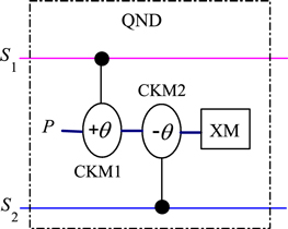
Figure 2. QND based on weak cross-Kerr nonlinearity. S1 and S2 denote two signal modes. P represents the probe mode. CKM1 and CKM2 indicate the cross-Kerr medias, which result in the phase shifts  and
and  of the probe beam (coherent state
  ) only if a photon is presented in signal modes S1 and S2, respectively. XM stands for the X quadrature homodyne measurement. See the text for more details.
Download figure:
Standard image High-resolution imageUsing the homodyne detector, the different coherent states can be distinguished. If the homodyne detector is in the coherent state  , from equation (8) it can be seen that the two signal modes will be projected into the state
  (without normalization). On the other hand, if the result of the homodyne detector is
  (or
(or  ), the collapse state of the two signal modes is
  (or
(or  ). Here we choose the local oscillator phase
  offset from the probe phase. In this case it is called the X quadrature homodyne measurement. With this choice, the states
  and
and  cannot be distinguished [53]. After the X quadrature homodyne measurement, the state of modes S1 and S2 is
where we have defined ![$f(X,Y)\equiv {\rm exp} [-{{\left( X-2Y \right)}^{2}}/4]/{{\left( 2\pi \right)}^{4}}$](https://content.cld.iop.org/journals/1367-2630/16/8/083019/revision1/njp498584ieqn61.gif) and
and  . In equation (9),
  and
and  are two Gaussian curves with the midpoint between the peaks located at
  , and the peaks are separated by a distance
  . If the distance is large enough, the overlap between the two Gaussian curves is small. When
  or
or  , we respectively have the following two outputs:

where ∼ means that there is a low probability of error in distinguishing the two states in equation (10) from each other. By the way, these two states are not normalized. Specifically, if there are no photons in the signal beam S2 [i.e.,  in equation (7)], from equation (6) one can re-express equation (10) as

The QND using weak cross-Kerr nonlinearities has now been introduced. It is the kernel of the following experimental scheme for economical PQC.
3.2. Experimental scheme for economical PQC of two single-qubit states
In this subsection, we introduce a scheme for achieving  PQC based on QNDs combined with linear optics elements. The demonstration of our scheme is shown in figure 3. Photon x is the to-be-cloned photon. The state of x is randomly chosen from the set {
 }, where

 , and
, and  and
and  denote the horizontal and vertical polarization modes of the photon respectively. Note that the value of ξ is given to us, but we do not know whether the to-be-cloned state is
  or
or  . Moreover,
  and
and  are nonorthogonal unless
  is satisfied. This representation is reasonable because any pair of arbitrary qubit states
  and
and  can be transformed into the form of equation (12) by a unitary rotation [34]. To probabilistically clone the state with unit fidelity, an assistant photon z is needed. The initial state of photon z is

where  . First, photon z is split into paths 0 and 1 while x is split into 2 and 3 by using a 50:50 beam splitter (BS) and a polarizing beam splitter (PBS). Note that a reversal operation σx is carried out on the photon in path 1, where
  . This operation is realized by a half-wave plate (HWP) whose axis is set at the angle
  . By the way, the HWP induces the following unitary transformation [55]:

Obviously,  . Then the two photons undergo the following transformation:
where the subscripts 0, 1, 2, and 3 denote the different paths of the photons. After that, photons in paths 1 and 2 are sent to a QND (QND1 in figure 3). It should be mentioned that the photons in paths 1 and 2 correspond to beams S1 and S2 in figure 2. Subsequently, the photon in path 0 is reflected by the one-way mirror (OWM), whereas the photon in path 1 passes through the OWM. The QND has two possible outputs. In subsection 3.1, we demonstrated that the output of a QND corresponds to the X quadrature homodyne measurement result of the probe beam. Corresponding to the MR  or
or  , from equation (10) one can see that photons x and z respectively collapse to the state of

or
The state in equation (16) can evolve to that in equation (15) by modulating an additional phase shift  of the photon in path 2 and a σx operation on photon z. The operations are performed by a classical feed-forward. Incidentally, the feed-forward technique plays an important role in quantum information and computation in that future operations or measurements depend on earlier measurement results. Using current technologies and customized fast electro-optical modulators, we were able to achieve high fidelity (
 ) for detected photons [56]. Before the feed-forward, photons x and z in the state of equations (15) or (16) are delayed in optical single-mode fibers with lengths of 30 m (150 ns). After the classical feed-forward, the state of x and z evolves to equation (15). Then we use a PBS, whose optical axis is placed at the angle
  (PBS
(PBS  in figure 3), and two single-photon trigger detectors (SPTDs) to complete the measurement for photon z with the orthogonal basis
  and
and  , where

With the orthogonal basis  and
and  , equation (15) can be re-expressed as follows:
where Υ is the same as in equation (4). From equation (18), one can see that the upper SPTD in figure 3 captures a photon with the probability  . With this capture, one knows that the MR is
  , and consequently, photon x collapses to the state
  . It is obvious that the cloning process fails and that further operations are unnecessary. So this capture means the cutoff of the scheme. On the other hand, the right SPTD is triggered, which takes place with the probability Υ. It means that the MR is
  . It follows that the collapse state of photon x is

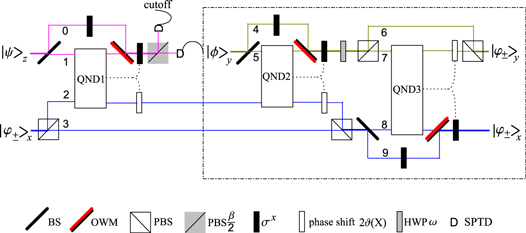
Figure 3.
 PQC of a single-photon polarization state via weak cross-Kerr nonlinearity and linear optics elements. The QND boxes are the same as those in figure 2. The numbers 0, 1, ⋯, 9 depict the paths of the photons. BS denotes the 50:50 beam splitter. OWM indicates the one-way mirror, and it transmits one photon from one side and reflects another photon from another side without remodulating. PBS represents the polarizing beam splitter transmitting horizontal polarization mode and reflecting vertical mode. PBS
  denotes the PBS whose optical axis is placed at angle
  . σx depicts the reversal operation
  . HWP ω represents the half-wave plate whose optical axis is placed at angle ω. SPTD depicts the single-photon trigger detector. And the dot curves stand for classical feed-forwards. See the text for more details.
Download figure:
Standard image High-resolution imageIn the following, we show that the  cloning of the state
  can be deterministically realized from the state
  . In our scheme, the right SPTD is the switch of the components in the dot-line rectangle (see figure 3). Unless the right SPTD is triggered, these components do not work. As soon as it is triggered, a single-photon source emits the cloning photon y and an HWP is used for generating the state

where ![$\delta ={\rm arcsin} [(\sqrt{\frac{2}{1+{{{\rm tan} }^{4}}\xi }}+\sqrt{\frac{2}{1+{{{\rm tan} }^{-4}}\xi }})/2]$](https://content.cld.iop.org/journals/1367-2630/16/8/083019/revision1/njp498584ieqn107.gif) . After a BS in path 5 and an HWP
. After a BS in path 5 and an HWP  in path 4, photons x and y encounter the following evolution:
After that, the QND2, an OWM, and the  operation and phase shift
  corresponding to the outcome of the QND2 are utilized. Here the photons in paths 5 and 2 correspond to beams S1 and S2, respectively, in figure 2. From figure 3, it can be easily seen that these operations are exactly the same as the preceding part. One can use calculations similar to those in equations (14)–(16) to get the following state:

After that, photon y passes through HWPω. Here we set the direction of HWPω with  and
and  . Incidentally, this HWP can realize the unitary transformation of

where  . At the same time, the photon in path 2 is reflected by a PBS, whereas the photon in path 3 transits the PBS. Then, by intensive calculations, one can see that the state in equation (22) transforms to

After that, photon y is split into paths 6 and 7 and x is split into 8 and 9 by using a PBS and a 50:50 BS, respectively. Subsequently, the photon in path 9 passes through an HWP  . Then state of photons x and y transforms to
Photons in paths 7 and 8 are sent to QND3. Incidentally, the photons in paths 8 and 7 correspond to signal beams S1 and S2, respectively, in figure 2. Later photon x passes through the OWM. Corresponding to the two possible outcomes of the QND, photons x and y respectively collapse to

For the collapse of equation (25), the classical feed-forward does nothing. On the other hand, if the collapse state is equation (26), the classical feed-forward performs the additional phase shift  of the photon in path 7 and carries out the
  operation on photon x. Obviously, after the classical feed-forward, the state of photons x and y is that in equation (25). Finally, photon y passes over a PBS. Then equation (25) evolves to

It is obvious that the  PQC has been successfully achieved.
Note that in this scheme we have set  . Of course, ξ can be
  or 0. If
  , the states
  and
and  are orthogonal. Although our scheme works and the success probability is unit in this case, one can first measure the to-be-cloned state by utilizing a PBS and two SPTDs to confirm that state is
  or
or  . Then photon y can be directly prepared in the state
  or
or  according to the MR. By this means, the cloning process is obviously simpler than our previous cloning scheme. On the other hand, if
  , we know that
  , That is, there will be no photons in path 2. The evolutions caused by QND1 and QND2 in this case are presented in equation (11). It follows that, in accordance with calculations similar to those in equations(12)–(27), our scheme apparently works and the success probability Υ reaches
  . From equations (4) and (18), it can be seen that
  . If
. If  , one can obtain
  . Therefore,
  is the lower limit of our PQC scheme. It should be pointed out that for PQC of a state, randomly choosing from a two-state set {
 ,
,  } (here ξ is arbitrary), one can casually prepare
  (or
(or  ). In this way, the probability for getting the correct cloning is just
  . Therefore, the lower limit
  is a useless probability for PQC, and consequently, our scheme is nonsensical in the case
  . The reason is that if
  , the two states are linearly dependent. Theorem 1 in [27] has shown that linearly dependent states cannot be probabilistically cloned. In fact, in the case
  , the to-be-cloned state is unambiguous to us. So there is only one state in the set, and we can directly prepare two photons in
  to complete the cloning. In short, our PQC scheme should not contain the case
  .
.
3.3. Network for our economical  PQC of two nonorthogonal qubit states

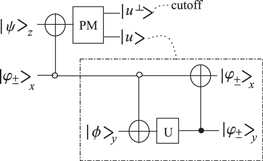
Now we present the quantum network for our economical  PQC in subsection 3.2 (see figure 4). In this network, qubit x is the to-be-cloned qubit and the state is randomly chosen from the set
  (see equation (3)). Qubit z is the assistant qubit that indicates whether the cloning progress is successful. The initial state of qubit z is set as
  . To clone the initial state
  economically, a CNOT gate is first performed on qubits x and z. Here the CNOT gate is represented as

Therefore, qubits x and z undergo the following transformation:
where  and
and  . Incidentally, it can be easily verified that
  . After the CNOT gate, a projection measurement is performed on qubit z with the measurement bases
  and
and  . From equation (29) one can see that, if the MR is
  , qubit x collapses to
  . Obviously, this state does not contain any information about the original to-be-cloned qubit. In this case, the cloning process is discontinued. Otherwise, with the probability Υ, the MR is
  and qubit x collapses to

Note that the probability Υ is just the upper limit of the PQC of two linearly independent states. In this case, one can introduce cloning qubit y and achieve the cloning process deterministically by two CNOT gates and a single-qubit unitary operation. The original state of cloning qubit y is chosen as

The second CNOT gate in figure 4 is simply C in equation (28). The single-qubit unitary operation and the third CNOT gate are respectively represented as
and

After these operations, one can easily obtain the following transformation:

This transformation shows that the state of qubit x is cloned to qubit y. The quantum network for  PQC has now been presented in detail.
Figure 4. Quantum network for  PQC of a single-qubit state. Qubit z is the assistant qubit. Qubits x and y are the to-be-cloned and cloning qubits, respectively. ○, •, ⊕, and PM are the same as those in figure 1.
  and
and  are two possible measurement outcomes. U denotes the single-qubit unitary operation. See the text for more details.
Download figure:
Standard image High-resolution image
4. Discussion and comparisons
In this section, we discuss and make some comparisons involving cross-Kerr nonlinearities and our experimental scheme and network.
Cross-Kerr nonlinearity has been studied extensively with a view to carrying out a number of quantum information processes [36, 37, 40–49, 57]. It should be mentioned that clean cross-Kerr nonlinearity is a rather controversial assumption given current technology. Relative to the atom-cavity system [58] and the Rydberg atomic ensemble [59], natural cross-Kerr nonlinearities are extremely weak [60]. Therefore, the phase shift induced by cross-Kerr nonlinearities is rather small. In 2006, Shapiro [61] pointed out that single-photon Kerr nonlinearities do not help quantum computation. However, given an idealized single-mode coherent state  and a single-photon Fock state
  , one can perform the transformation
  (here θ is a rather small angle) by utilizing weak cross-Kerr nonlinearity [36, 53]. In 2011, He et al [62] investigated the cross-Kerr nonlinearity between the coherent state and single photons. The work of He et al is a significant contribution toward making the treatment of coherent state and single-photon progress interactions more realistic. With the help of weak measurement, Feizpour et al [63] showed that the cross-Kerr phase shift can be amplified to an observable value that is much larger than the intrinsic magnitude of single-photon-level nonlinearity. Zhu and Huang studied the linear and nonlinear propagation of probe and signal pulses that are coupled in a double-quantum-well structure with a four-level double-Λ-type configuration. They showed that giant cross-Kerr nonlinearities can be obtained with nearly vanishing optical absorption [64].
Now we discuss our experimental scheme for PQC. (i) Our scheme is economical. From figure 3, one can see that, after the first QND and classical feed-forward, a projection measurement is performed by a PBS and two SPTDs. If the right SPTD captures a photon with the probability Υ, the latter two QNDs and unitary operations are activated to fulfill the entire cloning process. On the other hand, if the upper SPTD is triggered, cloning is suspended. Therefore, many resources and operations can be omitted if cloning fails. In this sense, our scheme is economical. (ii) The single-photon sources needed in our scheme can be realized. In our scheme, single-photon sources are necessary. Single-photon sources have been recently established in many experiments [65–68]. For example, in 1986, a single-photon state was generated via spontaneous parametric down-conversion and photoelectric detection [65]. In 1999, a single photon source based on controlled single molecule fluorescence was established [66]. In 2000, a train of single-photon pulses was generated by a single-photon turnstile device based on the pulsed laser excitation of a single quantum dot [67]. In 2001, a polarization photon was isolated by utilizing the electrostatic interactions between a laser pulse and a single quantum dot [68]. Therefore, the single-photon sources needed in our PQC scheme can be realized with current technology. (iii) The efficiency of the QND used in our scheme is almost unit. In our PQC scheme, the discrimination between the states in equation (10) is implemented by the X quadrature homodyne measurement. It is the kernel of our experimental scheme for PQC. It has been mentioned that there is a low probability of error with respect to distinguishing the states in equation (10) from each other. In [36], Nemoto et al have shown that in the regime of weak cross-Kerr nonlinearities ( ), the probability of this error occurring is less than 10−5 when the distance
  , In our experimental scheme for PQC, three QNDs are necessary. Therefore, the total efficiency of the QND is
  . It is obvious that the efficiency is almost unit.
The following is a comparison of our PQC network with some existing networks. To the best of our knowledge, three quantum logic networks for PQC of the states in equation (3) have been reported on extensively [34, 50, 51]. The success probabilities of these three networks and our network are exactly the same. The networks in [50, 51] require a two-qubit S gate, a two-qubit D gate, and a single-qubit projection measurement. From figures 1 and 3 in [51], it can be seen that the S gate is equal to two single-qubit unitary operations and two controlled-U gates, and the D gate is equal to seven single-qubit unitary operations and three CNOT gates. Therefore, in this network four CNOT gates, two controlled-U gates, nine single-qubit unitary operations, and a single-qubit projection measurement are necessary. The network in [34] was reviewed in subsection 2.1. From figure 1(a), one can see that two CNOT gates, two controlled-U gates, a single-qubit unitary operation, and a single-qubit projection measurement are used. Obviously, the network in [34] is simpler than those in [50, 51], and it is indeed the simplest one by far. In figure 1(b), we have decomposed each controlled-U gate in figure 1(a) into a CNOT gate and two single-qubit unitary operations. The unitary operations U11 and U22 in figure 1(b) are expressed as
Therefore, four CNOT gates, five single-qubit unitary operations, and a single-qubit projection measurement are necessary in this PQC network. In our network, if the PQC is successful, three CNOT gates, a single-qubit unitary operation, and a single-qubit projection measurement are enough (see figure 4). It is obvious that our network uses the smallest number of quantum logic gates and unitary operations. More importantly, if the PQC fails, only a CNOT gate and a projection measurement are consumed (i.e., the other two CNOT gates and the unitary operation can be omitted). This characteristic has not been mentioned before. Therefore, our network is an economical one. Incidentally, using this network, the  PQC can be achieved in other physical systems, such as the cavity QED system and the ion trap system. We will report them elsewhere.
5. Summary
To summarize, in this paper we propose a PQC scheme using QNDs with the help of CKMs and linear optics elements. This scheme is economical and is feasible for use in future technology. The quantum network of our scheme is presented, and it is simpler and more economical than existing networks for PQC of two single-qubit states.
Acknowledgments
We are grateful to the anonymous reviewers for their helpful suggestions. We acknowledge Professor Ming Yang for holding useful discussions. This work is supported by the 211 Project of Anhui University.