


Abstract
We design a structure to realize Rabi splitting and Rabi oscillation in acoustics. We develop rigorous analytical models to analyze the splitting effect from the aspect of phase matching, and from the aspect of mode coupling using a coupled mode model. In this model, we discover that the splitting effect is caused by the coupling of the Fabry–Perot fundamental mode with the resonant mode of an artificial acoustic 'atom'. We then extract the coupling strength and analyze the impact of structural parameters on it. In addition, we demonstrate Rabi oscillation in the time domain. Such quantum phenomena in the classical regime may have potential applications in the design of novel ultrasonic devices.
Export citation and abstract BibTeX RIS

Content from this work may be used under the terms of the Creative Commons Attribution 3.0 licence. Any further distribution of this work must maintain attribution to the author(s) and the title of the work, journal citation and DOI.
1. Introduction
As an important physical effect, Rabi splitting [1–10] helps researchers understand the interaction between light and matter. In the regime of cavity quantum electrodynamics when a two-level atom is inserted into a high-Q cavity, if the coupling between the atom and the cavity mode is stronger than the decay rate of the atom and cavity, the irreversible spontaneous emission of the atom will be characterized by the periodic energy exchange between the atom and the cavity mode. This effect is called Rabi oscillation. In spectroscopic measurement, this energy exchange is manifested as the anti-crossing dispersion between the atom and the cavity mode, which is called Rabi splitting [4, 5]. Recently, Rabi splitting has been mimicked and demonstrated beyond the atomic scale in various artificial structures including a Cooper pair box coupled to a superconducting transmission line microwave resonator [6, 7] and a semiconductor self-assembled quantum dot coupled to a nanoscale optical cavity mode [5, 8–10].
There have been several attempts in studying Rabi splitting and Rabi oscillation in classical wave regimes, such as electromagnetic waves [11–14], where functional artificial 'atoms' are designed to mimic the two-level atoms. One of the examples of these functional artificial 'atoms' is a split-ring resonator [15], a type of metamaterial with negative permeability at resonance frequencies. When these functional artificial 'atoms' are introduced into resonance cavities (such as near-zero-index [12, 13], multilayer [11], metal-insulator-metal [14] cavities), Rabi-like splitting and oscillation can be observed, due to the coupling of the resonance mode with the functional artificial 'atom'.
Recently sonic crystals [16–18] and acoustic metamaterials [19–24] have attracted great research interest due to the fact that they can be designed similarly as the split-ring resonator to exhibit exotic properties including negative density [25] or negative modulus [26] or both [27]. Such artificial acoustic structures could offer various functionalities including collimation [28], subwavelength imaging [29, 30] and unidirectional transmission [31]. As one of these artificial structures, acoustic cavities, for instance the subwavelength aperture used in the observation of extraordinary acoustic transmission [32–34], has been studied extensively. In this paper, we present an artificial acoustic structure for mimicking the Rabi splitting and oscillation. Such a structure consists of an acoustic 'atom' and a Fabry–Perot (FP) acoustic cavity, where the acoustic 'atom' is a resonance cavity and the FP cavity is a subwavelength aperture. The interaction between the 'atom' and the FP cavity gives rise to acoustic resonance splitting, which is originated from the same mechanism as that in atomic physics responsible for Rabi splitting and oscillation. We show the coupling strength between the acoustic 'atom' and the FP cavity in our system can be manipulated by varying the structural parameters of the acoustic 'atom'. We believe that our results may have some potential applications in the design of ultrasonic devices.
2. Structure and theoretical formalism
The schematic of the artificial structure proposed in this paper to mimic the Rabi splitting and oscillation is illustrated in figure 1. It is composed of two materials, epoxy (Young's modulus: 4.82 GPa, Poisson's ratio: 0.358, density: 1100 kg m−3) and air (density: 1.25 kg m−3, speed of sound: 343 m s−1). This two-dimensional structure (in x-y plane) has a subwavelength slit and a resonance cavity adjacent to the slit. The subwavelength slit itself can be considered as an FP cavity with width a and length b, because its acoustic impedance is mismatched at its two connecting ends. The resonance cavity adjacent to the slit is equivalent to an acoustic 'atom' with width w, depth d, and position measured from the center of the slit Δx.
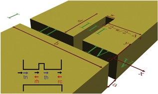
Figure 1. Schematic of the proposed structure, combining a subwavelength slit cavity with an acoustic 'atom' (air-filled rectangular hole). To analyze this complicated structure, it is divided into 5 regions: I, II, III, IV and V. The acoustic wave has a normal incidence onto the structure from region I. The inset illustrates the transmission and reflection coefficients defined in the calculation.
Download figure:
Standard image High-resolution imageIn order to analyze the propagation properties of acoustic waves, this complicated structure is divided into 5 cascaded segments: I, II, III, IV and V as shown in figure 1. The acoustic wave has a normal incidence onto the structure from region I, and its pressure wave could be expressed as  (
( : wave-number in free-space) with a unity amplitude. In region I, the incident acoustic wave experiences interface reflection at the input facet of the FP cavity located at x = −b, so the pressure in this region could be expressed as the sum of the incident wave and the reflected wave [35]
  (
( :
:  component of wave-vector,
  : Dirac delta function,
  : reflection function). In region II, III and IV, since the width of the FP cavity is subwavelength, zeroth order waveguide mode is sufficient to describe the acoustic propagation, the pressure in these regions can be expressed as
  ,
,  , and
, and  (
( ,
,  ,
,  and
and  ,
,  ,
,  are to-be-determined amplitudes for the forward and backward propagating waves). In region V, the acoustic wave only consists of a transmitted forward propagating component from the FP cavity's output facet located at x = 0, and thus its pressure could be expressed as
  (
( : transmission function). Boundary conditions, i.e. continuity of pressure and mass point velocity at the interface, require
  and
and  at the interface between region I and II. Similarly, the same boundary conditions between region IV and V require
  and
and  . At the interfaces formed by region II, III and IV, continuity of pressure and volume velocity require
  and
and  . Assuming a rigid interface at the bottom of the acoustic 'atom', the zero mass point velocity requires
  . By solving the above equations, the pressure in the output region V is obtained as:

where  is the pressure transmission coefficient [36] at the FP cavity's input facet,
  is the pressure reflection coefficient at the FP cavity's output facet,
  and
and  are the pressure transmission and reflection coefficient (illustrated in the inset of figure 1) of the acoustic 'atom', and finally
  .
.
3. Results and discussion
The source normalized transmission spectrum at a position (x, y) = (0.01 m, 0 m) for a structure with subwavelength slit dimension parameters b = 4 mm and a = 0.5 mm is shown in figure 2(a). Both the analytical calculation using the theory developed in the previous section (solid line) and numerical simulation with COMSOL Multiphysics (dashed line) show that the fundamental resonance peak of FP cavity is around 35 kHz. However, with the introduction of an acoustic 'atom' with w = 0.05 mm, d = 2.4 mm, and Δx = 0 mm, the original FP fundamental peak disappears and two new resonance peaks emerge together with a transmission dip in between them. Such change in the transmission spectrum can be explained as follows. The introduction of the acoustic 'atom' breaks the initial phase-coherent conditions inside the FP cavity for multi-reflected waves, and thus the phase-coherent condition has to be restored at some other frequencies. Neglecting the weak higher-order transmitted waves in region V and with the initial input pressure wave  , the pressure of an acoustic wave can be written as the multi-path interference (MPI) of two reflected waves with different paths (shown in figure 2(b)). The first path is formed by the partially reflected wave at site of the acoustic 'atom', and thus the pressure for this reflected wave at the output facet x = 0 becomes
  ; the second path is formed by the partially transmitted wave which will then be reflected at input facet x = −b and interact with the acoustic 'atom' for the second time, and thus the pressure at output facet x = 0 given by this second path becomes
  . Therefore the pressure at the output facet x = 0 will be determined by the coherent summation of the two waves undergoing these two different paths, i.e.
  . Figure 2(c) shows the phase difference between
  and
and  . When the phase difference between
  and
and  is zero corresponding to the two frequencies at ∼30 kHz and ∼40 kHz near the original resonance, these two waves form constructive interference which leads to the appearance of transmission peaks. This kind of distinct resonance splitting behavior obtained here is similar to the Rabi splitting effect in an interaction between an atom and photons.
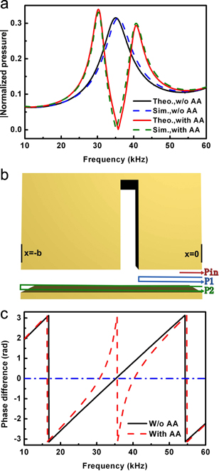
Figure 2. (a) Theoretically calculated and numerically simulated transmission spectra for the slit structure without/with an acoustic 'atom' (AA). (b) Illustration of the propagation path for pin, p1, and p2. (c) Theoretical phase difference (PD) between pin and pref (=p1 + p2) for the case without/with an acoustic 'atom'. PD = 0 means constructive interference, meaning peak transmission. The blue line denotes the zero-PD for reference.
Download figure:
Standard image High-resolution imageUnlike Rabi splitting involving a real atom, in our case the 'atom' is artificial, so we can easily change the characteristics of the resonance frequency of such an acoustic 'atom' and study its influence on the resonance splitting effect. The theoretically calculated transmission spectra (showing as the source normalized transmitted pressure amplitude at point (x, y) = (0.01 m, 0 m) as a function of excitation frequency) under various resonance conditions/frequencies of acoustic 'atoms' (in all the cases FP cavity remains the same, b = 4 mm, a = 0.5 mm) are shown in figure 3(a). Notice that the spectra are shifted with respect to each other by 0.5 along the y-axis for clarity. The resonance frequency of the acoustic 'atom' located in the center of the FP cavity is changed from 50 kHz to 20 kHz by varying its width while keeping the depth/width ratio (40:1) the same. In the following analysis, the left/right resonance peak and transmission dip will be referred as  and
and  . The relationship between
  and
and  is plotted as the black and red dots in figure 3(b), showing an anti-crossing dispersion similar to Rabi splitting.
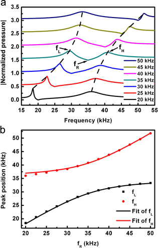
Figure 3. (a) Theoretically calculated transmission spectrum for the slit structure with an acoustic 'atom' of resonance frequencies adjusted from 20 kHz to 50 kHz. The normalized pressure is shifted by 0.5 with respect to each other for clarity. (b) The relationship between fL, fH and fR. The dots are extracted from (a), and the lines are theoretical fits using the coupled-mode model.
Download figure:
Standard image High-resolution imageSuch kind of dispersion relation could be further investigated by studying the mode coupling behavior in our system. Suppose the newly generated modes are resulted from the coupling of the FP fundamental mode with the acoustic 'atom' mode, they must satisfy the eigen equation  . The Halmiltonian matrix is
  and the coupled mode [37] is represented by
  , where
  and
and  stand for FP fundamental mode and the acoustic 'atom' mode,
  and
and  are the corresponding resonance frequency,
  and
and  are the coefficients,
  and
and  are the coupling terms. From the above equations, the resonant frequency of the coupled mode is obtained,
  and
and  , using which the discrete data shown in figure 3(b) are fitted and
  is obtained and shown as 'Fit of
  ' and 'Fit of
  ' in the same figure. It is clear that the fitted curves agree well with those discrete data points calculated with our theoretical model outlined in section 2. Such good agreement also suggests the validity of our assumption that the resulted resonance-splitting is a result of mode-coupling between the FP fundamental mode and the acoustic 'atom'.
In the above coupling model, the coupling strength could be expressed as  , which is dependent upon structural parameters, i.e. the size and position of the acoustic 'atom'. When the width of the acoustic 'atom' is increased, the modal interaction between FP fundamental mode and the acoustic 'atom' mode is enhanced, and the coupling strength thus becomes stronger as shown in figure 4(a). In addition, as the acoustic 'atom' moves away from the center of the FP cavity where the acoustic field of the FP fundamental mode localizes as indicated by the simulation shown in figure 4(c), the coupling strength gets weaker, as illustrated in figure 4(b).
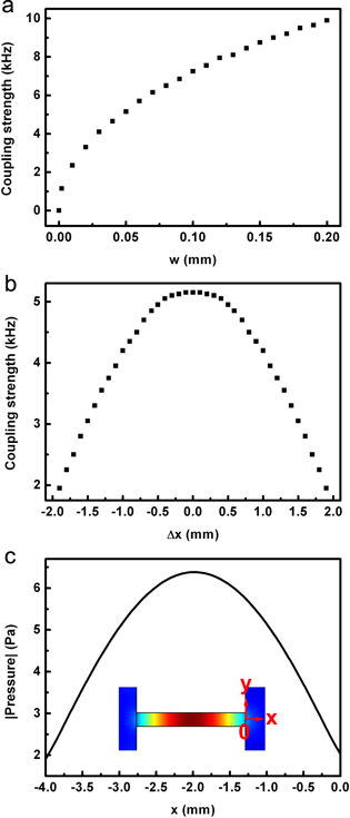
Figure 4. The coupling strength adjusted with (a) the width of the acoustic 'atom' and (b) the 'atom' position in the FP cavity. (c) The simulated field distribution of the fundamental resonance mode of the FP cavity. The pressure amplitude of the incident wave is 1 Pa, and the color from red to blue denotes the amplitude from strong to weak.
Download figure:
Standard image High-resolution imageSince our system closely resembles the atomic Rabi oscillation system, Rabi-type oscillation is also expected in the time domain as a result of the energy exchange between the FP cavity and the acoustic 'atom'. The structural parameters for the system in this study here are b = 4 mm, a = 0.1 mm, w = 1 μm, d = 2.125 mm, and Δx = 0 mm. The incident signal's time-dependent pressure has the form of  , which is plotted in figure 5(a). The real part of the pressure for the output acoustic wave in simulation at the point (x, y) = (0 m, 0 m) as a function of time is shown in figure 5(b). Clearly this pressure oscillates in time domain. This kind of time domain evolution is a direct analogue to atomic Rabi oscillation. The transmission spectrum of the structure is shown in the inset of figure 5(b), with two distinct resonance peaks at 38.5 kHz and 42.2 kHz. Because the acoustic 'atom' and FP cavity have the same resonance frequency, the frequency difference of the two transmission peaks is just 2
 . Therefore, the Rabi oscillation period, determined by 1/(2
 ), should be 1/3.7 kHz = 0.27 ms, which is consistent with the temporal output signal shown in figure 5(b).

Figure 5. (a) The simulated temporal incident signal. (b) The simulated temporal output signal transmitting through the structure with an acoustic 'atom', illustrating an oscillatory behavior. The inset shows the corresponding transmission spectrum, that is pressure amplitude obtained at (x, y) = (0.01 m, 0 m) with incident pressure of 1 Pa.
Download figure:
Standard image High-resolution image
4. Conclusions
In summary, we have designed a structure to realize the Rabi splitting and Rabi oscillation in acoustics. A complete rigorous theoretical model is developed to study the propagation properties of the acoustic wave in this structure. It is shown that the resonance splitting is a result of rebalanced phase-matching conditions after the artificial 'atom' is introduced into the system. In addition, we have also studied the coupling behavior between the FP fundamental mode and the resonance mode of the artificial acoustic 'atom', and shown that the coupling strength is dependent on structural parameters. Moreover, we have investigated the propagation properties of our system in time domain. Rabi-type temporal oscillation phenomenon could also be observed. Our results would be very important for the study of the acoustic analogue of electromagnetic induced transparency if the loss is considered, and would be very useful for the realization of slow sound. We believe that such findings would have great potential applications in subwavelength ultrasonic technologies, such as high quality filter, acoustic signal processing and acoustic sensors [38] for detecting the molecular concentration in fluids.
Acknowledgements
The work was jointly supported by the National Basic Research Program of China (grant no. 2012CB921503 and no. 2013CB632702) and the National Nature Science Foundation of China (grant no. 11134006). We also acknowledge support from the Priority Academic Program Development of Jiangsu Higher Education and FANEDD of China.