


Abstract
High-frequency atomic force microscopy has enabled extraordinary new science through large bandwidth, high-speed measurements of atomic and molecular structures. However, traditional optical detection schemes restrict the dimensions, and therefore the frequency, of the cantilever—ultimately setting a limit to the time resolution of experiments. Here we demonstrate optomechanical detection of low-mass, high-frequency nanomechanical cantilevers (up to 20 MHz) and anticipate their use for single-molecule force measurements. These cantilevers achieve 2 fm  displacement noise floors, and force sensitivity down to 132 aN
  . Furthermore, the ability to resolve both in-plane and out-of-plane motion of our cantilevers makes them excellent candidates for ultrasensitive multidimensional force spectroscopy, and optomechanical interactions, such as tuning of the cantilever frequency in situ, provide opportunities in high-speed, high-resolution experiments.
Export citation and abstract BibTeX RIS

Content from this work may be used under the terms of the Creative Commons Attribution 3.0 licence. Any further distribution of this work must maintain attribution to the author(s) and the title of the work, journal citation and DOI.
1. Introduction
The atomic force microscope (AFM) [1], has become an indispensable tool for probing the physical characteristics of microscopic systems. Working by Hooke's Law,  , the tip of the AFM is displaced proportional to an applied force, transducing forces into a detectable signal. This has been used to great effect for surface imaging, where interatomic forces between an AFM tip and substrate are measured as raster images of the surface structures down to the atomic scale [2] and beyond [3]. The ability to use AFMs in liquid environments [4] has led to their widespread use in biological applications [5], such as live imaging of biological specimens [6], non-scanning applications like studying receptor–ligand binding of surface proteins [7] and deciphering the mechanics of proteins through unfolding experiments [8, 9]. For applications such as these where it is desirable to monitor the dynamics of the system with great time resolution, the bandwidth of the measurement process becomes critical.
High-speed AFM, through the use of MHz frequency resonators [10], has enabled the dynamics of molecular systems to be visualized at speeds of up to 80 ms for a 50 × 100 pixel image [11]. This has permitted the real-time imaging of individual motor proteins [11], proteins diffusing and interacting in lipid bilayers [12], and the folding of synthetic DNA origami structures [13]. When operated dynamically [14], the maximum time resolution of the measurement is limited by the frequencies of the structural modes of the cantilever. In the simple harmonic approximation these are  , where
  and
and  are the effective spring constant and mass of a particular mode [15]. Therefore AFMs with small masses, or large spring constants, grant access to the regime of large bandwidth, exceptional time resolution through increased mechanical frequencies.
The force sensitivity of a mechanical resonator is limited by the thermal forces acting on the resonator. From the fluctuation-dissipation theorem these forces have spectral densities


where  is the Boltzmann constant, T is the bath temperature, and
  is the mechanical quality factor [16]. With this in mind, the thermal noise on a force sensor can be minimized in two general ways: by reducing the spring constants of the devices, or by reducing the effective masses. Single-crystal silicon cantilevers with low spring constants (
 ) have long since demonstrated aN
  force sensitivities at cryogenic temperatures [17]. However, the small
  results in lowered mechanical frequencies, limiting the time resolution of the measurements. On the other hand, reducing the effective masses of resonators typically increases their mechanical frequencies. Further, small dimensions lessen the effect viscous damping has on the reduction of the mechanical Q [18], and thus reduce thermal forces. Therefore minimizing the dimensions, and
  , grants access to the regime of both delicate force sensing, and exceptional time resolution through increased mechanical frequencies.
Today's nanofabrication tools, in particular electron beam lithography (EBL), allow for the design of mechanical resonators with nanometer dimensions and effective masses of picograms or less. Nanomechanical resonators described by Li et al have demonstrated room temperature force sensitivities of 510 aN  in vacuum and 1300 aN
  in air [19]. Using a stressed silicon nitride resonator to provide large mechanical quality factors, Gavartin et al have demonstrated a vacuum room temperature force sensitivity of 74 aN
  [16]. Deserving special mention are force sensors using carbon nanotube resonators, which owing to their tiny effective masses (
 kg) have demonstrated unprecedented force sensitivity approaching the zN
  level at cryogenic temperatures [20].
The force sensing ability of an AFM is dependent on the properties— ,
,  , Q (geometry, material)—of its mechanical resonator. However, to perform measurements with the AFM, a detection method is required to observe the motion of the resonator. While AFMs generally gain better force sensitivity as dimensions are decreased, the task of detecting the displacement of the resonator becomes more challenging. Two common methods traditionally used to detect the displacement of a cantilever are reflecting a laser beam off the cantilever onto a position sensitive photodetector (PD), termed optical beam deflection (OBD), or recombining the reflected beam interferometrically. However, these detection methods scale poorly as the dimensions of the nanomechanical devices fall below the spot size of the laser beam (
 ) [21], creating an effective limit on detectable cantilever sizes (and frequencies) that has already been reached by these detection techniques. However, clever scattering schemes [22], and the resonantly enhanced interferometry of optomechanics have enabled optical detection of sub-wavelength sized resonators.
Cavity optomechanics [23–26] offers excellent displacement sensitivity while being well suited for nanoscale devices. By spatially localizing optical cavity modes with a mechanical resonator, motional degrees of freedom are coupled to frequency (or phase) shifts of the optical modes. These shifts can be carefully monitored, demonstrated by experiments measuring the imprecision in the motion of nanomechanical resonators to the standard quantum limit—the theoretical noise floor of a continuous measurement determined from dynamical backaction and PD shot noise [27].
As broadband noise from the displacement detection system is present in the signal when making a force measurement, an important benchmark of the detection apparatus is the displacement noise floor: the noise corresponding to the minimum displacement resolvable by the detection system. OBD has obtained displacement noise floors of 5 fm  [28], while an all-fibre interferometer has achieved noise floors of 2 fm
  [29], both with standard low-frequency cantilevers (∼300 kHz). By placing a nanomechanical resonator in the evanescent field of an optical microdisk resonator, and detuning the probe laser to the slope of the optical resonance, displacement noise floors of ≈0.2 fm
  have been observed [26, 30].
2. Results and discussion
Here, three sizes of low-mass, MHz frequency, optomechanical devices suited to AFM applications are presented. They consist of cantilever-style nanomechanical resonators coupled to the whispering gallery modes of optical microdisks and are commercially fabricated from a 215 nm thick silicon layer of a silicon-on-insulator wafer, ensuring simple fabrication with automatic and reproducible optomechanical cavity formation. The cantilevers have lengths of 8, 4, and 2  , and are on average 400 nm wide, broadening towards the end to allow binding of molecules to the cantilever, for pulling experiments, without compromising the optical cavity quality (
 for 20
  diameter disk). They couple to disks of 20, 10 and 5
  diameter respectively, and scanning electron microscopy (SEM) images, and finite element method (FEM) simulations of the first three structural modes of the 8
  long cantilever, are shown in figure 1. Devices are measured both in vacuum (
 torr) and air to investigate force sensitivities in different environments. We envision single molecule force (folding/unfolding) experiments as the ideal AFM application for these devices, as this would not degrade the optical Q of the microdisk due to a sample, nor would a separate tip need to be attached.
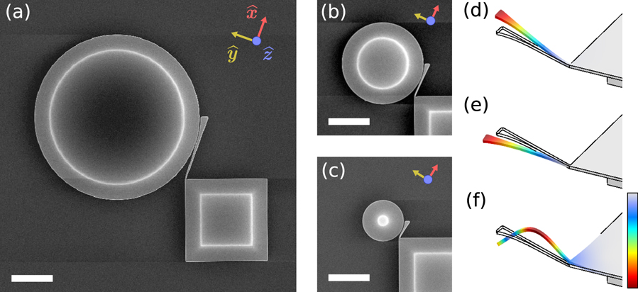
Figure 1. (a) SEM image of the optomechanical device with a 20  diameter optical microdisk evanescently coupled to an 8
  long cantilever. Coordinates are aligned such that
  is parallel to the axis of the cantilever,
  points along in-plane motion of the cantilever, and
  points out-of-plane. (b) 10
  disk, 4
  cantilever and (c) 5
  disk, 2
  cantilever; scale bars 5
  on all panels. (d)–(f) FEM simulations reveal the first three modes of the 8
  long cantilever as an example: an out-of-plane mode, an in-plane mode and a second out-of-plane mode. Mechanical modes of the shorter cantilevers are similar. Colour scale indicates relative displacement.
Download figure:
Standard image High-resolution imageA schematic of the measurement setup is shown in figure 2(a). The motion of a cantilever is measured by coupling light from a tuneable diode laser (New Focus TLB-6330, 1550–1630 nm) to an adjacent microdisk using a dimpled, tapered optical fibre [31] to allow selective coupling to a specific device within a planar array of many devices. The tapering process introduces losses of 50–75% of the original fibre (SMF-28e) transmission, while the dimpling process introduces no appreciable additional losses. The dimple is placed touching the microdisk, opposite to the cantilever (figure 2(b)) to stabilize the fibre against oscillations caused by optical gradient forces. Touching the disk introduces additional scattering losses of  and greatly distorts the optical modes compared to hovering the fibre above the disk, obfuscating optical mode identity. By detuning the laser to the slope of an optical resonance, modulations in the frequency of the optical modes induced by the movement of the mechanical resonator are transduced to a voltage signal from a PD measuring the transmission through the tapered fibre, figure 2(c).
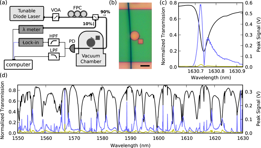
Figure 2. (a) Schematic of experimental setup (VOA—variable optical attenuator, FPC—fibre polarization controller, HPF—high pass filter, LPF—low pass filter, PD—photodetector). (b) Optical image of a dimpled, tapered fibre placed on a 20  diameter disk opposite an 8
  long cantilever; scale bar 20
  . (c) Transmission (normalized to transmission in the absence of coupling) through the tapered fibre (black), while simultaneously locked-on to the out-of-plane mode (light blue) and the in-plane mode (yellow), reveals the maximum peak signal occurs slightly detuned from the optical resonance, approximately corresponding to the maximum slope of the transmission [32]. (d) Scanning the entire frequency range of the tuneable laser reveals optical resonances that provide maximum signal.
Download figure:
Standard image High-resolution imageIn all cases, peaks in the voltage spectral density corresponding to thermodynamic actuation of the fundamental out-of-plane mode were visible, but when measured in vacuum the in-plane modes, and the second out-of-plane mode of the 8  cantilever (figure 1(f)), were additionally visible. Actuation using a broadband longitudinal piezo buzzer revealed that the lowest frequency mode was approximately twice as sensitive to driving voltage, resulting in its identification as the out-of-plane mode. For example, the lower frequency mode of the 8
  cantilever displayed a 50 pm
 amplification of detected signal, while the higher frequency mode displayed only a 20 pm
 amplification. Additionally, mode frequencies were similar to those predicted by FEM simulations. Displacement noise floors of 2 fm
  were observed for the out-of-plane motion of the 4
  cantilever, equivalent to the best noise floors observed using traditional AFM detection methods [28, 29], yet for these radically smaller, lighter, and higher-frequency cantilevers.
The small displacement noise floors achieved with these devices are a direct result of the efficiency in which displacements of the cantilever are transduced into frequency changes in the optical disk. This efficiency can be described to first order by the optomechanical coupling coefficient,  , where
  is the optical cavity frequency. The small gap between the cantilever and the optical microdisk (
 nm) enables good optomechanical coupling. In addition, the cantilevers curve with the microdisk to optimize
  by increasing overlap between the optical whispering gallery modes and the cantilever's motion (table 1). In all devices, the out-of-plane motion of the cantilever had considerably better optomechanical coupling than the in-plane motion, resulting in the difference in displacement noise floors between figures 3(a) and (c), the spectral densities of the 8
  cantilever's two first modes. The apparent symmetry of the out-of-plane motion might suggest a small linear optomechanical coupling for the out-of-plane mode, and while slanted sidewalls of the devices due to fabrication (figure 4(a)) may explain the significant linear coupling observed [32], rough numerical simulations of
  using cylindrically symmetric coordinates (figure 4(b)) estimate that the in-plane coupling should be approximately 10 times stronger. Therefore we suggest the placement of the dimpled fibre touching the top of the optical disk introduces sufficient asymmetries to explain the larger linear optomechanical coupling observed for the out-of-plane modes.
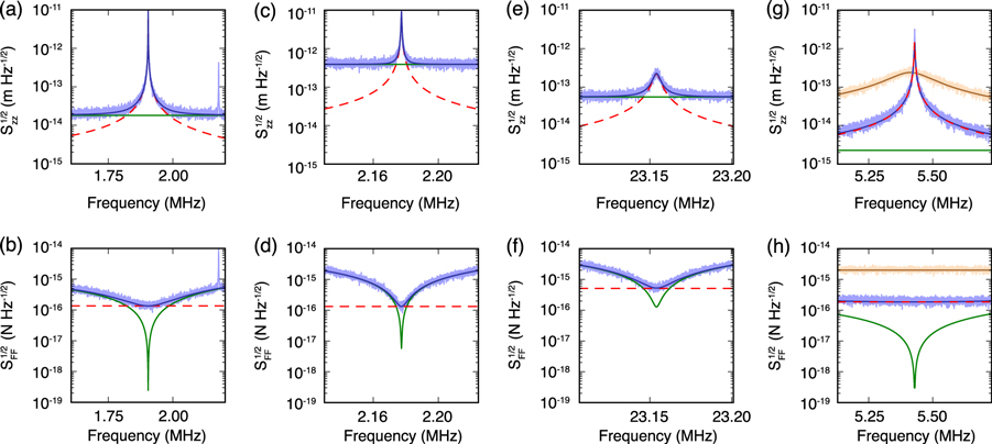
Figure 3. (a) A peak in the displacement noise density,  , corresponding to out-of-plane motion of the 8
  cantilever. The peak at higher frequency is the in-plane mode.
  is fit to a superposition (blue) of the thermal noise of the cantilever (
 , red dashed) and a constant measurement noise, the displacement noise floor (
 , green). (b) By dividing
  by the force susceptibility,
  , the measured force noise density,
  , can be obtained. (c)
  and (d)
  , corresponding to the 8
  cantilever's in-plane mode, and (e), (f) second out-of-plane mode. In all cases
  is limited by thermal forces when at the cantilever resonance frequency and limited by detector noise off-resonance. (g)
  , and (h)
  of the 4
  device's out-of-plane mode are dominated by thermal noise across a wide frequency range due to the low optomechanical detection noise floor. Shown in light brown are
  and
and  in air, with corresponding fits in dark brown.
  in air agrees with that in vacuum, but
  is limited to 2 fN
  due to the viscous damping, compared with 180 aN
  .
.
Download figure:
Standard image High-resolution image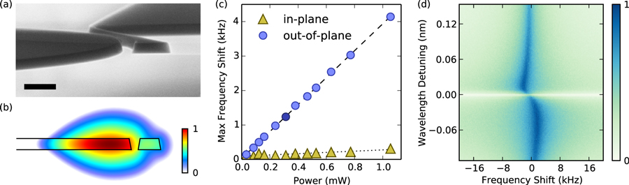
Figure 4. (a) Tilted SEM image of a device with a 4  cantilever; scale bar 500 nm. Side walls have a slope of approximately
  from vertical, creating asymmetries in the optomechanical coupling. (b) FEM simulation of an optical mode in cylindrically symmetric coordinates. Colour bar indicates the relative log magnitude of the electric field. (c) Blue-detuned laser light used to detect the
  device results in stiffening of the cantilever. The frequency of the out-of-plane motion increases by ∼0.1%, while the in-plane motion shows negligible effect due to its
  smaller
  (table 1). Errors in power and frequency shift are similar to the marker size. Maximum positive frequency shift is plotted, as the optomechanically induced frequency shift of the cantilever is dependent on the laser detuning from the optical resonance. The darkened data point corresponds to the data shown in (d). (d) An example measurement of the voltage spectral density measured as the laser is scanned towards larger wavelengths. Darker colours indicate larger spectral density (log scaled).
Download figure:
Standard image High-resolution image
Table 1.
Measured parameters of investigated devices. Data is presented for three optomechanical devices of varying size, but similar geometry (figure 1), with cantilevers approximately 2, 4 and 8  long. For each device at least two different mechanical modes were detected. Effective masses (
 ) for each mode were computed from dimensions measured with SEM, using FEM to determine the mode shape [15]. Peaks were thermomechanically calibrated to extract
  , the cantilever's resonance frequency, Q, the mechanical quality factor in vacuum, and
  , the displacement noise floor. From these parameters we compute
  , the mode's effective spring constant, and
  , the spectral density of thermal forces on the cantilever imposing a force sensing limit. When measured in air, the quality factors of the cantilevers were reduced by viscous damping and only the out-of-plane motion could be detected thermomechanically. Smaller cantilevers exhibited larger quality factors in air, and smaller thermal forces, resulting in better force sensing ability—opposite to the case in vacuum.
| Cantilever Length |

|

|

|
Q (air) |
 (air) (air) |
 (air) (air) |

|
|---|---|---|---|---|---|---|---|
| [μm] | [fg] |
![$[\text{N}{{\text{m}}^{-1}}]$](https://content.cld.iop.org/journals/1367-2630/16/3/035001/revision1/njp482975ieqn102.gif)
|
[MHz] | [fm  ] ] |
[aN  ] ] |
|
|
| 2 out-of-plane | 140 | 2.2 | 20.1 | 3600 (120) | 20 (18) | 290 (1500) | 2000 |
| 2 in-plane | 180 | 3.3 | 21.4 | 5000 | 120 | 280 | 340 |
| 4 out-of-plane | 240 | 0.30 | 5.43 | 4300 (35) | 2 (3) | 180 (2000) | 720 |
| 4 in-plane | 260 | 0.48 | 7.04 | 4400 | 300 | 200 | 6 |
| 8 out-of-plane | 610 | 0.087 | 1.90 | 6500 (22) | 18 (17) | 135 (2300) | 150 |
| 8 in-plane | 610 | 0.11 | 2.18 | 7800 | 390 | 132 | 7 |
| 8 2nd out-of-plane | 610 | 13 | 23.2 | 5600 | 55 | 510 | 57 |
The linear susceptibility,  (A.2), relates displacements of the cantilever's tip,
  , to applied forces,
  . By dividing the measured displacement spectral density by
  , the observed force spectral density can be found (figures 3(b), (d), (f), (h)). The thermal forces on the cantilever impose a minimum force sensitivity, and in all cases in which the thermomechanical motion of the cantilever was detected, the total force noise—a combination of both the thermal forces on the cantilever and noise in displacement detection—reached a minimum at the cantilever resonant frequency equal to the thermal noise,
  . In vacuum, both the in-plane and out-of-plane modes of the 8
  cantilever, exhibited the best observed force sensitivity of ∼130 aN
  , figures 3(b), (d). However in air, the situation was reversed and the 2
  cantilever presented best force sensitivity of 1500 aN
  .
.
While the devices presented here don't set a record for any individual metric, we believe they provide an excellent candidate for carrying out force measurements in certain regimes, namely the sensitive measurement of forces at room temperature and atmospheric pressures. The smallest ( = 50 fg) piezoresistively detected nanomechanical resonator of Li et al [19] achieves a force sensitivity of 1300 aN
  , not much smaller than the 1500 aN
  achieved with our smallest device, but with slightly less displacement resolution (39 fm
  ) than with our optomechanical detection mechanism (18 fm
  ). Alternatively, the in-air optomechanically detected doubly clamped beam geometry of Srinivasan et al [33] and Liu et al [30] achieve 10 times better displacement noise floors, but fall short on force sensitivity (4400 aN
  versus 1500 aN
  ).
).
To the authors' knowledge, the optomechanically detected silicon nitride nanostrings presented by Gavartin et al represent the best micromachined (i.e. not grown like carbon nanotubes [20] or silicon nanowires [34]) room temperature force sensors reported in the literature. Recalling the force sensitivity given by (1), these devices gain their sensing ability from the high intrinsic (i.e. in vacuum) quality factors of high-stress silicon nitride strings [18]. Since additional dissipation mechanisms present in air would likely dominate over the intrinsic vacuum dissipation mechanisms, we imagine that at atmospheric pressure nanostrings would lose their quality factor advantage, and because of the much larger  of the strings (9 pg) versus the devices presented here (0.14 pg), our devices may achieve better force sensitivity. Further, all three of the above compared force sensors were fabricated using EBL. Devices presented in this paper were fabricated at a commercial foundry (IMEC) using deep UV lithography, a process much better suited to the commercial fabrication of many such devices. We imagine EBL could be used to produce optomechanically detected cantilevers similar to those presented here, but with
  similar to those presented by Li et al, providing equivalent force sensitivities, but with possibly better displacement noise floors.
While  was reached regardless of detector noise, low displacement noise floors broadened the frequency range over which thermally limited force noise was observed (e.g. figures 3(b) versus (h)). Therefore small displacement noise floors, while not reducing the minimum force sensitivity, allow for larger bandwidth (faster) force measurements. Larger bandwidth could also be achieved with feedback [16], or as has recently been pointed out in the literature, additional post-processing of the data with an appropriate filter [35], broadening the width of the peaks without affecting
  , and allowing wide bandwidth measurements at the thermal noise level for fast scanning [36].
Operating an AFM at low bath temperatures would reduce thermal noise on the cantilevers, as described by the fluctuation-dissipation theorem. Accordingly, the best force sensitivities have been reached on devices at cryogenic temperatures. Assuming device parameters ( ,
,  ,
,  ) remain constant across temperatures, a thermal force noise of 3 aN
  at 100 mK is expected to be detectable above the room temperature displacement noise floors of the 8
  cantilever's out-of-plane motion. This is comparable with the 0.5 aN
  force sensitivity detectable by a conceptually similar superconducting microwave resonator [37], or the 0.8 aN
  sensitivity of kHz frequency cantilevers used for magnetic resonance force microscopy (MRFM) [17]. Thus we propose optomechanically detected nanomechanical resonators are also good candidates for low-temperature, high-frequency, precision force measurements.
While the optomechanical coupling allows readout of the cantilever's position by monitoring the optical resonator, it also provides radiation pressure back-action on the mechanical device affecting its dynamics. Since in our devices the time scale of optical cavity relaxation is much quicker than the mechanical response time  (i.e. unresolved sideband regime), the radiation pressure forces provide only an optical spring effect, allowing the tuning of
  to within
  (figure 4(c)), as opposed to any optomechanical heating or cooling [38].
3. Conclusion
Optomechanical AFMs provide the path to ultra-sensitive molecular force probe spectroscopy, high-speed AFM, and other AFM applications. By comparing three different sized force sensing devices, we have demonstrated a trade off in force sensing ability between low spring constant and low effective mass devices depending on the application of interest: the larger, low spring constant device provided best force sensing in vacuum, but the smaller devices excelled at ambient pressure. We have demonstrated optomechanical detection of sub-picogram effective mass multidimensional AFM cantilevers that are commercially fabricated, with displacement noise floors down to 2 fm  , and 130 aN
  force sensitivity in vacuum at room temperature. Challenges remain, including selective attachment of relevant molecules, yet we envision that extension of the devices presented here to aqueous environments will open new doors in high-speed, high-resolution molecular force measurements.
Acknowledgments
The authors wish to thank University of Alberta, Faculty of Science; the Canada Foundation for Innovation; the Natural Sciences and Engineering Research Council, Canada; and Alberta Innovates Technology Futures for their generous support of this research. We also thank Greg Popowich for technical support, along with Mark Freeman, Wayne Hiebert and Paul Barclay for helpful discussions.
Appendix A.: Thermomechanical calibration
To calibrate the voltage spectral density,  , measured from a PD into a displacement spectral density,
  , of the movement of the cantilever's tip, the thermal forces on the cantilever can be used. By way of the fluctuation-dissipation theorem, the thermal forces acting on a cantilever's mode are constant across frequencies with a spectral density of [15, 16]

where  is the Boltzmann constant, T is the system temperature,
  is the mode's resonance frequency, Q is the quality factor, and
  is the effective mass of the cantilever (described further below). Using the linear susceptibility of a damped harmonic oscillator,

the theoretical displacement spectral density corresponding to thermomechanical actuation of the cantilever mode is known:  . Further, assuming the voltage measured is linearly proportional to cantilever displacement, and the noise from the measurement apparatus is constant across frequencies of interest, a theoretical fit to the voltage spectrum can be found [15],

where  is the voltage noise floor density and
  is a conversion factor between volts and metres, i.e.
  . Substituting in the thermal displacement noise,

Because it is not possible to differentiate both  and
and  from the fit,
  is calculated beforehand from measured cantilever dimensions. By modelling the structural modes of the cantilever using FEM, the mode shape of interest,
  , which is the mechanical displacement of the mode from its undeformed position,
  , normalized to the maximum displacement, can be determined and the effective mass can be computed by carrying out an effective mass integral over the volume of the cantilever [15, 24],

By fitting the measured  to (A.4), the resonance frequency (
 ), quality factor (Q), noise floor (
 ), and the voltage-displacement conversion factor (
 ) used to calibrate the spectrum, can be determined.
Appendix B.: Determining the optomechanical coupling coefficient
By performing thermomechanical calibration, the voltage-displacement conversion factor,  , was found. Since
  linearly converts displacements of the cantilever (
 ) to volts from the PD (
 ),
),  . Examining the optomechanical detection mechanism, the displacement to voltage transduction can be divided into two steps, displacement to optical cavity frequency (
 ) shifts, and
  to transmission (voltage) transduction. Therefore, with help of the chain rule,
  ). Here
  is the optomechanical coupling coefficient,
  [26]. By calculating the slope of laser transmission versus laser frequency at the frequency of light the mechanical signal was detected at (e.g. from figure 2(c) in the main text),
  can be determined, enabling calculation of
  .
.