


Abstract
The spin texture of a Dirac-type surface state in W(110) lends itself to study spin-dependent effects in electron spectroscopies that show up very clearly. Firstly, we report on spin-resolved photoemission calculations and separate the spin polarization that is attributed to the initial state from that induced by the photoemission process itself. This disentanglement allows one to map spin textures of spin-polarized initial states using circular dichroism, for example from Dirac surface states in topological insulators. Secondly, we demonstrate the mapping of spin-polarized states by spin-dependent two-electron emission. Selecting highly polarized initial states, this spectroscopy can furthermore probe the spin dependence of the exchange-correlation hole.
Export citation and abstract BibTeX RIS

Content from this work may be used under the terms of the Creative Commons Attribution 3.0 licence. Any further distribution of this work must maintain attribution to the author(s) and the title of the work, journal citation and DOI.
1. Introduction
Topological insulators are a fascinating new class of materials [1]. In particular, strong topological insulators show a surface state with unique properties at the center of the surface Brillouin zone [2]: it bridges the fundamental band gap, disperses linearly and exhibits a Rashba-type spin texture [3–5]. These features have led to an extensive ongoing search for new topologically non-trivial materials (e.g. [6–9]). But also well-known materials are being re-investigated with respect to surface states that show some features of a 'true' Dirac surface state. Recently, a Dirac-type surface state (DSS) has been identified at the (110) surface of tungsten [10–12]. Although known for some time [13], its Dirac properties have been proven experimentally by spin- and angle-resolved photoelectron spectroscopy [14] by Miyamoto and co-workers [10]. These findings have been complemented theoretically by first-principles calculations [15, 16].
It is these salient properties of the DSS in W(110) that lend support for investigations of spin-driven effects in electron spectroscopies [17–19]. In this paper we elaborate on how these show up in spin- and angle-resolved photoemission (SARPES) [20, 21] and in electron pair emission (e,2e) [22, 23].
The first spectroscopy covered in this paper is SARPES. The spin of the DSS (i.e. the initial state in SARPES) is completely in-plane. The photoemission process itself lowers the symmetry of the entire setup and, hence, allows for a non-zero perpendicular component of the photoelectron's spin polarization. While this effect has been addressed briefly for linearly polarized light in [16], we focus in this paper on circularly polarized light. Questions to be answered comprise the effect of 'optical orientation' [24] on the photoelectron spin in dependence on the symmetry of the setup. Furthermore, mapping the spin texture of the Dirac state in three-dimensional topological insulators [1, 25–27] by circular dichroism experiments [28, 29] is challenging, due to the specific occupied surface electronic structure of the prototypical systems (i.e. the bichalcogenides Sb2Te3, Bi2Te3, Bi2Se3). In particular, the Dirac surface state is very close (in (E,k)) to bulk states and the energy range accessible by photoemission is rather small (the fundamental gap is less than 0.2 eV wide). This is different for the DSS in W(110) that 'resides' in a wide band gap and shows features strongly reminiscent of those of a true Dirac state. Hence being—roughly speaking—'isolated', this surface state represents a prototypical system for studying the joint effect of 'optical orientation' and spin texture on circular dichroism of Dirac-type states [29, 30]. We provide a method to disentangle the origin of the photoelectron's spin polarization—initial state or optical orientation—by taking appropriate intensity differences which may prove useful also for studying Dirac states of topological insulators.
Complementary to photoemission, we explore the spin-polarized surface states by means of a second spectroscopic method: electron-induced emission of correlated electron pairs, commonly referred to as (e,2e) spectroscopy (see [15] and references therein). The spin orientation of the incident low-energy electrons relative to the surface state electrons, with which they collide, entails either parallel or anti-parallel spins of the two outgoing electrons. The two electrons are therefore correlated either by exchange and Coulomb interaction or by Coulomb interaction only, which implies a fundamental difference between the (e,2e) reaction cross sections (intensities) in the two cases. This spin dependence allows a spin-resolved mapping of the surface state dispersion relations. We demonstrate this by relating spin-dependent (e,2e) spectra to the underlying spectral density in the surface layer resolved with respect to spin and spatial parity. Selecting on such a map a highly spin-polarized initial state and keeping it fixed, momentum distributions of the emitted electrons exhibit a large exchange-correlation hole for parallel spins and a much smaller correlation hole for anti-parallel spins.
The paper is organized as follows. Theoretical aspects are addressed in section 2. Results are discussed in section 3, focusing on SARPES in section 3.2 and on (e,2e) in section 3.3. We conclude with section 4.
2. Theoretical aspects
2.1. Electronic structure calculations
The electronic structure calculations were performed within the framework of the local spin-density approximation to density-functional theory. Our computations rely on the layer Korringa–Kohn–Rostoker (KKR) method for spin-dependent systems [31, 32]. In this relativistic approach, spin–orbit coupling is accounted for by solving the Dirac equation. The site-dependent potentials have been obtained by full-potential augmented plane waves (FLAPW) calculations6 and subsequently transferred to our KKR code. Since all the results presented in this paper rely on the computational setup used earlier, it is sufficient to sketch its main ingredients here; for details see [15].
The W(110) surface is treated as a semi-infinite system, in which the potential in the outermost three layers differs from that of the bulk-like layers (with bulk potential). The top layer is relaxed inward by Δd = −3% with respect to the bulk interlayer distance, in agreement with low-energy electron diffraction (LEED) and surface x-ray diffraction analyses [33, 34]. The image-potential barrier is taken as a smooth interpolating function [35].
From the layer-resolved Green function Gll of the entire system, we calculate the spectral density Nl(E,k) for layer l at energy E and surface-parallel wavevector k

By taking appropriate partial traces, the spectral density can further be decomposed with respect to angular momentum and spin projection. When discussing the spin texture of the Dirac surface state, we rely on spin differences

of spin-dependent spectral densities that are resolved with respect to the chosen spin quantization axis μ.
2.2. Photoemission calculations
SARPES spectra were calculated within the relativistic one-step model of photoemission [31, 36, 37], using our layer KKR computer code. Spin–orbit coupling, boundary conditions and the transition matrix elements between the initial state and the time-reversed spin-polarized LEED state (that describes the outgoing electron) are fully taken into account. The result of the computation is the spin density matrix  of the photoelectron that depends on the kinetic energy E and the detection direction of the photoelectron (expressed in terms of the wavevector k). It gives the intensity
  and the spin polarization
  of the chosen spin quantization axis
  (
(  vector of Pauli matrices).
Excitation of the DSS by linearly polarized light has been investigated earlier [16]. In this paper, we focus on circularly polarized light (helicity σ±) with a photon energy of 21.22 eV (HeI); this particular energy was chosen because it is available both in synchrotron radiation facilities and from rare-gas discharge lamps in a laboratory. We investigate three setups— ,
,  and
and  —with decreasing degree of symmetry. While setup
  is for normal incidence,
  is for off-normal incidence within the
  –
–  –
–  mirror plane of the surface ([001] direction). In both cases we focus on electron detection in the
  –
–  –
–  mirror plane in which the surface state shows almost linear and strong dispersion. Setup
  is for off-normal incidence and electron detection in [
 ] direction (
 –
–  –
–  ) which is not a mirror plane. The surface state shows strong dispersion in this plane as well [10]. It becomes 'flattened' along
  –
–  –
–  [11]. For
  and
and  the polar angle of incidence ϑph is chosen as 45°.
In setups  and
and  , the spin polarization of the Dirac surface state is fully aligned perpendicular to the mirror plane. Considering as an example an xz mirror plane (s in table 1), sy does not change sign upon reflection and, hence, is allowed non-zero, in contrast to sx and sz. The photoemission process lowers this symmetry restriction because the electric field A of the light has to be considered in addition (A in table 1). For circularly polarized light incident within the xz plane, the electric field vector can be expressed as

In particular, Ay changes sign upon reflection mxz: left-handed circular polarized light is turned into right-handed circular polarized light, and vice versa (σ± → σ± in table 1). As a consequence, the total photocurrent I is unchanged with respect to reversal of the light helicity: there is no circular dichroism [38]. Furthermore, all spin components of the photoelectron are allowed non-zero but sx and sz change sign upon helicity reversal while sy does not. In a schematic notation, (I;sx,sy,sz;σ±) = (I; − sx,sy,−sz;σ±) holds.
Table 1. Effect of mirror operation mxz on the photoelectron spin vector s. = (sx,sy,sz), the vector potential A = (Ax,Ay,Az) of the incident light in photoemission, and its helicity σ in the case of circular polarization. The wavevector k is along the kx-axis (ky ≡ 0).
| Identity | 1 | sx | sy | sz | Ax | Ay | Az | σ± |
|---|---|---|---|---|---|---|---|---|
| Reflection at xz plane | mxz | −sx | sy | −sz | Ax | −Ay | Az | σ± |
In setup  , both light incidence and electron detection are not within a mirror plane of the surface, leading in general to circular dichroism; furthermore, all Cartesian components of the photoelectron's spin polarization s may be non-zero.
2.3. (e,2e) calculations
We employed a relativistic KKR-type formalism, which has been presented in detail in earlier work [22, 39]. The basic ingredients are four one-electron states |i〉 (with i = 1,2,3,4), which are obtained as solutions of the Dirac equation with a complex potential and are characterized by energies Ei, surface-parallel momenta ki and Rashba component spin labels σi = ± . In the (e,2e) process, the Coulomb interaction induces a transition from an initial two-electron state |1,2〉, which is an antisymmetrized product of the primary electron state |1〉 and the valence electron state |2〉, to a final two-electron state representing the two emitted electrons. |3,4〉 is an approximate solution of a two-particle Dirac equation with the electron–electron interaction approximated by a screened Coulomb interaction. Being of course also antisymmetric with respect to interchanging the two electrons, it involves essentially products of the two one-electron states |3〉 and |4〉 and a Coulomb correlation factor. For details we refer to [39]. An important property of the (e,2e) process is the conservation of energy and parallel momentum:

where g is a surface reciprocal lattice vector.
The spin-resolved (e,2e) reaction cross sections 'intensities' can be expressed in a golden rule form with Coulomb matrix elements between the above initial and final two-electron states. Denoted by Iσ1σ3σ4, they involve a sum over the valence electron spin labels σ2 and depend explicitly on the spin labels of the incoming and the two outgoing electrons. For parallel spins (σ3 = σ4), the Iσ1σ3σ4 contain both exchange and Coulomb interaction between the two emitted electrons, whereas for antiparallel spins, they contain only the Coulomb interaction. Further, they are in general functions of Ei and ki, with i = 1,3,4. For fixed Ei and ki, 4 implies definite valence electron energy and parallel momentum, i.e. one can map the dispersion relation of the valence electron states.
3. Results and discussion
3.1. Dirac-type surface state
As a prerequisite for discussing the electron spectroscopies, we recall briefly the salient properties of the DSS. We focus on the directions in which this state disperses strongly [11]. Along  –
–  –
–  (left in figure 1), the dispersion is almost linear, while it becomes slightly parabolic along
  –
–  –
–  (right in figure 1). Its Dirac point shows up at EF–1.25 eV and
  , in agreement with experiment [10, 12]. The orbital decomposition of the top layer's spectral density yields that the surface state belongs to the Σ1 (single-group) representation7, with the by far largest contribution from dz2 orbitals.

Figure 1. Electronic structure of W(110) for wavevector k along  –
–  –
–  ((a)–(c), left) and along
  –
–  –
–  ((d)–(f), right). Normalized spin-integrated spectral densities are shown as color scale for a bulk layer ((a), (d)) and for the topmost surface layer ((b), (e)). The red–white–blue color scale for (c) and (f) displays data for negative-zero-positive normalized spin differences SSμ(E,k), with μ the Rashba component of the spin polarization. The spin polarization of the DSS is as large as 90% (in absolute value) close to the Dirac point. a0 Bohr radii, EF Fermi energy.
Download figure:
Standard image High-resolution imageThe spin texture is of Rashba-type, as dictated by point group and time-reversal symmetry, namely in-plane and perpendicular to k (this spin-polarization component is usually termed 'the Rashba component'). Time-reversal symmetry dictates a spin reversal upon turning k into −k (cf the red–blue asymmetry in panels (c) and (f) of figure 1). The degree of spin polarization is about 90% (in absolute value) close to the Dirac point. It exceeds that of the Dirac surface state in the topological insulator Bi2Te3 (about 60% [27, 41]). Within this respect, the Dirac surface state of W(110) is closer to modeled Dirac states [42] than those in bichalcogenide topological insulators, thus lending itself for investigations of spin–orbit effects in electron spectroscopies from strongly spin-textured surface states [25, 43].
3.2. Spin-resolved photoemission
In the following, we discuss the evolution of photoelectron's spin texture and of circular dichroism when lowering the symmetry of the SARPES setup ( ). We also show how to disentangle the spin polarization from the initial state from that due to optical orientation.
Due to the symmetry relation (I;sx,sy,sz;σ±) = (I; − sx,sy,−sz;σ±) that holds for setups  and
and  , it is sufficient to present only results for one helicity (here: σ+); the numerical results are fully in line with these transformations. For normal incidence (setup
  , left in figure 2), the intensity distribution is symmetric about
  , i.e. I(k) = I(− k). The optical orientation tilts the electron spin toward the photon spin (i.e. along −z) [24]; it is so strong that sz exceeds the Rashba component sy and the very weak sx by far. To be more specific, sz is as large as 80% close to the Dirac point and sx reads 40% for sy at (E,k) = (− 0.91 eV, −0.156 a−10); (note the decreasing color saturation in (b) via (c)–(d)). This means that optical orientation can (almost) fully align the electron's spin to the photon spin even if the initial state's spin polarization is perpendicular to the photon spin.
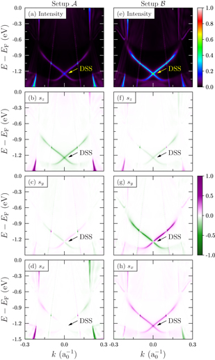
Figure 2. Spin-resolved photoemission from W(110) for wavevector k along  –
–  –
–  (kx). Circularly polarized light with a photon energy of 21.22 eV and with helicity σ+ impinges normally (setup
  , left column) or off-normally under ϑph = 45° (setup
  , right column) onto the surface. The spin-integrated intensities (top row) are resolved with respect to sz (second row), the 'Rashba component'sy (third row) and sx (bottom row). The green–white–purple color scale represents negative–zero–positive values. DSS marks the DSS.
Download figure:
Standard image High-resolution imageWhen changing the polar angle of incidence from 0° (setup  ) to 45° (setup
  ) in the xz plane, the intensity from the DSS increases (compare the DSS in figure 2(a) with that in (e)). Due to the off-normal incidence, one would expect an intensity asymmetry in the polar angle of detection (
 or
or  ). This effect is apparently minute for this surface state. The sz component of the spin polarization becomes reduced but sx becomes sizably large ((f), (h)). But more strikingly, the Rashba component is 'restored' (compare figure 2(g) with figure 1(c)); it shows the largest degree of spin polarization of all Cartesian components. More precisely: s = (− 43%,+87%, −19%) at (E,k) = (− 1.15 eV, 0.045 a−10) in (f)–(h). This implies that the degree of spin polarization is larger for the photoelectron (|s| = 99%) than for the initial state (sy = |s| = + 85% at the same (E,k) in figure 1(c)).
Setup  and in particular setup
  are suited to investigate the Rashba component of the surface state's spin texture. Although optical orientation affects the photoelectron's spin, the initial state's spin polarization can be distinguished from that due to optical orientation because there is no dichroism. In case of non-zero dichroism, the analysis can be extended as follows.
Spin-resolved experiments and calculations for dichroism provide a set of four spectra for a chosen spin quantization axis μ:


with the spin-integrated photocurrents I(σ±) ≡ I(σ±,↑μ) + I(σ±,↓μ). Here, we have decomposed the photoelectron's polarization into a part associated with the spin polarization of the initial state (is) and a part due to the optical orientation (oo), Pμ(σ±) ≡ Pisμ ± Pooμ. Pisμ does not change sign upon helicity reversal but Pooμ does. Thus, the differences


can be expressed as


If the measure Dcd of the circular dichroism vanishes, then Dooμ and Disμ allow to disentangle the origin of the spin polarization component μ. To make this point more clear, consider a 'non-dichroic' setup ( or
or  ). From symmetry considerations and calculated photocurrents, we find I(σ+,↑z) = I(σ−,↓z) and I(σ+,↓z) = I(σ−,↑z) but I(σ+,↑y) = I(σ−,↑y) and I(σ+,↓y) = I(σ−,↓y). Hence, Dcd = Dooy = Disz = 0 and Dooz ≠ 0 and Disy ≠ 0, indicating that sz is due to optical orientation and sy is due to the initial state.
We apply this approach to disentangle the spin polarization in the 'dichroic' setup  (
( –
–  –
–  azimuth). The circular dichroism Dcd is non-zero (intensity asymmetry of 51% at (E,k) = (− 1.15 eV, 0.05 a−10) in figure 3(a)) and asymmetric with respect to k. It is restricted to the DSS (DSS in figure 3(a)) because this is the electronic state with largest degree of spin polarization (figure 1(f)). The 'optical orientation' Dooμ provides for both spin components—z (b) and the Rashba component R (c)—a minor background (no change of sign for the DSS), in contrast to the 'initial state' differences Disμ (change of sign with k in (d) and (e)). Most strikingly, the absolute value is largest for DisR, as seen by the color saturation, suggesting that sR is mainly due to the initial-state spin polarization.
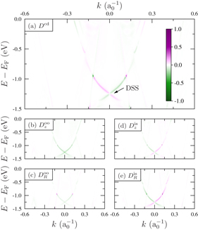
Figure 3. Dichroic photoemission from W(110) for wavevector k along  –
–  –
–  (setup
  , see text). Top: dichroism Dcd. DSS marks the DSS. Bottom: Dooμ and Disμ for the out-of-plane (μ = z, (b) and (d)) and the Rashba (μ = R, (c) and (e)) spin components. Parameters as for figure 2.
Download figure:
Standard image High-resolution imageEventually, we briefly address calculated spectra for unpolarized light (not shown here). Because unpolarized light is an incoherent superposition of left- and right-handed circularly polarized light, the photocurrent shows non-zero spin polarization only in the Rashba components; the components brought about by the optical orientation vanish. For the setups  and
and  , the spin-integrated and the sy-resolved intensities are very similar to those shown in figure 2; sx and sz are zero. The similarity holds also for setup
  : spin-resolved spectra compare well with the data shown in figures 3(d) and (e).
The spin–orbit interaction couples the orbital and the spin degrees of freedom. For the mirror-symmetric setups  and
and  , strict relations between the parity of the spatial part and the spin orientation of a wavefunction hold (confer (8) below). Thus, a measurement of the spin texture by spin-resolved photoemission allows to conclude on the parity of the initial state. It turns out that the spin texture of the Dirac surface state is connected with even orbitals, in agreement with the spectral density in which dz2 orbitals show the largest contribution [15, 16]. While such an entanglement procedure is comparably simple for W(110), it becomes complicated for chalcogenide topological insulators. Nevertheless, Zhu et al [44] have successfully analyzed spin texture and orbital composition of the Dirac surface state in Bi2Se3, using an analysis similar to that presented here.
3.3. (e,2e)
Complementary to photoemission, electron-induced two-electron emission is also a powerful tool for studying the spin–orbit-induced spin texture at surfaces. We demonstrate this for the case of the surface electronic structure of W(110) in the  –
–  –
–  azimuth, for which the scattering plane—xz—is a mirror plane of the semi-infinite crystal. Due to spin–orbit coupling, all four one-electron states have the schematic forms [40]

where 'even' and 'odd' indicate spatial parts of even and odd parity with respect to the xz plane of the semi-infinite crystal; the spinor parts are quantized with respect to the Rashba component μ = y.8 Since the primary and the two outgoing electron states are predominantly even, a selection rule [45] holds in good approximation: only the even parts of the valence states enter the (e,2e) matrix elements.
The left-hand part of figure 4 shows spectral densities for a bulk layer ((a), (b)) and the topmost surface layer (c)–(f) resolved with respect to spatial symmetry and spin. From panels (c)–(f) it is apparent that the branches of the DSS (labeled A and A' for positive and negative k2x, respectively) are almost exclusively even and spin-polarized. The surface state branches B, B', C and C' are also strongly spin-polarized but of predominantly odd parity.

Figure 4. (e,2e) from W(110) in the  –
–  –
–  azimuth. Left: spectral densities of a bulk layer ((a), (b)) and of the topmost surface layer resolved with respect to the Rashba spin component sR = sy and spatial parity (odd: (a), (c), (e); even: (b), (d), (f)), as indicated in each panel (c)–(f). Green symbols mark (E,k) positions of valence states studied in figure 5. Right: sketch of the (e,2e) setup (g) and associated spin-resolved (e,2e) intensities I+σ3σ4 ((h), (i)); E1 = 25 eV, k1 = 0, ϑ3,4 = 50°.
Download figure:
Standard image High-resolution imageFor normally incident primary electrons and emission at equal polar angles (figure 4(g)), the conservation conditions 4 turn the (e,2e) intensities Iσ1σ3,σ4 into functions of the valence electron energy E2 and its parallel momentum component k2x. These are shown for primary spin σ1 = + in figures 4(h) and (i). The parallel-spin intensity I+++ in panel (h) maps the spin-up even-parity surface state spectral density shown in panel (d), whereas the antiparallel-spin intensity I++− + I+−+ in panel (i) reflects the spin-down even-parity spectral density of panel (f). Since the mirror operation at the yz plane reverses all the spins, the intensities I−−− and I−−+ + I−+− are the mirror images of I+++ and I++− + I+−+, respectively.
The strong spin polarization of the DSS facilitates an investigation of the spin dependence of the exchange-correlation hole. For this purpose, an (e,2e) setup is suitable, in which the two emitted electrons have fixed equal energies E3 = E4 and variable surface-parallel momenta, k3 = −k4. By virtue of energy and momentum conservation (4) a surface state electron with E2 and k2 can then be selected by choosing for the primary electron E1 = E3 + E4 − E2 and k1 = −k2. As a typical example, we select the point (E2 = EF − 0.95 eV, k2 = (+ 0.142,0) a−10) on the spin-up branch of the DSS, which is indicated by the green dot in the left-hand part of figure 4. The primary electron with an energy E1 = 25 eV is incident with parallel momentum k1 = (− 0.142,0) a−10 (i.e. within the  –
–  –
–  azimuth at ϑ1 = 6.01° and φ1 = 180°). The emitted electrons have energies of E3 = E4 = 9.49 eV and surface-parallel momenta k3 = −k4.
The resulting (e,2e) momentum distributions Iσ1σ3σ4(kx,ky) in the plane  (with E3 = E4 in Hartree atomic units) of the outgoing electrons are shown in the left-hand part of figure 5. For primary spin up (σ1 = +), the parallel-spin intensity I+++ exhibits a large central depletion zone which is due to exchange and Coulomb correlation. The antiparallel-spin intensities are by far smaller. For primary spin down (σ1 = −), the antiparallel-spin intensities dominate and show a rather small central 'hole' which is due to Coulomb correlation only. The apparently spin-non-conserving intensities I+−− and I−++ rely on spin–orbit coupling in the primary and outgoing electron states; in fact they vanish in calculations without spin–orbit coupling in these states. The sums of the intensities Iσ1σ3σ4 over the outgoing-electron spin orientations σ3 and σ4 still exhibit, for primary spin σ1 = + , the large exchange-correlation hole and, for σ1 = −, the smaller correlation hole. Exchange and correlation effects can thus be disentangled in experiments without resolving the spins of the emitted electrons.

Figure 5. (e,2e) momentum distributions Iσ1σ3σ4(kx,ky) from W(110), with spins σi = ± along the y-axis as indicated in each panel. Left: valence electrons from the Dirac surface state with (E2,k2x) marked by green dots in figure 4. Right: valence electron from another surface state with (E2,k2x) marked by green squares in figure 4. For details see text.
Download figure:
Standard image High-resolution image
In the right-hand part of figure 5, we show analogous momentum distributions obtained for the valence electron surface state with E2 = EF − 0.10 eV and k2 = (0.65,0) a−10 (green square in the left-hand part of figure 4), which is selected using primary electrons with E1 = 25 eV incident at ϑ1 = 28.61° and φ1 = 180°. Again, the parallel-spin distributions exhibit an exchange-correlation hole which is larger than the correlation hole in the antiparallel-spin distributions.
A striking difference between the (e,2e) intensities from the DSS and those from the other spin-polarized surface state is that the former are strongest around the kx-axis, whereas the latter are very small along this axis. This is explained by the different spatial symmetry of the two states (see figure 4). For the outgoing electrons in the xz plane, the above-mentioned selection rule favors states with predominant even parity (like the DSS). For emission in planes other than xz, odd-parity parts of valence states also contribute to the intensities.
4. Concluding remarks
As we have shown by calculations of photo- and electron-pair emission, W(110) could serve as an important system for investigating experimentally spin–orbit effects in electron spectroscopies. Hence, it is obvious to study other non-magnetic metals with bcc structure. The strength of the spin–orbit interaction could be studied by comparing W(110) (Z = 74) with Mo(110) (Z = 42). Another topic is whether unoccupied strongly spin-polarized surface states exist at bcc(110) surfaces [46]; these could be investigated by spin-resolved inverse photoemission, two-photon photoemission or scanning tunneling spectroscopy [47–50].
Acknowledgments
We thank M Donath (University Münster) for very fruitful discussions. This work was supported by the Priority Program 1666 of the DFG.
Footnotes
- 6
The Jülich FLAPW code family: FLEUR. Forschungszentrum Jülich, D-52425 Jülich, Germany.
- 7
There is a single double-group representation, Σ5, for the point group 2mm (C2v in Schoenflies notation) [40, table B.10].
- 8
To be consistent with the usual nomenclature in (e,2e), we replace ↑ by + (spin up) and ↓ by − (spin down) in the following.