


Abstract
By backing or sandwiching a holey metal layer with or between isotropic dielectric slabs, additional peaks of transmission within the long-wavelength regime arise as a result of the induced transverse magnetic (TM) or transverse electric (TE) grounded dielectric modes. A similar control of the complex surface wave modes, and thus of the extraordinary transmission (ET) peaks, is demonstrated here via anisotropic slabs in the form of a fakir's bed of nails. However, it is shown that those ET peaks formed from TE modes are suppressed because of the inherent dispersion characteristics of the free-standing grounded pins. This allows the red-shifting of the ET for the polarization parallel to the larger in-plane period of the hole array, but unlike the dielectric isotropic slab configuration, the orthogonal polarization remains inhibited.
Export citation and abstract BibTeX RIS

Content from this work may be used under the terms of the Creative Commons Attribution-NonCommercial-ShareAlike 3.0 licence. Any further distribution of this work must maintain attribution to the author(s) and the title of the work, journal citation and DOI.
GENERAL SCIENTIFIC SUMMARY Introduction and background. The efficient transmission though arrays of apertures of size smaller than half the wavelength of the impinging electromagnetic wave was considered impossible until the discovery of the phenomenon coined as extraordinary transmission. Surface waves excited along the layer mediate in the process to couple the energy through the subwavelength aperture. These transverse magnetic (TM) surface waves are extremely sensitive to the characteristics of the material where the holey plate lies. Therefore, control of these waves, and thus, ultimately, of the extraordinary transmission can be attained by simply manipulating the surroundings of the hole array.
Main results. The introduction of dielectric slabs sandwiching the holey plate provide a simple way to manipulate TM surface waves. However, they may also support undesired transverse electric (TE) surface waves. The solution proposed is a 'hedgehog' hole array, i.e. a hole array loaded with a metamaterial wire medium slab. The result is that TM surface waves can be tuned at will, at the same time forbidding TE surface waves. The analysis is made in terms of a fakir's bed of nails, which behaves as an anisotropic uniaxial medium. The analytical results based on effective medium theory match perfectly with the full-wave simulations.
Wider implications. The ability to transfer energy through subwavelength holes opens the possibility of miniaturizing devices. Also, the structure proposed here holds promise in sensing applications, given the high dependence of the induced TM surface wave and the inhibited TE surface waves (and thus, of the extraordinary transmission) on the substance filling the space between pins.
 Figure. Transmission (in the logarithm scale) as a function of frequency and height of the metallic pins h when a plane-wave is incident normal to the holey layer decorated with an array of pins.
1. Introduction
The historical lack of terahertz applications is founded on the deficiency of suitable emitters and efficient sensors. In addition, terahertz waves are characterized by their complex control since approximations done for optical waves (light) or microwaves are no longer fully correct. However, the range hides important substances fingerprints for sensing and imaging applications. Therefore, terahertz frequencies are destined to become a new playground where interdisciplinary work may become more effective than in other regimes because of a non-well-established technology [1].
One of the most exemplary phenomena of the possible fruitful marriage between plasmonics and microwaves engineering is the extraordinary transmission (ET) through subwavelength hole arrays or across a tiny aperture flanked by corrugations [2]. This phenomenon was initially observed accidentally [3, 4] and later on was thoroughly studied by the optical community [2, 5]. Ebbesen et al gave this phenomenon the attention it deserved and successfully ascribed it to the excitation of surface plasmon polaritons [2, 5]. However, it was in microwaves/millimetre waves where it was revealed that any kind of complex surface waves would generate the same enhanced transmission [6, 7]. Furthermore, the Bloch nature of these complex surface waves on a periodic grating was emphasized in microwaves, where it was well known from the frequency selective surface field [8], and was revisited in optics afterwards [9]. In addition, the close stack of such kinds of holey layers made it possible to obtain a left-handed metamaterial in both optics, where it was first reported [10], and millimetre waves [11], where it was exploited for the first time in prisms [12, 13] and lenses [14, 15]. This back and forth shift between different points of view has enriched the field and has provided us with powerful techniques to design the electromagnetic response of subwavelength hole arrays [16–18].
Another field that has greatly benefited from inter- and multi-disciplinary approaches has been metamaterials [19]. Microwave engineering has provided the platform from which metamaterials have been able to grow exponentially over the last few years and move towards the visible. The great interest in this field relies on the ability to engineer microscopically artificial structures displaying designed effective macroscopic responses. One example of a metamaterial whose fundamental physics has been unveiled from a microwave engineering perspective and has made the jump to optical frequencies where it has been analysed from a plasmonic point of view is the metallic surface decorated with vertical metallic pins, also known for its resemblance to a fakir's bed of nails [20, 21].
Here, we explore the additional control given by engineered effective materials (metamaterials) to switch on/off ET peaks. In particular, we make use of the free-standing fakir's bed of nails. To this end, a holey metal layer attached to metallic pins in a hedgehog configuration is analytically and numerically analysed. In this way, the subwavelength hole arrays will be backed with or sandwiched between anisotropic uniaxial metamaterial slabs [20]. Like isotropic dielectric slabs, this allows the red-shifting of the ET based on transverse magnetic (TM) modes. However, in contrast to isotropic dielectric slabs, the metamaterial slab prevents the appearance of peaks related to transverse electric (TE)-trapped modes [7, 17, 18]. The analytical results found on effective medium theory are in good agreement with full-wave simulations.
2. Theoretical description
Let us consider a free-standing holey metal infinitely thin with square unit cell of in-plane period d, and aperture a ≪ d. Under normal incidence a standing TM complex surface wave with magnetic field horizontal with respect to the metallic plane (for a perfect electric conductor, it is a surface current) is excited, which produces a peak of transmission nearby, yet below the Rayleigh–Wood anomaly [7, 16, 22] frequency due to its resonant nature.
Let us now set aside the free-standing subwavelength hole array and focus on a grounded dielectric slab. This well-known waveguide supports TM (equation (1.1)) and TE trapped modes (equation (1.2)) with the following dispersion equations [23]:


where k0 is the free-space wave number, k∥ is the component of the wave vector parallel to the interface, εr is the relative permittivity of dielectric slab and h is the height of the slab.
When one combines both structures by, for instance, perforating tiny holes in the ground plane of the grounded dielectric slab, the inherent standing TM mode of the subwavelength hole array responsible for the ET resonance and the grounded dielectric slab modes coexist. The latter, which in the non-periodic situation is bound, is susceptible to 'resonant' coupling with the incident plane wave through the −1 diffraction order or space harmonic when the periodic hole array is patterned. The periodicity of the aperture array generates space harmonics whose spectrum can fall within the cone of light [7, 23–25]. These leaky space harmonics are those that couple to the outer plane wave. Thus, a dielectric-backed hole array supports both a TM mode that gives rise to the conventional ET resonance (like in free-standing hole arrays) as well as a TE mode that arises only when the dielectric placed fulfils some specifications, as explained in [7, 17, 18]. If we now mirror the structure along the xy plane, thus sandwiching the subwavelength hole array between slabs, only the grounded slab modes survive, and accordingly the peaks associated with them. The fact that a grounded dielectric slab supports TE trapped modes has been exploited to achieve ET peaks (coined anomalous ET) for hole arrays with a rectangular unit cell when the incident electric field is parallel to the short periodicity of the hole arrays [7, 17, 18, 26–28], and has served to design efficient electrically thin quarter-wave plates [29].
We can now imagine a slightly different scenario where the isotropic homogeneous dielectric slab is substituted by an anisotropic uniaxial medium. The characteristic equations take the following form [30]:


where ε∥ and εz are the components of the permittivity tensor parallel and perpendicular to the interface, respectively. Note that they lead to equations (1) (the isotropic homogeneous dielectric slab case) when ε∥ = εz = εr.
Finally, let us introduce as an artificial anisotropic uniaxial medium the free-standing (no dielectric host) fakir's bed of nails, which suffers additionally from spatial dispersion. From previous thorough studies [20], we know that this metamaterial has an effective permittivity
Furthermore, the dispersion relation for TM trapped modes is

where kp is the plasma wave number. Note that TE trapped modes are not expected since we are dealing with a free-standing case, i.e. without dielectric embedding [20]. And it is this feature what we will exploit in this work. Also note that the primary mechanism of the emergence of TM trapped modes is not the anisotropy of the slab or the spatial dispersion of the fakir's bed of nails, but the grounded configuration. Hence, they also develop for spatial-dispersion-free grounded dielectric slabs.
Now, we have all the ingredients to understand the consequences of using hedgehog subwavelength hole arrays: ET peaks formed from TM trapped modes will still be present. However, no TE trapped modes and their corresponding ET peaks should be supported. Therefore, the hedgehog subwavelength hole arrays will behave like dielectric-sandwiched subwavelength hole arrays, but with the suppression of TE trapped modes. This means that we will be able to red-shift the regular ET, while the anomalous ET, i.e. the orthogonal polarization, is inhibited, which is of primary importance for polarization-dependent quasi-optical devices.
3. Numerical results and discussion
In order to validate the line of reasoning of the previous section, finite-integration frequency-domain numerical calculations (CST Microwave Sutio™) are used. To this end, a unit cell and periodic boundary conditions along x and y are defined. This scheme allows us to describe the fields in free space as a combination of Floquet modes. Two different scenarios will be examined subsequently, depending on the in-plane periods of the hedgehog metal layer: square unit cell with dx = dy = d, and rectangular unit cell with dx ≠ dy. For the excitation of such structures, an incident plane wave with y-polarization and propagating along z will be considered. In order to achieve accurate results and accurately discretize the sample, a denser local mesh has been applied to the metallic pins. The minimum edge length in the simulation is 2.617 μm (which is related to the local mesh of the pins), whereas the maximum edge length is 202.8 μm.
3.1. Square unit cell (dx = dy = d)
For this study, both symmetric and asymmetric configurations are considered, see figure 1. The unit cell parameters are: in-plane period dx = dy = d = 0.5 mm, diameter of the aperture a = 0.15 mm, thickness of the layer t = 0, radius of the pins b = a/20 mm, height of the pins h and pitch p = 0.1 mm. Note that there are no pins on the hole so as to not disturb the field distribution within the hole. A perfect electric conductor for all metal structures has been chosen for the analysis since it is a reasonable approximation at the submillimetre-wave regime.

Figure 1. Sketch of the hedgehog subwavelength hole arrays together with the unit cell parameters: asymmetric (top) and symmetric (bottom) configuration. The hedgehogs are illuminated by a y-polarized plane wave at normal incidence.
Download figure:
Standard imageFigure 2 shows the transmission spectra as a function of h for symmetric and asymmetric configurations. Note that because of the step in h, the colour surface plots seem to be discontinuous, although this is just an artefact of the discretization. As was anticipated by the previous heuristic analysis, the asymmetric configuration displays an extra peak close to the free-space Rayleigh–Wood anomaly, see the inset of figure 2. This peak is associated with the free-space interface, see figures 3(a), (b), (e), (f) and (i), (j) for h = 0, 0.03 and 0.1 mm, respectively. Conversely, the other peaks at lower frequencies are linked to the grounded dielectric slab mode. Note that then, by introducing the fakir's bed of nails, the first enhanced peak can emerge at very low frequencies. Moreover, like isotropic-dielectric-slab-loaded configurations, this peak experiences a red-shift as a function of h, and higher-order modes manifest themselves from certain h onwards, which also red-shift with h. For h = 0.03 and 0.1, the first ET peak appears almost 2 and 8% red-shifted with respect to the unloaded subwavelength hole array configuration, respectively. From the field distribution shown in figures 3(c), (d) and (g), (h), one can identify the TM nature of the lower-frequency peaks associated with the grounded artificial slab. In addition, by inspection of the field in the xz-plane (not shown) we conclude that they are the (−1,0) space harmonic. The higher-order modes emerging from certain h onwards (and experiencing the red-shift with h) display the same TM field distribution in the yz-plane as these lower-frequency peaks. However, in the xz-plane, they are no longer uniform, but display the periodic pattern accounting for the (−1,±1) space harmonic.
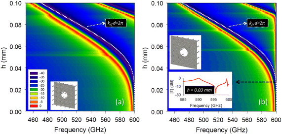
Figure 2. Transmittance (in the logarithm scale) as a function of frequency and h: symmetric (a) and asymmetric configuration (b). The dotted white lines show the analytical solution to the Rayleigh–Wood anomaly. Bottom inset in (b): transmittance close to the free-space Rayleigh–Wood anomaly for h = 0.03 mm.
Download figure:
Standard image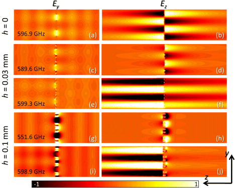
Figure 3. Electric-field distribution along the yz-cutting plane at the centre of the unit cell: free-standing subwavelength hole arrays (a, b); and asymmetric configuration h = 0.03 mm (c–f) and h = 0.1 mm (g–j). Right and left columns display Ez and Ey, respectively.
Download figure:
Standard imageIn figure 2, we also superimpose the solution of (4) such that k∥d = 2π. This condition comes from the periodicity of the structure and in the unperturbed state where the space harmonics do not interact with other space harmonics, it corresponds to the coupling of the incident plane wave to the trapped mode [24, 25]. However, it is known that the space harmonics do interact between them and this condition represents more precisely the minimum of transmission related to the Rayleigh–Wood anomaly and the excitation of the trapped mode happens slightly red-shifted to this condition. With this in mind, there is good agreement between the analytical work and the full-wave simulation.
It should be noted that neither the assumption of infinitesimal thickness nor the choice of a perfect electric conductor for all metal structures would affect the main results shown here. The introduction of a certain thickness leads to the emergence of an additional peak. This peak together with the zero-thickness case peak collapses into a single peak for a certain thickness and eventually the peak disappears for very thick layers [7, 16]. Meanwhile, if a certain conductivity is considered, a reduction of the transmission and a broadening of the peaks are expected, as the experimental work on ET indicate [17].
3.2. Rectangular unit cell (dx ≠ dy)
As was pointed out in the introduction, rectangular subwavelength hole arrays loaded with dielectric slabs support anomalous ET peaks [7, 17, 18, 26–29] associated with TE grounded dielectric slab modes. In this section, we investigate the potential for suppressing such modes by the array of pins.
For this analysis, we restrict ourselves to the asymmetric configuration. The unit cell parameters are: in-plane periods dx = 0.5, dy = 0.14 mm (thus, the incident electric field is parallel to the shortest in-plane period), the diameter of the aperture a = 0.07 mm, thickness of the layer t = 0, radius of the pins b = a/35 mm and pitch p = 0.02 mm.
The transmission spectra of this hedgehog for four different pin heights are plotted in figure 4. As can be expected from the literature, no ET peak is displayed for h = 0 in this frequency range [17, 18]. Consistent with our heuristic description in section 2, the transmission remains negligible even for definitely long pins, i.e. thick substrate, such as h = 0.5 mm. In addition, the transmission for dy = 0.22 mm and h = 0.1 mm (with the rest of the dimensions unchanged) is also plotted in the same figure 4(a). It is notable that two resonant peaks now emerge in the spectrum. In order to find the origin of these peaks, we can benefit from the numerical calculations that make the fields easily accessible. From figure 4(b) the TM nature of both peaks is clearly identified, since they do not have Hz (but do have Ez). And from figure 4(c), we can safely ascribe the peak at lower and higher frequencies to the (0,1) and (1,1) diffraction order of the TM complex surface wave supported by the grounded forest of metallic pins.
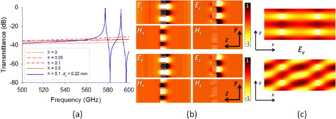
Figure 4. (a) Transmission spectra for dy = 0.14 mm (red curve) with h = 0 (dotted), 0.05 (dashed), 0.1 mm (dash-dot) and 0.5 mm (solid), and for dy = 0.22 mm with h = 0.1 mm (solid blue curve). (b) Electric and magnetic field distributions along the yz-cutting plane at the centre of the unit cell corresponding to the lower- (top) and higher-frequency ET peaks (bottom). (c) Ey distribution on the xy-cutting plane at 0.02 mm from the holey metal, within the forest of metallic pins, for the lower- (top) and higher-frequency peaks (bottom).
Download figure:
Standard image4. Conclusions
It has been shown analytically and numerically that anisotropic uniaxial effective metamaterials suffering from spatial dispersion bring additional degrees of freedom to control the enhanced transmission peaks supported by subwavelength hole arrays. Symmetric and asymmetric configurations for square unit cells (dx = dy) have been investigated to identify univocally the origin of the peaks to the TM modes excited at either interface. For rectangular unit cells (dx > dy) susceptible to supporting TE modes when the substrate is an isotropic dielectric, the fakir's bed of nails in its free-standing form (without the host dielectric) becomes an approach for preventing the excitation of those TE modes, and thus the ET peaks associated with them are no longer present. Moreover, under a proper design of the rectangular unit cell, complete suppression of TM and TE modes can be achieved below the Rayleigh–Wood anomaly for Ey polarization. The structure proposed here holds promise for biosensing applications as has been highlighted [21] at any frequency range. However, unlike [21], here the experimental setup is simpler since there is no need for the prism coupling block.
Acknowledgments
The authors acknowledge fruitful discussions with Professor Mário Silveirinha, Department of Electrical Engineering, Instituto de Telecomunicações, University of Coimbra, Portugal, and Professor Mario Sorolla and Rubén Ortuño, Millimeter and Terahertz Waves Laboratory, Universidad Pública de Navarra, Spain. This work was sponsored by the Spanish Government and European Union funds under contracts Consolider 'Engineering Metamaterials' CSD2008-00066 and TEC2011-28664-C02-01. MN-C is supported by Imperial College through a Junior Research Fellowship. PR-U is sponsored by the Government of Navarre via the program 'Formación de Tecnólogos' 055/01/11. MB is sponsored by the Spanish Government via RYC-2011–08221.
Footnotes
- *
In memoriam Professor Mario Sorolla.