


Abstract
We report on the Overhauser shift (OHS) of electric dipole spin resonance peaks in the reverse direction to that previously reported. Measuring electric dipole spin resonance in a double quantum dot, we observe two resonance peaks reflecting a Zeeman energy difference between the two quantum dots, and find that the dependence of the peak position on microwave power is different for each dot. The perturbation theory for hybridizing the flip-flop and photon-assisted tunneling mechanisms is discussed and is found to successfully explain the power dependence. This theory can also consistently explain the OHS in both directions, explaining the experimental results previously reported. Our results reveal the bidirectionality of OHSs and this is expected to play an important part in the development of effective nuclear spin squeezing techniques.
Export citation and abstract BibTeX RIS

Content from this work may be used under the terms of the Creative Commons Attribution-NonCommercial-ShareAlike 3.0 licence. Any further distribution of this work must maintain attribution to the author(s) and the title of the work, journal citation and DOI.
Corrections were made to this article on 11 February 2013. The acknowledgments section was corrected.
1. Introduction
Since the seminal proposal of Loss and DiVincenzo [1], many kinds of experimental and theoretical studies have been performed towards the realization of elemental quantum logic gates. Most studies have focused on the implementation of spin qubits in GaAs quantum dots (QDs). The progress made in this field has enabled us to access single electronic spins as well as nuclear spins. A recently emerging topic of interest is the interaction between electron and nuclear spins, which is the subject of a growing amount of research on the problem of electron spin decoherence.
Pioneering work on electronic transport in the presence of electron–nuclear spin interactions in QDs was carried out by Ono et al and Baugh et al. These authors measured the hysteresis of a leakage current as a function of the magnetic field and source–drain bias sweep direction in the Pauli spin blockade state using a vertical double quantum dot (DQD) [2, 3]. Their results showed that transitions between electron spin states in Zeeman levels can control nuclear spin states. In these experiments, a central role was played by electronic spin singlet and triplet states in a two-electron state, which governs the Pauli spin blockade [4]. Transitions between the electronic singlet and triplet states raise or lower the nuclear spin momentum in single quantum units. This is referred to as a flip-flop process, and is represented by a hyperfine interaction Hamiltonian.
The hyperfine interaction disturbs both the coherent precession of electron spins and the relative phase of a superposition of states [5], because the Gaussian ensemble of the small magnetic moments associated with nuclear spins becomes randomized due to thermal interactions with the environment [6]. Spin echo techniques have been used to decouple the nuclear spin-related dephasing process [7–9]. Increasing the number of compensation or rephasing processes has been shown to improve the phase precision [9]. The echo pulse sequence should be superimposed on the quantum gate manipulation sequence [8, 9] in order to minimize quantum gate errors; however, these techniques sometimes require a complicated signal set.
Dynamic nuclear spin polarization (DNP), and nuclear spin state preparation based on DNP, and Overhauser shift (OHS) [10] allow stable electronic spin evolution, and are efficient in removing quantum phase errors. A nuclear spin state preparation method and squeezing of the spin distribution has been experimentally investigated [11, 12] in the presence of a small magnetic field. For both polarization and narrowing of the nuclear spin distribution, an increase in the phase decoherence time was reported, which is desirable for stable manipulation of singlet–triplet qubits. Attempts have been made to extend these techniques using electron spin resonance (ESR) [13] and electronic dipole spin resonance (EDSR) [14–16]. The EDSR method manipulates single spins as single qubits [17, 18]. Experiments aimed at achieving DNP have already been reported using ESR [19] and EDSR [20], but so far no clear enhancement of the coherence has been reported. It is presumably difficult to keep the dragged Overhauser field constant while changing the excitation power and duration that is necessary for Rabi oscillation and Ramsey fringe experiments. The squeezing technique can narrow the nuclear spin distribution while keeping the average of the distribution constant. In this case, bidirectional polarization is required, because it allows us to keep the resonance point constant and to manipulate more nuclear spins than a single polarization sweep. However, only a negative OHS has so far been reported [19, 20]. In this report, we describe a positive OHS, an experimental analysis of its power dependence, and extend our discussion to a negative OHS.
2. Power dependence of the electronic dipole spin resonance peak position
We fabricated a gate-defined DQD on a GaAs/AlGaAs hetero-structure wafer [16, 17] (figure 1). At the GaAs/AlGaAs interface there is a two-dimensional electron gas (2DEG) sheet 90 nm below the surface. The 2DEG is laterally confined to form a DQD by applying appropriate voltages to the surface gate electrodes. A two-electron state is established by precisely tuning gate voltages. This state is described using the terminology (1,1), where the left and right values inside the parentheses represent the number of electrons in the left and right QDs, respectively. An external magnetic field, Bext, is applied parallel to the 2DEG plane. A cobalt strip placed on top of the structure is magnetized to generate a magnetic field gradient around the DQD. The in-plane component of the magnetic field gradient is position dependent so that an electronic spin in the left QD experiences a smaller magnetic field than that in the right QD. The out-of-plane field component has a gradient of ∼T μm−1 across each QD, and gives rise to the mediating magnetic field for EDSR. A microwave (MW) electric field is applied to the wide electrode to the left of the DQD through a high-frequency coaxial line connected to the sample by the capacitance in a bias tee [21] which keeps the averaged position of an electron constant, preserving the position-dependent ESR condition. The high-frequency signal causes an electron to spatially oscillate under the influence of the out-of-plane field gradient, and in the resonance condition, a pseudospin produced by a spin–orbital hybridization mechanism becomes flipped [22]. The EDSR condition is satisfied when the MW frequency and the Zeeman energy are consistent in each QD. Because the two QDs have different Zeeman splittings, we observe separate EDSR peaks for each QD [16].
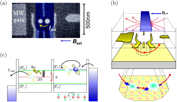
Figure 1. (a) Scanning electron micrograph of a device similar to the one measured. Gate voltages are applied to the surface gate electrodes (colored gray) to form a DQD. QD positions are indicated by circles. A high-frequency excitation signal is applied to the wide gate (MW gate) on the left. A micro-magnet (highlighted in blue) is placed on the surface and is electrically isolated from the gate metals by electron beam resist. A current Idot runs through the DQD in the resonance condition. (b) Schematic drawing of the device, showing the micro-magnet, gate metallization and DQD levels. The lower part of the figure shows a magnified view of the DQD layer, and the blue and red arrows represent the external magnetic field and the modulating magnetic field of the micro-magnet, respectively. Electronic spins (large circles with arrows) experience both of these magnetic fields in addition to the Overhauser field produced by nuclei (small dots with an arrow). (c) Energy diagram associated with the hybridized mechanism of flip-flop and photon-assisted tunneling. The flip-flop process takes place through the virtual states of |D±'〉.
Download figure:
Standard imageAt resonance, the electron states change among the four kinds of (1,1) states. Using the analogy of the Hubbard model, three triplet states |T−〉, |T0〉, |T+〉, and a singlet state |S〉 are the dominant eigenstates. The triplet state degeneracy is lifted due to the Zeeman effect in the presence of a magnetic field. |T0〉 and |S〉 have no magnetic moment, and are insensitive to magnetic field. In the Pauli spin blockade, the electronic spin state corresponds to either |T−〉 or |T+〉. A single spin of two spins can be selectively flipped by applying a resonance transverse field, which forms a hybridized state of |S〉 and |T0〉 [16, 23]. This hybridized state coherently changes into a doubly occupied spin singlet state |D〉 in one of the two QDs through the |S〉 state component and produces a finite current when a single electron escapes from the |D〉 state. This corresponds to the measured EDSR current (figure 1(c)). The empty right-hand QD is soon occupied by a new electron and a (1,1) state is again formed. This process is constantly repeated in the EDSR experiment.
The higher the MW power, the more frequent the EDSR events, and the larger the current that is produced. The peak height increases in proportion to the MW power, or the square of the amplitude of the MW electric field [17]. The peak position is also found to be affected by the MW power. Figure 2 shows the MW power dependence of the EDSR peak positions in an external magnetic field Bext, measured at a fixed MW frequency of 26 GHz. The magnetic field was swept from 4.775 T (higher than both resonances) to 4.675 T (lower than both) at the rate of 2 gauss s−1 for each trace. The MW power was switched off when we sweep back the magnetic field in the opposite direction in order to avoid any unintended OHS [20]. The MW power was changed with a constant step size from one trace to the next. Two EDSR peaks for the left and right QDs are seen at resonance magnetic fields of BL0 and BR0, respectively [16], with the low-field peak being stronger. We assign the larger peak at BL0 to the left QD on the basis of numerical simulations of the field distribution of the micro-magnet, which indicate that the left QD should have a lower resonance field.
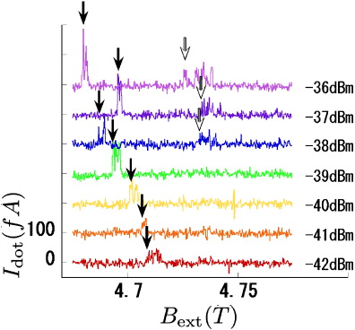
Figure 2. Power dependence of EDSR peaks. The resonance frequency is 25.6 GHz. Each spectrum is shifted in the vertical direction for clarity. The number beside each spectrum represents the input MW power. As the MW power increases, the low-field peak shifts more than the high-field one.
Download figure:
Standard imageBoth peaks show a power-dependent position shift in the direction of the external field sweep. The larger peak position BL0 shifts by 29 mT, more than the smaller peak position BR0, by 7 mT in the MW power range. These values are obviously larger than the local fluctuation field by the random nuclear spin distribution already reported in [5, 27].
A similar drag was obtained by Vink et al [19] in which the external field was repeatedly swept backwards and forwards. These authors have resolved the dragging effect with just one peak into contributions from two ESR processes [29] but did not show the power dependence of the both directional locking effect. Because the left QD is closer to the MW gate (figure 1), a central role is presumably played by the MW electric and magnetic fields. Note that this shift is not due to the MW-induced shift of the dot position, as no significant difference in the stability diagram with and without MW applied off resonance partially was shown in our previous report [17].
3. Master equations' approach
We describe the system using the simplified model shown in figures 1(b) and (c). The local field experienced by electrons in each QD can be described as Bext − Bmi − Bni (i = L,R), where the indices L and R indicate the left and right QDs, respectively. We take the magnetic field axis and the spin quantization axis to be the line joining the two QDs from left to right. The terms Bmi(>0) and Bni represent the magnetic field shifts due to the micro-magnet and the nuclear spin Overhauser field, respectively. We previously estimated their values to be 80 and 90 mT, respectively [16]. We define Bni = A〈Iiz/N〉, where N is the number of nuclei in contact with an individual electron in each QD, A(>0) is the hyperfine coupling constant and 〈Iiz〉 is the overall average nuclear spin momentum. Ignoring dynamical polarization effects, the mean Overhauser field difference 〈BnL − BnR〉 is zero. The resonance condition is satisfied for  , where ω is the MW frequency. The resonance magnetic field is larger for the right QD than for the left QD, because BmR > BmL ≫ BnR,BnL.
For simplicity, we consider the dynamics of the flip-flop process in a single QD. This can be extended to both QDs by changing the scaling parameters for MW electric field efficiency (see below). We consider that the dynamic OHS is due to a feedback mechanism mediated by the hyperfine interaction, in which the flip-flop terms play the most important part. When a flip-flop occurs, an electronic and a nuclear spin turn in opposite directions by one quantum unit to conserve the total spin angular moment. The Zeeman energy for electronic spins is much larger than that for nuclear spins under such a strong magnetic field and this large energy mismatch can suppress the flip-flop process. Therefore, some intermediate mechanism is required to compensate for this energy gap [24, 26]. We propose that photon-assisted tunneling can explain the large energy discrepancy and the power dependence; in other words, a flip-flop takes place by the absorption and emission of a single photon.
3.1. Photon-assisted tunneling
Photon-assisted tunneling is to date well understood by a perturbation theory [25, 28]. We simply follow the results discussed in these references. In our experimental setup, the source–drain bias is much larger than the single photon energy ℏω, so photon-assisted tunneling rarely occurs between two QDs and reservoirs. The tunneling rate between DQD and reservoirs Γout(≅Γin) is larger than single photon energy ℏω, and the inter-dot tunneling coupling γt is less than the single photon energy [16, 17]. In this case, the inter-dot tunneling occurs in a non-adiabatic way under the MW electric field. When the inter-dot energy detuning is zero and the energy levels in each QD are aligned, there is a resonant charge transition between |S〉 and |D〉 with the transition rate of γtJ20(eV /ℏω), where Ji(x) (i = 0,±1,±2,...) is the ith order Bessel's function and V is the inter-QD high frequency voltage drop across two dots [28]6. Note that without MW application, the resonant tunneling rate coincides with γt. In MW electric field, the inter-dot tunneling process is accompanied by the photon energy absorption and emission processes. The |D〉 state is split into subband states, |Dn〉 with the n-photon absorption process and |D−n〉 with the n-photon emission process. For simplicity, we restrict our theory to the case of n = ± 1, which is the dominant case in our theory. The tunneling rate from |S〉 to |Di〉 is written as γtJi(eV/ℏω). By the analogy of the Hubbard model, we can consider the hybridized states |D±'〉 of |S〉 and |D±1〉.

The energy associated with |D+'〉 and |D−'〉 is ℏω and −ℏω, respectively. They are aligned with the energy of |T±〉.
3.2. Dynamic nuclear spin polarization
We define the ascending and descending nuclear spin flip-flop rates as W⇑→⇓ and W⇓→⇑, respectively. In the descending process, the electronic spins begin in the |T−〉 state whereas in the ascending process they begin in the |T+〉 state (figure 1(c)). The flip-flop process flips an electron spin and counter-flips a nuclear spin. By Fermi's golden rule, we calculate these rates as W⇑→⇓ = ρT−|〈D+'||T−〉|2Γout and W⇓→⇑ = ρT+|〈D−'||T+〉|2Γout, which is followed by the products of the expressions W⇑→⇓ = ρT−·χγtJ2−1(eV/ℏω)/E2D1'/T−·Γout and W⇓→⇑ = ρT+·χγtJ21(eV/ℏω)/E2D−1'/T+·Γout, where ρT+(T−) and χ = Γ2out/(ω/2π)2 × A2/N represent the density matrix for |T+〉(|T−〉) and the coefficient for the flip-flop process, respectively. Here we adopted the Gaussian approximation for the distribution of nuclear spins to calculate the off-diagonal component of the density matrix, or the flip-flop term in the Hyperfine interaction. Therefore,  .
.
The nuclear polarization rate is described by the following feedback equation [3, 19]:

where p±3/2 is the probability of the nuclear spin state being Iz = ± 3/2, and is assumed to be p±3/2 = 1/4 [3], and Tn1 is the relaxation time of the nuclear spin. We can write

with ED−1'/T+ = −ED1'/T−≅gμeBext − ℏω − A〈Iz〉, where  is a fitting parameter. For simplicity, we omit the contribution to the magnetic field of the micro-magnet. By solving the standard master equations using a density matrix, we obtain ρT+ − ρT− = R(γ−1t + γ−1ESR), where R and γESR are the electronic spin relaxation rate and the transition rate of the densities of singlets and triplet. Because we do not repeatedly modulate the magnetic field as was the case in [19], we expect no squeezing effect [10], which can enlarge γESR. γESR is exactly a quadratic function of the Rabi frequency, and therefore of V [17]. The effect of the electric field is larger for the left QD than the right QD, and this can be expressed in terms of a scaling factor VL,R0. For a fixed transition rate γ0ESR, a stronger electric field is required at the right QD than at the left QD. γESR can be expanded as γ0ESR(V/VL,R0)2 with VL0 < VR0 [17].
Equation (3) shows that spontaneous polarization of nuclear spin occurs under the EDSR condition (figure 3(a)). The stable point is calculated by balancing the first and second terms in equation (3). For a magnetic field much higher than that for the EDSR resonant condition, the average nuclear polarization is zero. When the magnetic field is gradually decreased to a value closer to the resonance value, the nuclear spin polarization becomes larger because the system stays in the spin blockade state, where the |T+〉 state is dominant, and ρT+ ≈ 1. Because the flip-flop rate is slightly suppressed by the energy mismatch between |D±'〉 and |T∓〉, there is no resolvable signal, and it takes time to achieve the maximum polarization. As the magnetic field further decreases, there is a finite probability of the existence of the |T−〉 state. In this case, the feedback mediated by the spin flip-flop process acts to depolarize the nuclear spin bath because the probability ρT− increases, and the total nuclear spin 〈Iz〉 decreases. The equilibrium point can be determined graphically as the point at which the decay and polarization lines cross each other in figure 3(a) [19]. When the magnetic field is further decreased, the polarization rate becomes smaller, and finally the flip-flop rate significantly exceeds the sweep rate and the feedback mechanism no longer works. Simultaneously, the EDSR resonance is turned off.
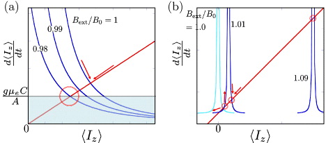
Figure 3. Flip-flop rate versus polarization 〈Iz〉. The curves represent the flip-flop trajectories and the straight line through the origin represents relaxation of the nuclear spin. (a) The numbers indicate the ratio of the magnetic field shifts. When the flip-flop rate is larger than the relaxation rate, 〈Iz〉 increases up to the crossing point. If the polarization passes the crossing point, 〈Iz〉 decreases towards the crossing point [19]. These feedback behaviors are graphically shown by the arrows. The movement of trajectories in 〈Iz〉 changes to a smaller value. (b) The movement of trajectories in 〈Iz〉 changes to a larger value. Initially, there is only a solution at Bext/B0 = 1.0. When the external field is increased, there appears another crossing point for the smaller 〈Iz〉 than the center of the trajectory at Bext/B0 = 1.01. One on the higher magnetic field gives the stable solution and the other gives the unstable point. The instability is shown by the arrows, as well.
Download figure:
Standard imageHere, we define a magnetic field sweep rate C (gauss s−1). We can determine the lower bound of the magnetic field shift, δBb ∼ Bext − ℏω/gμe, as the crossing point of three lines in figure 3(a). In the present case, the inter-QD voltage drop, V , is so small that we can expand the Bessel function with respect to V . Finally, we obtain
with parameters  and
and  . When V is less than V0, the magnetic field shift is almost constant, while it increases linearly for larger values of V . We can compare the derivative of equation (4) with respect to V and find the ratio of two lines as the ratio of VL0 and VR0. In our previous work, we determined this ratio to have a typical value of ∼1.6. In our results (figure 2), the larger peak position BL0 shifts more than the lower peak position BR0. The shift is a few times larger for the higher peak than that for the lower peak, which is of good consistency with our theoretical prediction. The absolute value of OHS is also predicted by using realistic parameters. By putting the typical value of the parameters [17]; i.e. ω/2π = 26 GHz, γt = 1.6 MHz, Γout = 30 GHz, γESR = 1 MHz (this is the case for a Rabi frequency of 10 MHz and the decoherence time of 10 ns [23]), A = 6 T, N = 105, R = 1 kHz and assuming J1(eV /ℏω) ≈ 0.1, we estimate that the typical value for OHS is gμeδBb/ℏω ∼ 0.1%, which is a reasonable value compared with the experimental result.
3.3. Negative drag of the Overhauser field
Finally, we consider the case when we sweep up the magnetic field in figure 3(b), which is the situation often reported to show DNP effect [19, 20]. Figure 3(b) shows that the larger the magnetic field, the larger the averaged nuclear spin 〈Iz〉 (see figure 3(b)). At some moment, there appears another crossing point of the perturbation trajectory and the decay line of nuclear spin at a smaller value of 〈Iz〉 like the case shown by label Bext/B0 = 1.01. It is remarkable that this crossing point gives the unstable solution; when the average nuclear spin value scatters temporarily to be more negative (positive), the acceleration rate decreases (increases) to a point at the more negative value.
When the external field is increased the stable and unstable points approach. It is interesting to consider the case where the distance between the two solutions is of the order of the standard deviation of the nuclear spin distribution, indicated by label Bext/B0 = 1.09 in figure 3(b). For simplicity, we assume a constant value of standard deviation nuclear spin distribution, which can be squeezed in DNP [19]. Under this condition, the feedback at the stable solution point is disturbed by the fluctuation. The value of 〈Iz〉 is stable within the range of the standard deviation ±δIz; therefore the trajectory of the stable point can hop to the point of the unstable solution, which terminate the feedback process. Intuitively, the stable feedback cycle of EDSR and flip-flop process is disturbed by the nuclear spin fluctuation.
By equilibrating the difference of two values of 〈Iz〉 for stable and unstable positions, we approximately derive

Here we assumed that the flip-flop rate at the stable point is the same as the rate at the unstable point. This assumption may be reasonable when the two points are very close with respect to 〈Iz〉. In this solution, the amount of OHS is constant around the smallest power of MW electric field, because γL,RESR∝V2, as was discussed in the previous section. This function gives a linear dependence of OHS with respect to the MW power, which saturates the maximum amplitude of OHS due to the local maximum of the Bessel's function. As is the case for the positive drag, the faster the Rabi frequency, the larger the amount of OHS. The maximum amount of OHS is calculated when the first-order Bessel's function is maximum. Using the parameters discussed above, AδIz ∼ 3 mT and Tn1 ∼ 10 s the typical amplitude of the OHS gμeδB/ℏω ∼ 40%. This value is larger than that for the shift in the opposite direction discussed in the previous section but the order of the shift is comparable with the experimental results, which are previously reported [19, 20].
Combined with the previously reported negative OHS [19, 20], the results of the present study imply that the Overhauser field can be dragged in both directions. One of the most promising applications of this would be nuclear spin state preparation [10], in which it is necessary to polarize and depolarize the nuclear spin bath many times by keeping the system at resonance. Before this technique can be realized in practice, further detailed studies, such as an analysis of stochastic equations, are required. However, we believe that the present results represent a key step towards spin squeezing, and therefore open the door to obtaining a solution to the decoherence problem.
4. Conclusion
In the present study, we investigated the MW power dependence of the EDSR peaks for a DQD system. The peak positions were found to shift to lower magnetic field, which is in an opposite direction to that reported previously. This shift is known as the OHS, and has a positive polarization direction, which means that the average nuclear spin momentum increases. The mechanism giving rise to the observed effect is explained using a standard first-order perturbation method. Combined with the previously reported negative OHS, a concrete method for squeezing a random nuclear spin distribution in a single spin qubit system is now possible [10].
Acknowledgments
TO acknowledges fruitful discussions with R Sakano and M Rudner. Part of this work was financially supported by ERATO-JST (080300000477), JSPS MEXT Grant-in-Aid for Scientific Research on Innovative Areas (21102003), Funding Program for World-Leading Innovative R&D on Science and Technology (FIRST), and the Project for Developing Innovation Systems of the Ministry of Education, Culture, Sports, Science and Technology (MEXT), Japan. We acknowledge funding from the Intelligence Advanced Research Projects Activity through the Army Research Office.
Footnotes
- 6
The stabilization process is described using the analogy of the interdot photon-assisted tunneling process in the case when the (1,1) and (2,0) electron states are separated by the energy corresponding to a single photon ℏω.