
Abstract
Along with advancements in superconducting technology, especially in high-temperature superconductors (HTSs), the use of these materials in power system applications is gaining outstanding attention. Due to the lower weight, capability of carrying higher currents, and the lower loss characteristic of HTS cables, compared to conventional counterparts, they are among the most focused large-scale applications of superconductors in power systems and transportation units. In near future, these cables will be installed as key elements not only in power systems but also in cryo-electrified transportation units, that take advantage of both cryogenics and superconducting technology simultaneously, e.g., hydrogen-powered aircraft. Given the sensitivity of the reliable and continuous performance of HTS cables, any failures, caused by faults, could be catastrophic, if they are not designed appropriately. Thus, fault analysis of superconducting cables is crucial for ensuring their safety, reliability, and stability, and also for characterising the behaviour of HTS cables under fault currents at the design stage. Many investigations have been conducted on the fault characterisation and analysis of HTS cables in the last few years. This paper aims to provide a topical review on all of these conducted studies, and will discuss the current challenges of HTS cables and after that current developments of fault behaviour of HTS cables will be presented, and then we will discuss the future trends and future challenges of superconducting cables regarding their fault performance.
Export citation and abstract BibTeX RIS

Original content from this work may be used under the terms of the Creative Commons Attribution 4.0 license. Any further distribution of this work must maintain attribution to the author(s) and the title of the work, journal citation and DOI.
1. Introduction
Although superconductivity was discovered in the last century [1, 2], its application in power system apparatuses was not economically possible until the discovery of high-temperature superconductors (HTSs). Ever since, many research and development activities have been conducted to integrate HTS technologies in power systems aiming the enhancement of generation, conversion, transmition, and even storing the electrical energy with low loss [2].
HTS transformers [4–7], HTS machines [8–13], superconducting fault current limiters (SFCLs) [14–16], superconducting magnetic energy storages (SMESs) units [17, 18], and HTS cables [19–22] are the most common application of superconductors in power systems. HTS materials would also play a key role in upcoming power grids and cryo-electrified transportation units (CETU) [23]. It was anticipated that HTS cables will be fully commercialised by 2030 [24].
HTS cables have numerous advantages against their conventional counterparts, such as extremely low resistive losses, 5× to 8× compacter structure, fault current limiting capability, etc. [25]. Given the potential role of the HTS cable in future, acquiring a complete understanding of their behaviour under different circumstances is crucial. The occurrence of faults, failures, and abnormalities in the cable itself or in the power system to which the cable is connected, can jeopardise the appropriate functionality of HTS cables. Thus, the fault performance study of HTS cables is vital to analyse the electromagnetic coupled with thermomechanical characteristics of HTS cables. High fault currents, i.e., low impedance faults can dramatically jeopardise the safe operation of HTS tapes and without a proper protection or a fault current limiter device, the burnout of HTS tapes is most likely. In some specific HTS cables, former is designed as a bypass path to keep HTS tapes safe in the case of short circuit events or SFCLs are located in series with HTS cable to supress the fault current. By passing fault current through the former layer and superconducting layer, an excessive heat load will be imposed on the cooling system. Extra heat load increases the temperature of the cable which should be compensated, otherwise, failure of cable or tapes is inevitable. As a result, reliability and availability issues put the stability of the power grid in danger. Therefore, fault analysis of HTS cables plays a significant role in achieving a power grid with high safety, stability, and reliability [26].
During the last years, many studies have been carried out to investigate the behaviour of the HTS cables under faults or transient states. These studies can be classified according to many considerations, such as the topology of understudied cables, voltage level, types and methods of fault and transient study, and the operation regime of the cables (AC or DC). In this paper, a review is presented for all conducted efforts on fault analysis of superconducting cables. Firstly, a summary on the most important projects of HTS cables is presented and after that different topologies and structures of the HTS cables are discussed. Existing challenges of HTS cables related to their fault analysis are also presented afterwards. These are categorised in two groups: those related to fault performance and those related to grids. After reviewing these challenges, an overview on the conducted studies is performed to analyse their methods for dealing with the proposed challenges. Finally, future trends on the fault analysis and also transients of the HTS cables is discussed to light up the coming future for HTS cables.
2. A brief history of developments and advances of HTS cables
One of the earliest efforts on the prototype of HTS cables was conducted on a 30 meter-long 12.4 kV cable, in Georgia, USA, year 2001 [27]. A few months after that, the Italian research group of Pirelli cables and systems in collaboration with the electric power research institute and the USA department of energy, have tested a 50 meter-long/115 kV AC HTS cable [28]. After these prototypes, many investigations were carried out on AC HTS cables but their lengths hardly reached to 100 meters [3]. Eventually, a 34.5 kV HTS cable with a length of 350 meters and a nominal current of 800 A was tested in Albany, USA [29]. After that American superconductors fabricated and tested a 600 m long HTS cable with 138 kV operating voltage that was installed in Long Island, New York to deliver 574 MVA power [30]. Afterwards, many countries contributed to fabricating, testing, and installing the AC HTS cables [3]. Among them, the Ampacity project is among the most important projects that used a 10 kV/1 km HTS cable to transmit 40 MVA in Essen, Germany [31]. The project was a collaboration between RWE Deutschland AG, as client, Karlsruhe Institute of Technology, as overall controller, Leibniz University Hannover, and Nexans which aimed to replace the 110 kV conventional cables with the aforementioned HTS cable. Another German project were initiated lately in Munich, known as SuperLink with a 12 km/110 kV HTS cable, as one of the longest HTS cables ever tested [32].
Apart from investigations and projects on AC HTS cables, researchers have also studied DC cables. The first effort was accomplished in 2011 on a 200 m DC cable with 10 kV voltage and 2 kA current [33]. After that institute of electrical engineering and Chinese academy of sciences have installed a 1.3 kV and 10 kA DC cable in 2012 [34]. Another DC HTS cable was installed in South Korea in 2015 with a 3.13 kA current and 80 kV voltage ratings [35]. St. Petersburg project was another DC HTS cable project with 2.5 km length and 20 kV operating voltage [36].
Table 1 presents information about the voltage level of all projects on AC and DC HTS cables. This information has been extensively presented in [3].
Table 1. A list of most important projects and researches on AC/DC HTS cables, adopted from [3].
| Project named/City name | Year | Country | Voltage Level (kV) | Current (kA) |
|---|---|---|---|---|
| Carollton | 2000 | USA | 15 | 1.25 |
| Albany | 2006 | USA | 34.5 | 0.8 |
| Long Island | 2008 | USA | 138 | 2.4 |
| Ampacity | 2013 | Germany | 10 | 2.3 |
| Yokohama | 2010 | Japan | 66 | 1.75 |
| Icheon | 2011 | S. Korea | 22.9 | 1.25 |
| CASER | 2011 | Japan | 10 (DC) | 2 |
| IEE CAS | 2012 | China | 1.3 (DC) | 10 |
| KEPRI | 2014 | S. Korea | 80 (DC) | 3.25 |
| St. Petersburg | 2020 | Russia | 20 (DC) | 2.5 |
| SuperLink | 2021 | Germany | 110 | 3.2 |
3. Categorising different types of superconducting cables
3.1. According to electromagnetic structure
The diversity in the application of superconducting cables eventuates in different types and structures for these cables. This variety in topology, types of dielectric, and cooling structure affect their overall behaviour. For instance, dielectric types and materials will impact the heat transfer rate in a cable during a fault; or even the topology of the cable is an important factor for determining the electro-magneto-thermal behaviour of an HTS cable.
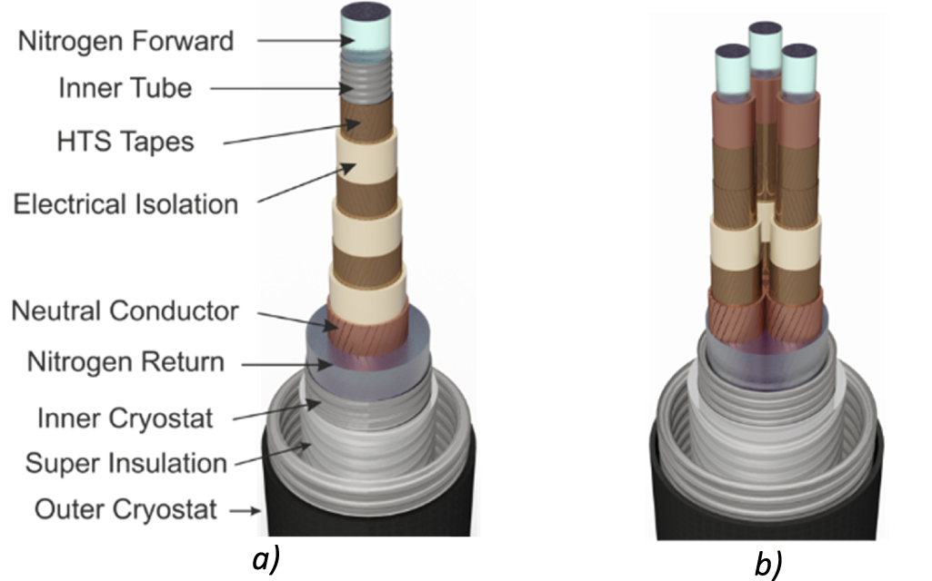
- Tri-axial HTS cables: Cables with such topology have smaller sizes and compacter structures. Consequently, the cooling system needs to cool down less area in comparison to other topologies. This leads to increase in the efficiency of the cable and cooling unit. However, balancing the non-uniform current distribution is a difficult manufacturing task in these types of HTS cables [37, 38]. This is the case for both AC and DC HTS cables and a typical structure of these cables is shown in figure 1(a).
- Co-axial HTS cables: In this configuration, each phase does not lay on the same axis with other phases. Thus usually, the number of HTS tapes is the same in each phase, which leads to a balanced current distribution in each phase. However, the magnetic field in this structure might be higher than the tri-axial type. As a result of this, the employment of the superconducting shield layer is inevitable in these cables that leads to a high fabrication/manufacturing cost. Another drawback of this topology is their bigger size in comparison to tri- axial types [39]. They are usually used for the AC high voltage cables/systems and this type of cable is shown in figure 1(b).
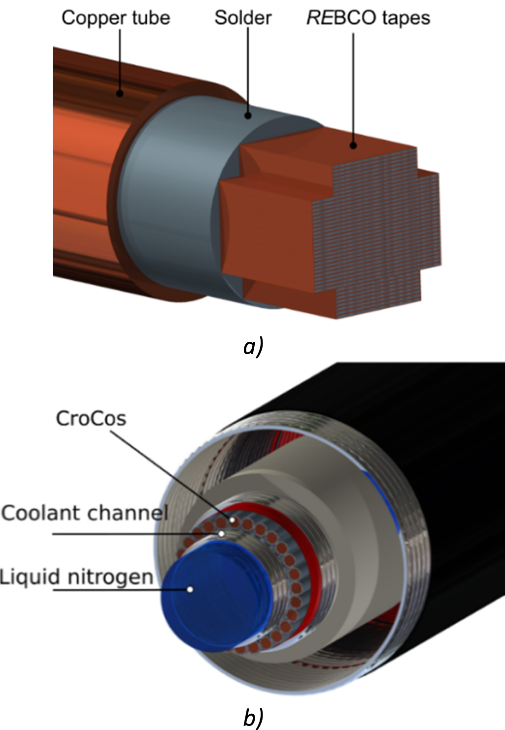
- Cross Conductor Cables (CroCo): In this design, individual tapes are soldered together and embedded into a solder matrix to form a single strand. The concept is illustrated in figure 2(a). By utilising two different tape widths, the HTS CroCo aims to maximise the HTS cross section within the round matrix cross section. In an additional process, the round strand can then be jacketed by, for example, a copper tube to improve thermal and electrical stability in case of a fault current event. The whole DC cable is then composed of several CroCo strands placed inside the cryostat with a dielectric material. Figure 2(b) illustrates the final schematic conceptual design [40].

Figure 1. Overview of the mostused types of HTS cable and structure (a) tri-axial three phase HTS cable, (b) coaxial three-phase HTS cable.
Download figure:
Standard image High-resolution image
Figure 2. (a) Schematic of a single HTS CroCo strand using REBCO tapes of two different widths in a round solder matrix with an optional copper tube and (b) schematic of a conceptual DC HTS cable design with all components present.
Download figure:
Standard image High-resolution imageThere are some other types and structures of HTS cables besides the aforementioned ones [41]. Among them, there are two important types, which are listed as follows:
- Conductor on round core (CORC) Cabling Method: CORC is a novel configuration of cables [42] applied to HTS power cables [43] or to build large magnets [44]. This type of cabling method is illustrated in figure 3.
- Roebel assembled coated conductor (RACC) was first introduced to conventional conductors of electrical machines and transformers to reduce Eddy current losses, but later such concept was applied to HTS cables. In [45] a complete discussion on this cabling method is presented. A schematic of an RACC cable is displayed in figure 4.

Figure 3. 3D presentation of CORC HTS cable, with the permission of the Advanced Conductor Technologies (LLC).
Download figure:
Standard image High-resolution image
Figure 4. Schematic of Roebel cable consisting of five tapes [40].
Download figure:
Standard image High-resolution imageSome other cabling methods are also possible, i.e.:
- Coated conductor Rutherford cable [46],
- Cable in conduit conductor [47],
- Round strands composed of coated conductor tapes [48]
- A specific type for Swiss Plasma Centre [49].
- Quasi-isotropic strand [50, 51]
3.2. According to dielectric type
HTS power cables are also classified according to the type of dielectric:
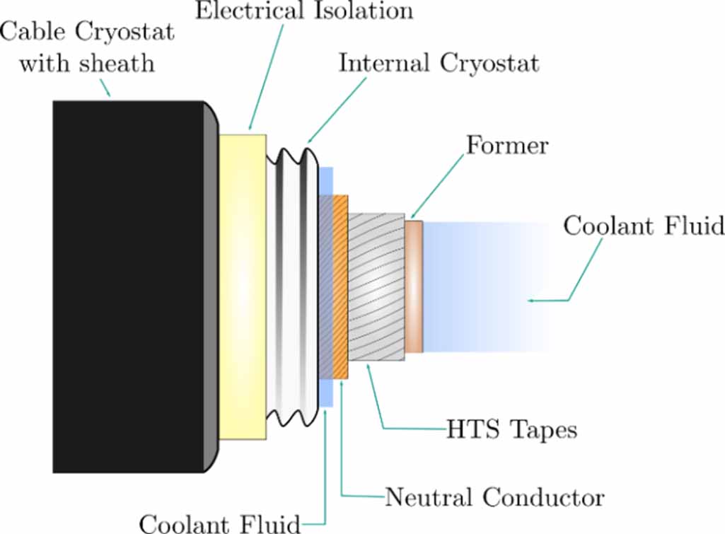
- Cold dielectric (CD): Electrical insulation layers of CD HTS cables are kept at cryogenic temperature. In this type of cable, the cooling area is way larger than warm dielectric (WD) types and this leads to higher heat load and cooling power. However, leakage current is negligible and so the loss is minimised. The used dielectric in this type is usually polypropylene laminated paper (PPLP) [52]. The typical structure of CD HTS cables is presented in figure 5.
- WD: In this type, the dielectric is placed outside of the cryogenic medium while formers, superconductors, and shield layers are inside of the cryogenic fluid. WD HTS cables require lower cooling power in comparison to CD HTS cables. The type of electrical insulation used in these cables is not the same as CD cables and is usually more expensive. The most common type of material used for this purpose is all different types of extruded dielectrics like cross-linked polyethylene (XLPE). Another drawback of WD HTS cables is their higher inductances and capacitances in comparison to CD cables [53]. It should also be mentioned that WD designs cannot be applied to tri-axial cables. The typical structure of WD HTS cables is presented in figure 6.

Figure 5. A schematic of cold dielectric HTS cable.
Download figure:
Standard image High-resolution image
Figure 6. A schematic of warm dielectric HTS cable.
Download figure:
Standard image High-resolution image3.3. According to cooling structure
HTS cables can be classified based on the configuration of their cooling system and the structure of cryostat pipes and return path, as follows:
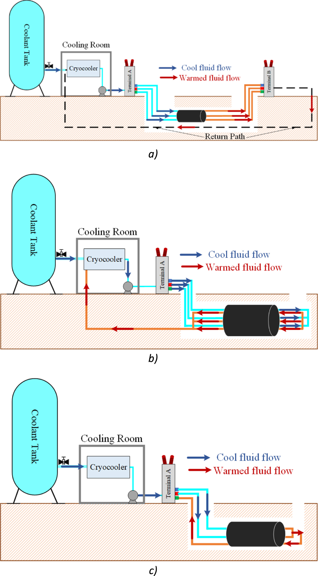
- Three-Separate: In this type of cooling structure, each phase or layer has an inlet. However, the return path of coolant fluid is identical for all phases/ layers, that is usually placed in the centre of the first former of cable [54]. This configuration is shown in figure 7(a).
- Triad: In this design of cryostat and cooling structures, each phase has separate inlet and outlet paths for coolant fluid [55]. Triad cooling system can be observed in figure 7(b).
- Triaxial: Triaxial structure is the most compact structure among all. In this type, two phases are considered as inlet passages and usually outer phase is considered as a return path [55]. Figure 7(c) demonstrates this structure.

Figure 7. The different cooling systems of HTS cables (a) three-separate cooling system (b) triad cooling system (c) triaxial cooling system.
Download figure:
Standard image High-resolution imageSo far, different classifications of superconducting cables have been analysed in detail. It must be mentioned that there are some factors which could affect the fault characteristic of HTS cables. The first group of these factors are related to the fault and grid parameters like fault resistance, ground resistance, fault duration, fault type and level of short circuit. These factors change the first peak of the fault current and as a result of this thermal characteristic of HTS cables during fault also changes. They are usually stochastic and depend on many other factors of grid or even the environment. The second group of parameters are related to the cable itself. For instance, the value of the maximum temperature in an HTS cable during a fault depends on the structure, geometry, type of dielectric, shielding, heat load and even performance of cooling systems. These parameters must be considered during the design phase of the HTS cables and before their implementation in power system.
4. Challenges and solutions
4.1. Challenges on the characteristic of HTS cables against faults
By the occurrence of a short circuit fault, and if the cable is not properly designed and/or well-protected, burnout, deformation, or mechanical collapse of HTS tapes are possible. So, fault parameters and their impact on the fault performance of HTS cables must be completely studied before implementing these cables into power grids or a stand-alone power system.
Abruptly temperature increase is one of the most important outcomes of faults in HTS cables. If the temperature of HTS tapes during fault surpasses a threshold value that depends on the tape material (e.g. 350–500 K for yttrium barium copper oxide (YBCO) tape [5]), they will burn out, and thus, supplying power might be interrupted, if other safety measures are not considered. The peak temperature of the superconducting layers during a short circuit fault depends on many factors such as fault duration, type of fault, HTS tape architecture, operational temperature of the cable, type of cooling units, cryogenic coolant fluid, heat transfer coefficients, the thermoelectric structure of cable, etc. To estimate the peak temperature for each layer of cable, the maximum fault current must be determined [56, 57]. Then, simulations based on equivalent circuit model (ECM), finite element method (FEM), finite difference method (FDM), or even artificial intelligence (AI) techniques can be used to estimate the maximum temperature caused by faults [4, 58].
Electromechanical forces are other challenging issues that could cause the mechanical collapse of HTS tapes during abnormalities and faults. The Lorentz force is a function of the current density of HTS tapes and their magnetic field. During asymmetrical faults, the induced Lorentz force is extremely higher than for symmetrical faults [57].
During faults with a short period, the temperature rises in a mostly-adiabatic regime. After fault clearance, the convective heat exchange of the solid layers with the cryogenic coolant will be in charge to reduce the temperature of the cable. This process is known as the recovery state of an HTS cable [59]. As a matter of fact, the temperature of the cable might have been risen in a few milliseconds during a short circuit fault while the full recovery time of the superconducting tapes is quite long in comparison to fault duration [59]. Indeed, the recovery of the superconducting state may occur in few seconds to few minutes, depending on the cooling method. The temperature of the liquid nitrogen, however, might took even a longer time to recover. This means after the fault is cleared, the HTS tapes still have a higher temperature than the critical temperature and are not capable of operating usually to supply the power at least for a couple of seconds. This imposes some challenges to the grid in which HTS cable is implemented, since it may cause a power outage for some loads. To resolve this challenge, the utilisation of a conventional cable in parallel to HTS cable is proposed [60]. However, in power system applications, this will cause some economic concerns. In addition, in CETUs, a parallel conventional cable will add up to system size and weight and brings extra reliability issues as another cable will have its own failure risks. A combination of a cooling system with higher cooling capacity together with a fast response protection system and superconducting circuit breaker might be a solution to this challenge.
Figure 8 illustrates three different stages for the cable in the case of a short circuit. In superconducting mode, the resistivity of the cable and Lorentz force is at a minimum. During the fault period, current dramatically increases and tapes will transit into the normal state. After the transition, the resistance of the HTS tapes becomes much higher than superconducting state, which cause the fault current to switch into the former, if the former is designed properly. When the fault is cleared, convection/conduction heat transfer comes to play to reduce the temperature of the HTS tapes. The recovery time of HTS cables depends on many factors. These factors are categorizable into three main groups, namely fault parameters, cables electrical and hydraulic structures, and cryogenic parameters of the cooling system. The first group is responsive to the maximum temperature of the cable during fault periods. The lower the peak temperature gets during short circuit events, the faster the cable recovers [57]. The second group includes the type of superconducting tapes, dielectric, cryostat, shield, and thermal insulation. At last, the third subclass is responsible for the faster suppression of generated heat. The type and structure of the cooling system and its structure, heat transfer coefficients, type of coolant fluid, and its operation regime (gaseous or liquid), are the main concerns of this subclass. Predicting the recovery time of a certain HTS cable design is not a trivial procedure. AI techniques can be applied here to estimate the recovery time of HTS cables. However, there are other strategies for estimating the recovery time of the cable such as FEMs and FDMs. However, application of AI would be much easier and faster than other available methods.

Figure 8. Operational regime of an HTS cable and their specific properties.
Download figure:
Standard image High-resolution imageThere is one last debate on the recovery time of HTS cables which is the type of cooling process. Due to their long length, the forced cooling method is used to guarantee a stable pressure along with the system of the cable. As a result of this, the possibility of forming bubbles on the surface of superconductors is very low. This results in a higher ratio of temperature increase during faults in comparison to other superconducting devices like transformers and SFCLs and also a much higher recovery time.
4.2. Challenges on the design and simulation of HTS cables with respect to faults
To avoid failures of HTS cables during abnormalities and faults, they must be designed in accordance with the maximum potential fault current. Former thickness and it is radius, the geometrical and inherent changes of HTS tapes, type of HTS tapes (with or without dielectric layers, consumed materials, and thicknesses of stabiliser and shield layers, etc.), thermal insulations and cryostats, operating temperature, and pressure of coolant fluid are the parameters that must be adjusted with respect to the maximum potential fault current of the grid [52]. In initial design of HTS cables, the very first step is to determine the number of tapes in each phase based on the nominal current. After that, the voltage level of the grid is taken into account to determine the thickness and the type of the dielectric material. The diameter of the cable is going to be decided based on the number of HTS tapes in each layer and AC losses. Cable length plays a very important role, since it will show how much is the pressure drop inside the cable along its path. Based on that, one defines the cryogenic system, pumping rate/mass flow rate of the cooling fluid. After the manufacturing of a prototype version of the designed HTS cable, it should be tested in a real situation under fault currents. If the cable could not endure the passing fault current, some changes are needed at the structure and design of HTS cable. Figure 9 displays some important factors of the HTS cables on the left and the parameters that must be changed on the right-hand side of the figure.

Figure 9. Restructuring design algorithm (post fault) of the HTS cable to enhance its fault tolerability.
Download figure:
Standard image High-resolution imageModelling the exact characteristic of HTS cables under faults is a quite different task with respect to the modelling it under steady state. In faulty conditions, usually time step is an important factor, which is due to the fact that fault currents could change in a very short time intervals with a frequency way higher than power frequency. Thus, in fault characteristic modelling of HTS cables, the computation burden and long simulation times are more common. If FEM-based models are used, there is a need for a model which simultaneously takes into account the electrical, thermal, mechanical, and even magnetic behaviour of HTS cables during faults. Thus, FEMs have a high computational time and a very complex nature. On the other hand, if ECMs are used for modelling the HTS cables under transients, implementing thermal and mechanical equations of heat transfer and transient stresses is a bit difficult task. Also, to gain a high accuracy in ECMs, HTS tapes must be divided into sections and for each section an ECM is considered while each section also has its own critical current and index value [21]. These sections increase the accuracy of the model while rapidly increase their computation time.
Exact model of the cooling systems and their impact on the recovery state must also be considered as an important challenge in modelling procedures. In addition, HTS cables in comparison to conventional cables have some extra components to operate, such as cryostat, different thermal insulations, and cryogenic coolant fluids, among others. So, the malfunction in each of them will lead to failures in HTS cables. Considering these failures in an electromagnetic model is another challenging issue. To address this challenge, equivalent thermal circuit models (ETCMs) can be integrated with equivalent electrical circuit models. For the sake of using ETCMs, the rate of temperature change can be treated as Ohm's law where heat flux is considered as current, Thermal resistance is exactly like electric type, voltage is a temperature difference, and at last thermal capacity is electrical capacitors [61].
4.3. Challenges on bulk power systems with a faulty HTS cable
The variable impedance of superconducting cables during transients could cause some malfunctions to the protection coordination of the power system. With the increase in the resistance of the HTS cables during transients, the fault current level is reduced especially in FCL-HTS cables. This may result in the inability of an overcurrent protection relay to isolate the faulty zone if the setting of this relay is adjusted by the system with conventional cables. So, there is a need for changing the setting of such relays. One way is to use an impedance selection method to optimally select the impedance of a power system in presence of HTS cables [62]. However, for cryo-electrified applications of HTS cables, the most efficient method is to design fault-tolerant HTS cables or using SFCLs. These devices are capable of tolerating/limiting the fault current for a couple of seconds without causing any collateral damage while power can be still supplied [63].
For cables operating as a part of a large interconnected electrical system made up of numerous generation and transmission facilities and their control systems, known as bulk power system, the insulation coordination of HTS cables with the rest of the grid is a substantial consideration. The problem of insulation coordination imposes some challenges for grids with HTS cables. So, there is a need for new standards for such grids when analysing their insulation coordination. This is especially critical when fast and very fast transients are investigated [64].
As mentioned earlier, after the fault clearance, usually it takes a long time for HTS cables to be fully recovered. Thus, if these cables are considered an option for being used massively in the power system, this recovery challenge needs to be addressed or load-shedding plans need to be considered. Some have proposed to use backup units including conventional cables and overhead lines. However, with respect to the high current characteristic of HTS cables, maybe there is a need for more than one or two parallel backup lines. Also, this suggestion is not effective when discussing HTS cables for using in electric aircraft. When discussing the long recovery time in a bulk power grid, this can cause difficulties for the operator of the energy market. Suppose that a generation company (GenCo) uses HTS cable to sell the generated electrical power to the transmission companies (TransCo). Along with the occurrence of the fault, the cable can no longer provide the demanded energy. Therefore, TransCo must recalculate the economic load dispatch in the market so that for the next hours all customers receive their power without considering the GenCo that uses HTS cables to transmit the power.
All imposed challenges by massive utilization of HTS cable can be categorised into three groups. Those related to protection issues, such as fault location, detection, and classification. Those originate in the voltage level of HTS cable and insulation coordination issues. At last there are the problems related to the reliability and energy market issues.
5. Past and current developments
This section aims to provide information about several studies on the fault analysis of HTS cables, i.e. past and current developments [25, 63, 65–141].
Figure 10 depicts the voltage classes of AC HTS cables reported in the literature. The first one is a 22.9 kV South Korean HTS cable [142]. The second type is Japanese 66/77 kV HTS cable, which is known as the Yokohama project [143]. The third is the 110 kV Chinese HTS cable [113]. More the 62% of the fault studies, in AC HTS cables, are accomplished on the aforementioned types of cables. However, a growing interest in 10 kV German, 154 kV Korean, and 275 kV Japanese HTS cable can be sensed.

Figure 10. Conducted fault analysis on HTS cables with respect to their voltage level.
Download figure:
Standard image High-resolution imageFigure 11 shows that the tendency is to use only 2G tapes in the future. About 67% of fault analyses are conducted on cables with rare-earth barium copper oxide (REBCO) tapes due to their lower AC loss and better mechanical performance compared to 1G tapes.

Figure 11. Classification of fault analysis of HTS cables according to their HTS tapes, 2G HTS tapes include YBCO tapes and GdBCO tapes and 1G HTS tapes include all types of BSCCO.
Download figure:
Standard image High-resolution imageFigure 12 depicts the number of papers in each five years interval according to their operational regime. In the last five years the tendency on fault analysis of AC HTS cables is developing while specific attention is made to DC HTS cable, especially in the last two years. This focus on DC HTS cables and their fault analysis is on account of DC cryo-electrification requirements of equipment in the field of defence, aerospace, astronomy, and marine applications. To illustrate this tendency of DC HTS cables, the Ratio of DC To AC (RDTA) fault analyses are shown also in figure 12 for each time interval. As shown in figure 12, RDTA is increasing and approaching 1. This means that in near future more studies will be conducted on fault analysis of DC HTS cables compared to AC ones.

Figure 12. Conducted transient studies on AC & DC HTS cables based on the number of published papers.
Download figure:
Standard image High-resolution imageThus, in this paper, we aimed to classify the conducted studies according to the voltage class of cables. In this paper, HTS cables regardless of their operating regime (AC or DC) are divided into two major groups, the first groups are cables with a maximum of 10 mm dielectric thickness which can be referred to as low volume insulation HTS cables and the second group refer to cables with insulations thicker than 10 mm which called high volume insulation HTS cables (HVIHTSC).
Before getting into reviewing the conducted research efforts on the fault analysis of the HTS cables in literature, it is worth noting that analysing fault performance of HTS cables could be accomplished through multiple approaches, i.e. one approach is to experimentally characterise the HTS cable in laboratories or a small part of a real grid while another approach are modelling/simulation-based studies. HTS cables are modelled using the FEMs, FDMs, and ECMs. FEMs are usually used to characterise the electromagnetic behaviour of HTS cables [59, 144, 145] by software like COMSOL, ANSYS, etc while FDM is more used in the form of self-produced codes to study the thermohydraulic behaviour of HTS cables [59].
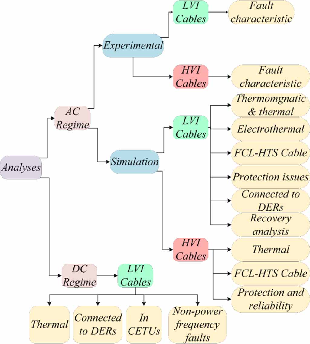
An overview of different types of studies on the HTS cables is illustrated in figure 13. According to this figure, this paper has firstly classified papers based on their operational regime. Afterwards, in each regime, papers are sub-classified based on their modelling/simulation and experimental approaches. However, fault analysis of DC cables is just reported based on modelling/simulation approaches in the literature. Then, papers are categorized based on the insulation thickness of the cables. It should be also mentioned that regardless of the insulation thickness of the cables and their operational regimes, their studies can be classified into many subclasses, such as fault characteristics, thermal transient analysis, FCL-HTS cables, protection issues, recovery time, and application of distributed energy resources.

Figure 13. Different accomplished investigations in fault analysis of HTS cables.
Download figure:
Standard image High-resolution image5.1. AC regime
5.1.1. Experimental approach efforts on low volume insulation HTS cables.
Protection of HTS cables against massive fault currents is one debate with several solutions. One of these solutions is the parallelization of a normal XLPE cable with the HTS cable. Under such arrangement and after the occurrence of a short circuit fault, the majority of the fault current passes through XLPE cable. It is because the drastic impedance increase of the HTS cable during fault which makes it comparable with XLPE cable [146]. Figure 14 displays the results of such an experimental test in [146]. The HTS cable of this experiment was a 22 kV and 2 m long cable made out of 2G-YBCO tapes and XLPE cable had a 250 mm2 cross-section. About 19% of the 25 kA/2 s fault current passes through the HTS cable. This current also passes through the former layer and imposes a massive heat load on the cooling system of the cable. This temperature rise could be analysed and compared with the scenario in which there is no XLPE cable. By having an XLPE cable in parallel to the HTS cable, the weight and the size of the powertrain system will significantly increase which is not desirable. In addition, using a parallel XLPE cable with an HTS cable will increase the cost of the whole system, and will add up to its complexity.

Figure 14. Fault current distribution achieved by paralleling an XLPE cable with a 20 kV HTS cable [146].
Download figure:
Standard image High-resolution imageCurrent distributions of a 0.775 kA cable during a fault are depicted in figure 15. During this fault, about 70% of the fault current passes through the former layer [147]. However, for better protection of the HTS tapes, it should be designed in such a way that more than 95% of fault current passes through the former layer during the fault period.

Figure 15. Current distribution in transient state of 0.775 kA HTS cable [147].
Download figure:
Standard image High-resolution imageWhen fault current passes through the cable, according to Lorentz law, a huge electromagnetic force is applied to superconducting tapes, before they quench. If this force exceeds the mechanical allowances of tapes such as maximum bending and stress of tapes, it could cause the HTS tapes to experience the mechanical collapse [148]. Figure 16 presents induced electromagnetic force on 2G-GdBCO tapes of a CD 66 kV/1.3 kA HTS cable during a 31.5 kA short circuit, which lasts for 2 s [148]. Estimating or calculating the induced electromechanical force is a complicated task during the design stage. However, the maximum possible value of such force must be doubtlessly considered to increase the reliability and stability of cable during operation and also reduce the risk of thermomechanical collapses in HTS cable. Perhaps, an exact formulation to address all variables affecting the total induced force for HTS cable needs to be derived for each cable configuration in the future.

Figure 16. Resulted Lorentz force on 66 kV under fault [148].
Download figure:
Standard image High-resolution imageIn [149] a study was conducted on 22 kV, 66 kV, and 275 kV/12 kA, 2 kA, and 3 kA superconducting cables to investigate their stability and reliability under different circumstances. Three types of failures are imposed to the cables, namely ground fault, short circuit, and broken cryostat. Under a short circuit current, cryostats cracks, and then, the thermal stability of the cable is no more accessible. Under such faults, the reliability and stability of HTS cables are tested and arc voltage and energy were measured. The breakdown voltage for a PPLP immersed in Liquid Nitrogen (LN2) was also measured to be 150–200 V cm−1 for a ground fault with a 1.5 kA fault current. At last, the arc energy of such ground fault was measured as 300–450 kJ.
5.1.2. Experimental approach efforts on HVIHTSCs.
In [150] a protection approach is employed for a 275 kV/3 kA HTS cable against a simulated ground fault. This approach is based on adding a protective layer composed of a multi-layer insulation, which suppresses the heat transfer from superconducting layers to the cryostat pipes. To test the stability and the reliability of the restructured cable during transients, it undergoes some artificial ground faults. The cable was tested under two faults with 10 and 20 kA fault currents. The first fault has generated a 300 kJ arc energy and this value for the second fault was 800 kJ. As a result of applying these faults, the inner core was burned out while the cryostat pipe was remained undamaged. This has proven the proper operation of the added protective layers. However, it has been not mentioned how the weight, size, and cost of the cable change when this method for cryostat protection was applied.
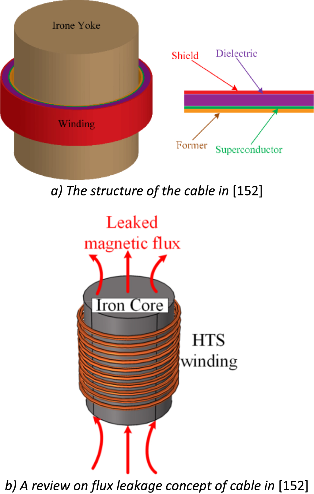
A superconducting cable with limiting properties form a new type of cable, known as FCL-HTS cables which are categorized in many subclasses [151]. One of these types of FCL-HTS cables are inductive-based ones, as shown in figure 17(a). In an inductive FCL-HTS cable, by the occurrence of the fault, current and therefore inductance changes, and as a result, the change of flux linkage causes fault current limitation, as shown in figure 17(b). The more inductive the cable becomes; the limitation level of the cable would be increased. So, iron yokes can be implemented into theses cables to increase the inductance. By applying this method to a 154 kV/600 MVA power HTS cable, the level of fault current limit is increased. The level of fault current is about 2 kA, when an FCL-HTS cable is used without any iron core, 89.25% of the fault current is reduced while this value for FCL-HTS cable with iron core is 93.55% [152]. Though this trend of fault current reduction can be expected in other projects while the numbers may not be the same. The values of the inductances are shown in figure 18, however, there was no discussion in [152] about the weight and size of the cable as important factors, when iron-yoke is applied. Certainly, adding an iron part to the structure of inductive FCL-HTS cable makes it heavy for aviation applications where size and weight are crucial factors, but it will be a good option for terrestrial applications.

Figure 17. Inductive type of superconducting cables for the sake of limiting the fault current [152].
Download figure:
Standard image High-resolution image
Figure 18. The total impedance of the circuit of an inductive 154 kV/600 MVA HTS-FCL cable [152].
Download figure:
Standard image High-resolution image5.1.3. Simulation approach based on low volume insulation HTS cables.
The electrothermal characteristic of HTS cable can be modelled using MATLAB. This means that the temperature, resistance, current distribution, and even the index value can be calculated in each time step and inserted into the ECM or FDM for the next step.
The results can be compared with results of FEM-based software, COMSOL. A Comparison between results of COMSOL and MATLAB of such research on a 10 kV/2 kA made of YBCO tapes and under 5.78 kA fault [139] is depicted in figure 19. As shown in figure 19, the resulting values of MATLAB modelling and FEM are in a good agreement to each other. This study shows that ECMs can be used to characterise the HTS cables under thermal considerations in transient and steady-state regimes [139]. It should be mentioned that in the ECM only radial heat transfer is considered to model the heat conduction of the cable.

Figure 19. Resulted temperature in COMSOL and MATLAB for a 10 kV/2 kA and under 5.78 kA fault [139].
Download figure:
Standard image High-resolution imageIn [153], an analytical model was presented for 66 kV/6 kA/ 5 km superconducting power cable, which fully describes the steady and fault conditions of the understudied HTS cable. The presented formulations in [153] have the advantage of simplicity in applying. This is due to converting the partial differential equation of heat transfer to an ordinary differential equation (ODE). In addition, the effect of former thickness on the temperature variation was investigated. Figure 20 displays the temperature rise of the HTS cable with respect to different former thicknesses for a fault with a duration of 2 s [153]. During a fault, the temperature of the tapes in each phase rises and exceeds the critical temperature value of the cable. Thus, the thicker the stabiliser gets, thermal mass increases and the temperature rise would be lower. However, if the former becomes so thick, then the weight of the cable increases. It should be mentioned that in this reference, the convective heat transfer is neglected due to the short time of the fault and as a result of this the temperature is increase in a completely adiabatic environment.

Figure 20. Temperature rise with respect to former thickness [153].
Download figure:
Standard image High-resolution imageMany research works and papers were and are dealing with the evaluation of the temperature rise in HTS cables during faults. However, a few are dedicated to the recovery of the HTS cables. In [154] a one-dimensional heat transfer along with computational fluid dynamics (CFD) analysis is carried out on a 66 kV CD HTS cable experiencing a 31 kA fault current for 2 s. Results show that different phases have different recovery times which is due to different fault current amplitudes and the material in each phase. Figure 21 shows the recovery times of the HTS cable with respect to the thickness of the PPLP dielectric layer. As a matter of fact, the thickness increase of the dielectric layer reduces the rate of temperature rise in the cable, during fault and, it also increases the recovery time of the cable. This is due to the reverse relation between the radial convective heat transfer coefficient of the cable and the thickness of the PPLP. This means that along with an increase in the thickness of the dielectric layer, fewer heat transfers toward the cooling fluid happens and as a result, recovery time increases. So, utilizing a thin dielectric leads to a longer recovery time of HTS tapes.

Figure 21. Recovery time analysis of a 66 kV cold dielectric cable HTS cable experiencing a 31 kA fault current for 2 s while the thickness of insulation layer in cable varied [154].
Download figure:
Standard image High-resolution imageThis can be also addressed by means of an optimization problem that aims to find the thickest dielectric with the lowest recovery time [4]. The constraints of this optimization problem could be maximizing breakdown voltage, minimizing cost, weight, etc.
To limit the fault current, one way is to reduce the thickness of the former layer. This increases the fault current limitation capability of the HTS cable [155]. By doing this, the resistance of the former increases and this leads to a more effective fault current limitation capability. All of these methods were studied in [154] using an electrical model coupled with thermal model based on FEMs to study transients of a 10 kV/1.75 kA/2.6 km HTS cable under 10 kA fault current. Table 2 lists the limited fault currents by the presented cable for three different case studies [156].
Table 2. Limited fault current for different phases under three case studies, case 1 is an HTS cable with 75 µm stabiliser, the second case is the previous cable with 100 µm stabiliser, and the third one is SFCL + HTS cable [156].
| Phase | Fault Current (kA) | Limited Current (kA) | ||
|---|---|---|---|---|
| Case 1 | Case 2 | Case 3 | ||
| A | 50.0 | 7.1 | 8.6 | 3.7 |
| B | 43.3 | 9.0 | 11.0 | 3.7 |
| C | 42.1 | 10.7 | 13.0 | 3.7 |
The effect of using an FCL-HTS cable under faulty and steady-state conditions on the power quality of the power system was investigated in [157]. It shows that the utilization of FCL-HTS cables could be very helpful to suppress short circuit current in the power network. It worth noting the level of short circuit current is already increased in the power system due to the presence of distributed generations. Therefore, it can be concluded that under the steady-state of the grid, the FCL-HTS cables can operate as inductive power quality correctors, and during fault transients, they can highly reduce the fault current.
To discuss the protection issues of implementing an HTS cable into the grid, a symmetric impedance selection (SIS) is purposed by [62]. In this method, an optimal impedance is selected for the protection system of the HTS cable. This selection is due to the fact that the impedance of the cable varies under faulty conditions and the conventional setting could not satisfy the safe operation of the cable. This study is accomplished on a 22.9 kV HTS cable. Another effort that tends to address the protection challenges is [158]. In this investigation, a novel protection scheme is presented for HTS cables against fault current and quench phenomena. In general, the important finding of this paper is the presentation of a protection setting based on the variation of impedances in different types of HTS cables, conventional and FCL HTS cable. In [159], a novel method is proposed known as Expected Regret-based Impedance Selection (ERIS). This method is used for setting the impedance of the HTS cable during the operation of the protection system. This method applies different uncertainties scenarios to the algorithm to solve the overcurrent relay coordination problem based on regrets of a 22.9 kV FCL-HTS cable. For this purpose, firstly a couple of scenarios are defined based on the status of distributed generators, lines, and FCL-HTS cable. After that load flow and fault current is calculated in presence of FCL-HTS cable. The next level is solving the relay coordination problem based on fault current level and impedance values of the grid, then the values of regret for FCL-TS cable is calculated based on cable impedance and at last the final impedance of the FCL-HTS cable is calculated.
Fault location in HTS cables is another challenging issue related to protection concerns. Many methods based on time-frequency localised phase difference of chirp signal are applied to locate the faulty parts of the HTS cable with the assistance of thermal sensors [160–163]. Another challenge for the application of HTS cables is the lack of a standard fault location method for these cables. To detect short circuits, and find fault location in a 22.9 kV cable, a Stepped Frequency Wave Reflectometry (SFWR) method was applied in [164]. By using this approach, the location of faults in joints, dielectric, and other parts/accessories of the cable was achieved. A South Korean research team has investigated the impact of HTS cable on protection systems in [165]. This study demonstrates that by applying the characteristics of superconducting cable to relays setting, fault detection might be problematic. Two types of relays are studied, current differential relay and distance relay. It is worth noting that, a similar study was done on a 154 kV/600 MVA/1 km HTS cable in [166].
In [167] a study was conducted to investigate the effect of different control and protection strategies of wind turbines (WTs) on a 10 km long 22.9 kV/2.4 kA/60 MVA HTS cable under a 500 ms short circuit with a maximum fault current of 5 kA. In this study, the permanent magnet synchronous generators are used as implemented electrical machines in wind turbines to supply 60 MVA using six 10 MVA turbines. This study indicates that transients of WTs could also lead to quenching phenomena in HTS cables which must be considered before implementing HTS cables in power systems with wind farms.
An ECM was presented for a 1 km length 10 kV/1 kA triaxial MVHTS cable which was exposed to a 15 kA power frequency fault for 140 ms. During a fault, the temperature of phases A, B, and C reaches around 150 K, 127 K, and 107 K, respectively [168]. The aim was to present an ECM can enable the thermal and electrical characterizations of tri-axial superconducting cables, based on their geometry.
In [169], an ECM for a 22.9 kV/1.26 kA/60 MVA cable was implemented in the PSCAD/EMTDC software package. After dealing with the HTS cable modelling process in PSCAD/EMTDC, the transient characteristic of this 1 km length, triaxial HTS cable was analysed under a 15 kA fault which lasts for 82.5 ms. Figure 22 demonstrates the fault current and the resistance, of the HTS cable by the proposed model in PSCAD/EMTDC. The ECM model is also proposed for a co-axial HTS cable operating at 22.9 kV. This model characterises not only the electrothermal coupled with magnetic and mechanical behaviour in transient and steady-state of HTS cable but also considers the impact of grid and fault parameters on cable transient characteristics [57]. Different fault resistances, fault types, and fault duration times are tested in this reference. The drastic increase in fault resistance of the HTS cable compromises its safe operation after fault clearance. This is due to the possibility of the transition of HTS tapes to the flux flow state in high resistance faults. Another finding of [161] is that the asymmetrical faults induce a massive Lorentz force to the HTS tapes.

Figure 22. Results of ECM of a 22.9 kV/1.26 kA/60 MVA under a 15 kA fault, (a) fault current (b) resistance.
Download figure:
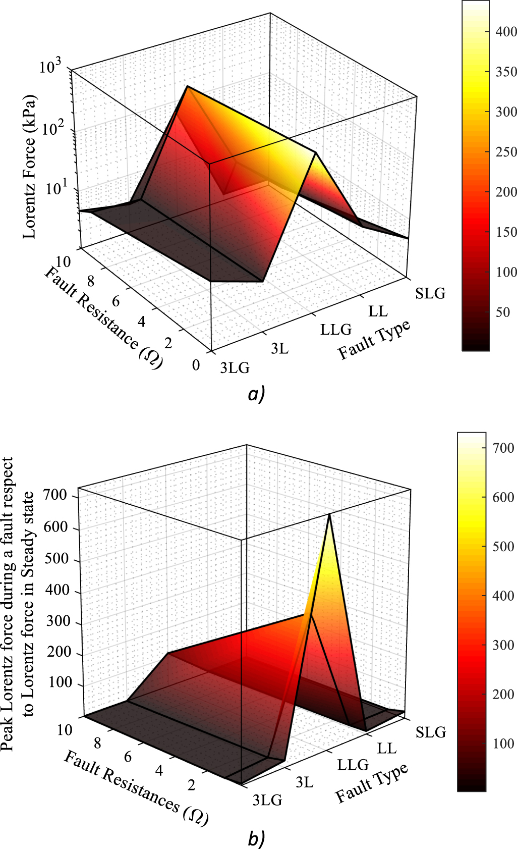
Standard image High-resolution imageFigure 23 presents the imposed Lorentz force due to different fault types in phase-B. However, the impact of non-power frequency faults on the resistivity of the ground and fault current must be also included to increase the accuracy of the model.

Figure 23. Lorentz force of an AC HTS cable under different fault resistance and fault type (a) the value of Lorentz for under different faults (b) the division of the maximum value of Lorentz force under fault conditions and steady state condition.
Download figure:
Standard image High-resolution imageTo reach an accurate model of an HTS cable, a Multiphysics approach is required. In [170, 171], LN2 was modelled using a 1D thermal model while electromagnetic and thermal characteristics of the cable is modelled as a 2D problem, implemented in COMSOL. By doing this, the current distribution, temperature rise, and AC loss during transients as well as recovery time and performance after fault were calculated. During a fault, temperature increases adiabatically, whilst after the fault is cleared, a non-adiabatic environment releases heat to the coolant fluid. This convective heat transfer dissipates the heat to the LN2 and cools down the HTS tapes in cable. Therefore, to reach the highest accuracy possible, an electromagnetic model with thermohydraulic considerations is needed. To solve this, FEM-based modelling approaches are applicable.
5.1.4. Simulation approach based on HVIHTSCs.
Reliability analysis of HTS cables is an interesting topic that facilitates the large-scale employment of HTS cables in cryo-electrified systems. However, HTS cables operate as complex elements from the reliability point of view (because of their complicated structure and different materials and mediums used in these cables) and this complexity hardens the reliability analysis. A method for the reliability assessment of superconducting power cables was introduced in [172]. This paper divided an HTS cable system into three subsystems to simplify the reliability assessment procedure: HTS cable, cryogenic refrigeration system, and termination of the cable. This method is carried out on a 110 kV cable. The results showed that parallelization of a conventional power cable with the superconducting cable could guarantee a high level of reliability increment, however, no economic evaluation was presented or discussed for such a solution.
Terminations and current leads are components of the HTS cables which must be analysed during the fault assessments of HTS cables. The location of the fault and its current amplitude can impact the temperature rise in current leads, and put huge thermal stress on them. To analyse the temperature distribution in a 1 m long current lead, an FEM-based simulation is conducted in [173]. The results are shown in table 3 for different fault current amplitudes and different locations of temperature measurement.
Table 3. Temperature variation of the current lead during multiple types of faults with different current amplitude while the temperature is measured in different points.
| Location of Temperature measurement (mm) | Steady State | Temperature (K) | ||
|---|---|---|---|---|
| Fault Current-10 kA | Fault Current-20 kA | Fault Current-30 kA | ||
| 0 | 77 | 77 | 77 | 77 |
| 10 | 80.473 | 82.592 | 88.629 | 98.317 |
| 20 | 84.005 | 88.024 | 99.513 | 117.65 |
| 30 | 87.583 | 93.001 | 108.26 | 131.76 |
| 40 | 91.194 | 97.442 | 114.69 | 140.74 |
| 50 | 94.827 | 101.44 | 119.44 | 146.35 |
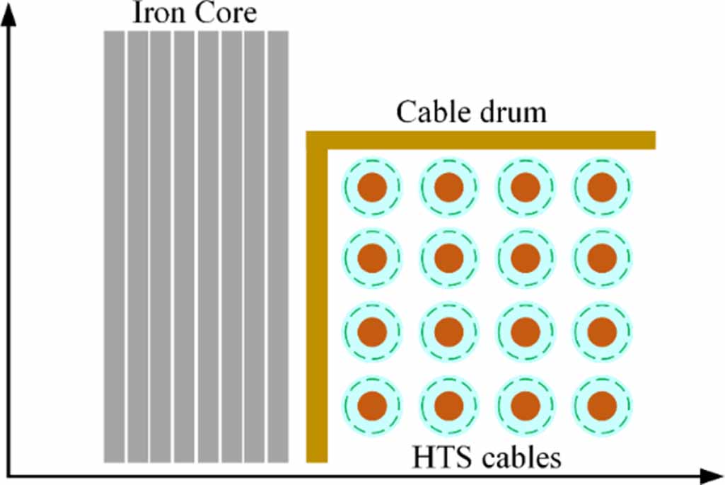
The mathematical model of an inductive type of a 154 kV FCL-HTS cable is presented in [174] which operates in the same way as an inductive SFCL. The fault current limiting capability of this cable was investigated using an analytical formulation for a 63 kA fault current. This cable is depicted in figure 24. The electrothermal characteristic of FCL-HTS cables can be investigated through an electrothermal model which simulates the heat transfer in the HTS cable using. Such a model analyses the impact of temperature changes on the electrical behaviour of a 154 kV/2.25 kA/600 MVA HTS cable under 50 kA fault for 12–60 cycles. For more effective current limitation, multiple former materials and arrangements have been tested in [175], such as stainless steel (SUS), Brass-based and hollow former. Results show that in presence of the SUS former, the fault current is 92.5% reduced while this value for the hollow former is about 50%. However, there was no discussion on whether this new type of former can also satisfy the economic considerations or it is just technically beneficial.

Figure 24. Novel FCL-HTS cable type presented in [174].
Download figure:
Standard image High-resolution image5.2. DC regime
Along with the advancement of technology, the utilization of DC HTS cables is gaining attention, not only as an element for transmission of future power grids [35, 176] but also as a major part of CETUs such as future aircraft [177, 178]. However, DC HTS cables still need to be further investigated to overcome challenges before it takes the lead of power transmission in future grids and cryo-electrifications applications. Transient analysis of DC HTS cables is one of the most crucial aspects of its study. This section is dedicated to reviewing all fault studies in DC HTS cables.
In [176], an investigation is carried out on the magnitude of fault current in a DC grid in presence of five 0.775 kA/ 0.2 kV/0.36 MJ/0.15 MW SMESs and 0.2 kV/100 kA/20 MW HTS cables. The combination of these two elements reduces the fault current amplitude from 42.5 kA to 37.5 kA, while if neither of them is used, fault current amplitude is more than 100 kA.
In [179], an assessment is performed on the thermal behaviour of a 50 kV DC HTS cable. A distinguished aspect of this study is the integration of the finite difference time domian (FDTD) method and volume element method. By applying such methods to heat transfer formulations of HTS cables, the exact temperature change during and after the fault was achieved. The thermal effect of different types of faults, including normal short circuits, energization, and lightning was considered in [175]. Results show that the 1 s short circuit fault increases the temperature of the cable to a maximum value of 120 K while this value for energization abnormality is about 90 K and for lightning is about 72 K while the operational temperature was 70 K.
High voltage direct current (HVDC) systems are one of the most probable systems for applying DC HTS cables. Accordingly, an analysis is accomplished in [180], in which HTS cable is functioning as a major transmission DC line with a length of 300 km and has a self-acting function against faults. This cable is placed in a Line-commutated Current-sourced Converters (LCCs)-HVDC system which is suffering four types of faults, one is DC ground fault; single-phase, and three-phase faults on the load side, and interphase (between layers in cable) fault. The accurate behaviour of the HTS cable during quench was considered. Figure 25 presents the impact of the proposed HTS cable during DC ground fault on the DC side of the grid compared with a conventional counterpart. It shows that regardless of the type of the fault, the proposed cable can reduce fault current in the LCC-HVDC system. For instance, the value of the fault current for a DC ground fault is 20% reduced when using the proposed cable instead of conventional HTS cables.

Figure 25. Effect of DC HTS cable on fault current passing through DC side of grid [180].
Download figure:
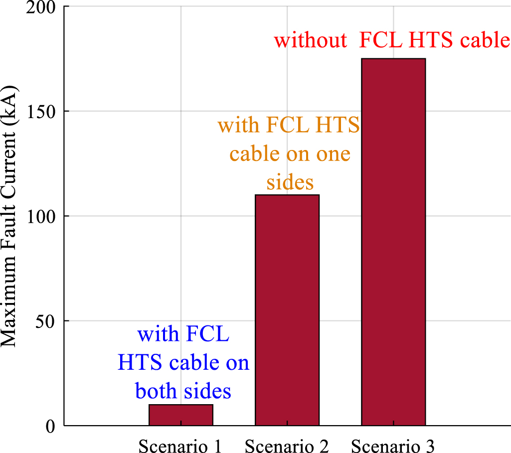
Standard image High-resolution imageAnother utilization of DC HTS cable is in future cryo-electrified airplanes. In an aircraft where safety should be a priority, fault incidents in absence of a proper fault management system could lead to a catastrophic disaster that threatens the lives of passengers. In order to prevent such tragedy, a highly reliable fault limiting and management system is required. In [181], two methods were proposed to limit fault current in an airplane. The first method is to use a 4 kV/2 kA SFCL while the second one uses an FCL-HTS cable. Simulation results illustrated that FCL-HTS DC cable is more effective in fault current limitation, i.e. it can reduce fault current from 175 kA for the line to line short circuit to 11.4 kA when is used on both generator and motor sides. Figure 26 shows the impact of FCL-HTS cable on fault current in an airplane. This figure shows again the significant impact of the FCL-HTS cables on the value of fault current. A similar study is investigated for electric ship propulsion systems in [182].

Figure 26. FCL-HTS cable effect on fault current in an airplane [181].
Download figure:
Standard image High-resolution imageA brand new study was conducted in [183] to attain the important factors affecting the electrothermal stability of a single layer DC HTS cable with a 920 A critical current. The cable consists of a stainless steel-based former, inner and outer insulations (PPLP), 2G superconducting tapes, and PI films semiconductor layer. A DC impulse fault current passes through the HTS cable with amplitudes of 5 kA, 5.5 kA, and 6 kA while the duration of the fault currents varied from 100 to 150 ms. The main parameters which are studied in this paper are maximum resistance, generated heat, and recovery time which are reported in table 4.
Table 4. The fault performance of the DC HTS cable in [183] under different fault scenarios.
| Fault current (kA) | Fault duration (ms) | Maximum resistivity of superconducting layer (
| Recovery time (s) | Generated heat (kJ m−1) |
|---|---|---|---|---|
| 5 | 100 | 0.21 | 0.26 | 5.5 |
| 5 | 150 | 0.89 | 2 | 13 |
| 5.5 | 100 | 0.45 | 0.6 | 7 |
| 6 | 100 | 0.43 | 0.8 | 7 |
6. Future trends
6.1. For cooling units against faults
During the steady-state of the power grid, cooling systems must stabilise the temperature. In faulty conditions, they must suppress the rapidly increasing temperature by providing an effective removal of heat in order to reduce the recovery time. This can be carried out by the application of new cryogenic fluids, such as liquid hydrogen (LH2), liquefied natural gas (LNG), liquid argon (LAr), liquid neon (LNe), liquid oxygen (LO2), and liquid helium (LHe). These cryogenic coolants have different specific heat capacities, thermal conductivities, and densities. According to the convective/conductive heat transfer equation, this causes different fault performances for HTS cables. However, choosing the coolant actually depends on the application, for instance, for HTS cables in terrestrial power systems, the most available and cheapest option is still LN2, whilst LH2 is promising to be used in future for electric aircraft, and other CETUs. Table 5 lists the most important parameters of the discussed cryogenic coolants. It must be however taken into account that decreasing the coolant temperature leads to an increase of the critical current. The higher the critical current gets, the higher is the heat generated in fault conditions.
Table 5. Properties of cryogenic coolants [184].
| Coolant | LH2 | LAr | LNe | LO2 | LHe |
|---|---|---|---|---|---|
| Normal boiling point (K) | 20.28 | 87.3 | 27.1 | 90.2 | 4.22 |
| Thermal conductivity (mW mK−1) | 98.4 | 128 | 113 | 152 | 18.7 |
| Specific heat capacity (J (kg K) −1) | 20.35 | 87.3 | 21.7 | 90.19 | 4.22 |
| Liquid density (kg m−3) | 70.85 | 1393 | 1205 | 1141 | 125 |
Cryocoolers are essential components of the cooling system that enable the pre-cooling and re-cooling of the warmed fluid. The most common type of cryocoolers which are used for cooling down the HTS cables is the Gifford McMahon and Stirling types [20, 185]. However, these types have low reliability, low cooling power/capability, and so cannot be used for long HTS cables [186, 187]. As a result of this, a new type of cryocoolers, known as turbo Brayton cryocoolers, has been proposed for long HTS cables which are going to be implemented in aircraft, ship, and spacecraft [188–190]. The integration of such cryocoolers contributes to the increase in total efficiency of the HTS cables, more stable temperature, lower weight, lower cooling cost, and longer length with higher voltage HTS cables would be achieved [191]. As mentioned before, cryocoolers are used to maintain the temperature of the fluids at the base operating temperature. The type of cooling system and its components must be designed so that they can dissipate the massive energy released during a fault effectively as superconductor quenches. Joule loss in cable would be also quite significant compared with normal operation. Therefore, cryocoolers and their parameters must be selected appropriately. However, right now and due to low reliability, efficiency, and massive weight, cryocoolers have an aura of ambiguity to be used massively in sensitive applications, such as aircraft.
6.2. Fault-tolerant current limiting (FTCL) HTS cables
FTCL HTS cables are types of HTS cables which not only suppress the short circuit currents during fault period but also tolerate the fault current for some cycles without any damage to their structure, especially HTS tapes. It may raise the question that why one has to use these cables instead of SFCLs. To answer this question, consider a stand-alone power system of an aircraft. Usually, the body of the electric aircraft are built by some high resistive materials such as carbon fibres which increase the possibility of high impedance faults (HIFs). In this type of faults, the rate of fault current increase is not as high as low impedance faults and this can lead to malfunction or failures of protection systems. Also, due to current-dependant characteristic of SFCLs, they are not able to react very well against HIFs. This is where FTCL-HTS cables show their effectiveness and by using these cables, the HIFs would be tolerated for several seconds and the power also would be delivered without being interrupted. There are also some technical reasons to use them in electric aircraft, as shown in figure 27, there are multiple options to distribute the generated power in electrical aircraft to the loads and propulsion units. The first is using a normal cable in series with an SFCL to distribute the electrical power. Due to the presence of the conventional cable, this grid is the heaviest option among others, with the highest level of power loss and lower efficiency. Using an HTS cable could reduce the weight and increase efficiency and reliability, however normal HTS cables are very sensitive against faults. Thus, using FTCL-HTS cables is an appropriate option in electric aircraft to increase the efficiency and safety of the distribution system.

Figure 27. Different topologies for a more electric aircraft and the impact of the presence of FCL-HTS.
Download figure:
Standard image High-resolution image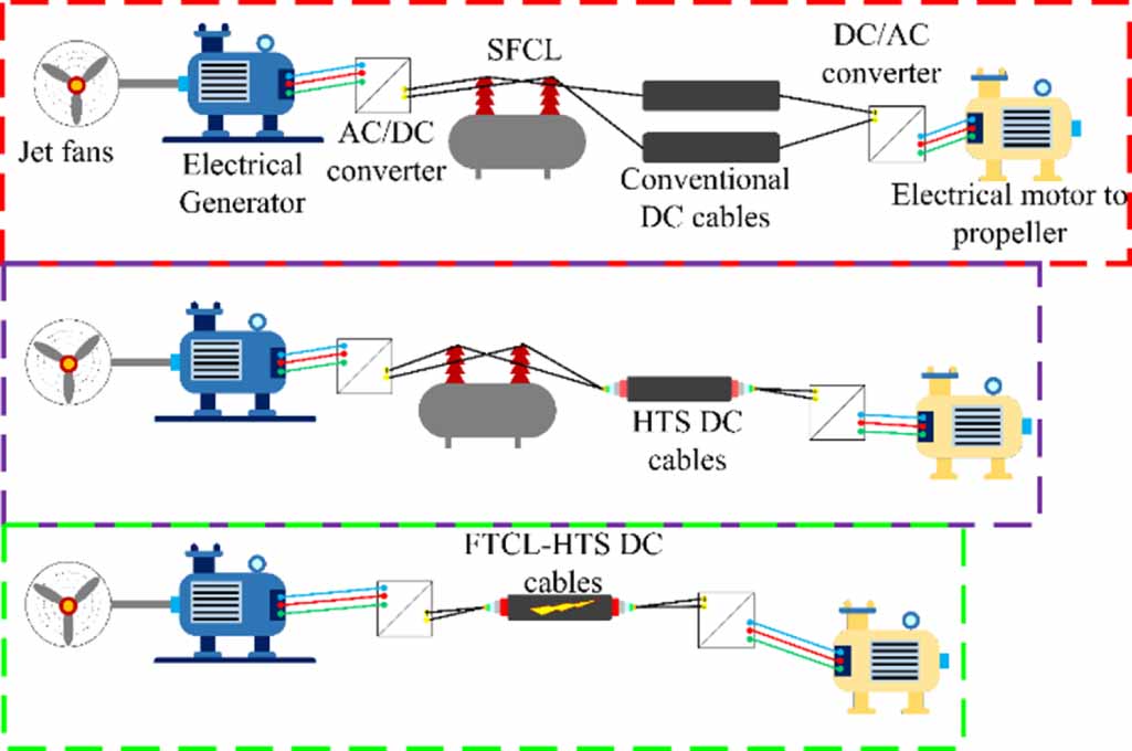
It must be noted that modelling and simulation of HTS cables, regardless of the type of study, are an important step during the design process and before applying them in power grids or in CETUs. Simulations can be accomplished by different software. MATLAB/SIMULINK is usually used for ECM and FDM approaches while the cable is operating in steady-state or under transient regimes. EMTP and PSCAD are used for transient analysis of the cable when a non-power frequency fault is applied, namely fast transients, very fast transient, and ultra-fast transients. COMSOL and ANSYS both use FEM to model the thermal, magnetic, or mechanical behaviour of the cables whilst GASPAK is an FDTD-based software mostly used to model the thermohydraulic behaviour of HTS cables.
6.3. New standards for testing and fault performance of HTS cables
Faults can be caused by three major reasons including natural causes, errors, and attacks. The first group is related to the faults caused by hurricanes, storms, floods, solar flares, and earthquakes. Malfunction of the devices and human mistakes are originated from the second fault subclass. At last, the third group of faults in power systems could be caused by cyber and human attacks [192]. To face each one of these events and for each conventional component of the power system, there are standards in IEEE, IET and CIGRE [193] published to increase the reliability, resiliency, stability, protection level, and availability of the power system. However, there is a lack of such standards for grids with HTS cables and there is a need to establish a standard.
6.3.1. Design standards considering faults for a normal, FCL, and FTCL-HTS cable.
Fault performance of HTS cables needs to be considered during the design stage, especially when the cable is designed for sensitive applications such as HVDC systems, wind farms, and CETUs. The cable must be designed so that the fault current has the minimum impact on the proper function of the cable during and after fault, i.e. HTS tapes must be protected (electrically, thermally, and mechanically) during fault and should be recovered to a superconducting state at fastest possible rate. Formers should be designed so that impose the lowest possible heat load to the cooling system of the HTS cable while the maximum fault current passes through and the shield layer should be designed for providing a return path for fault current without any damages to the main conductors. Dielectric of HTS tapes (if tapes are covered with them) and also of phases have a vital role in faulty conditions. They must provide a high heat transfer ratio to prevent heat accumulation.
6.3.2. Standards for short circuit fault tests of the HTS cables: electrical/thermal/mechanical and configuration considerations
Standards are also needed regarding tests of HTS cables. At the moment, none of the well-known workgroups (IEEE, CIGRE, etc) presents standards on how to conduct short circuit testing for HTS cables.
In any future testing standards, some factors and parameters must be defined such as:
- (a)The level of fault current (compared to nominal current) which testing should be done for each type, and power level of HTS cable,
- (b)Fault current duration,
- (c)The number of times that a standard fault needs to be applied to the cable to ensure its performance under fault condition,
- (d)Maximum allowable temperature increase for a specific fault
- (e)Mechanical requirement for reinforcing an HTS cable in installation bed considering dynamic forces during a specific fault
- (f)A full testing procedure for applying such testing standards.
These testing standards must consider the type of tapes, structure of the cable, its specific applications, and fault current capability of the cable. That means that standards for a triaxial CD conventional HTS cable with 2G HTS tapes should be fairly different from standards for a CORC cable, however, general considetion for testing them can be still the same.
6.3.3. A standard for accelerated aging tests and maximum permissible temperature of different dielectric, and thermal insulation in HTS cables.
Dielectrics, thermal insulations, and cryogenic fluids need a specific type standard for HTS cable and against faults. In such a standard maximum permissible temperature rise for an HTS cable with a specified current level should be explained when it is tested under a specific fault with known fault duration. It is worth noting the quality of performance and lifetime of dielectrics, thermal insulations, and the cryogenic coolant change if their temperature changes drastically. In addition, the temperature increase of insulation layers can drastically reduce the lifetime of electrical devices. This is highly important for the correct operation of the HTS cable after the fault clearance. This is to ensure that if the HTS tapes recovered successfully to a superconducting state after a short circuit fault, the aforementioned elements are capable of performing up to the standard. Thus, a standard must be established to guarantee and predict the quality of the dielectrics and thermal insulations after fault clearance especially for cables used in CETUs. In addition, accelerated aging tests, and fatigue tests caused by fault current need to be standardised for the insulations and dielectrics which are used in cryogenic temperature.
6.4. Faster modelling approaches based on data-driven methods using AI
Superconducting cables can be simulated by many numerical methods. FEMs have high accuracy and very low simulation speed, i.e. high computation cost while ECMs have acceptable simulation time and accuracy. However, the efficiency of ECMs must be further investigated to become mature enough for industrial use. These modelling methods are known as white-box models. To have higher accuracy and lower computation time, AI techniques can be used to create black-box models (BBMs) [124, 194–198]. At the first step, these models are trained with the help of experimental and simulation input data. Afterwards, the model is ready to give outputs for any kind of inputs in the test phase. BBM models are used for the sake of the AC loss prediction in [58]. BBMs can be used to predict the maximum temperature of superconducting tape and coolant, the maximum applied force, the possibility of tape burnout, and many other factors during the transient analysis of HTS cables. BBMs can be also used to create a fast and accurate model for system level modelling of grids in which HTS cables are implemented. For instance, when one HTS cable is implemented in a power system of an aircraft, the system fault analysis can be conducted faster with BBMs. On the other hand, AI-based models are also capable of being used in condition monitoring, fault detection, fault location, protection system coordination, and many other faults related applications, in a real-time manner.
Last recently, edge computing, 5G data-transfer concept, internet of things, and cyber-physical systems have led to a whole new concept, known as digital twins (DTs). The DT is defined as 'a virtual domain that is used as a real-time digital counterpart of a physical object or process' [199]. DTs have potential to be used in many important industries, such as power systems, smart cities, aviation, marine, healthcare, etc [200]. For studying fault performance of HTS cables, DTs could be used to address some challenges and issues. As discussed before, when HTS cables suffer a short circuit fault, their impedance rapidly increases and this complicates the decision-making process of the conventional protection systems. Here DTs could be applied as a condition monitoring tool that could help the protection systems to digest different types of faults, transients, and other abnormalities and making the right choice in a real-time manner. On the other hand, DTs can be used to monitor the health condition of HTS cables, during and post faults to predict the remaining life of their dielectrics, to analyse any internal defects, failures, and malfunctions in components of the HTS cables after recovery from a severe fault. Also, DTs can be used to optimize the structure and design of the HTS cables with respect to all available trade-offs, constrains, and requirements of a specific application. This is the case when HTS cables are massively commercialized and manufactured. For instance, when one designs an HTS cable for aircraft application, weight, loss, size, and cost must be minimised with respect to the operating condition of aircraft power system while it is possible that many other limitations and trade-offs occur during the flight. Flight operating conditions would be needed to monitor the performance of HTS cable in normal and faulty states. The information learn from each flight would be fed into a DT model to feedback the manufacturer to improve the design of HTS cables based on real conditions of flight.
6.5. Faults in superconducting cables of cryo-electrified transportation applications
One of the most promising applications of superconducting cables is in future modern transportation applications such as electric aircraft, ships, and spacecraft. There are some transient-based considerations to make before using these cables in the aforementioned applications.
In naval applications, the load is not cyclic and a fast change is highly possible. This may result in temperature increase and inability of HTS cables to supply the demanded load. FCL-HTS cables and FTCL-HTS cables can be used as variants for normal HTS cables to address this issue. There is another consideration for HTS cables of marine application. In this application, the cables are longer than those used in bulk power systems. This is due to the fact that the bulk system has a point-to-point nature which is not the case in marine power grids. As a result of this, the number of joints increases and this could cause problems in fault detection systems for HTS cables [201]. The electrical system of electric ships is based on bi-polar or mono-polar DC grids. In these grids, two types of faults are very common, pole to ground faults and pole to pole to ground faults. These faults inject a massive amount of energy which not only deteriorates the HTS tapes but also could lead to failures in cryogenic systems and cause dielectrics and insulations failure. To avoid this, increasing the mass density of the gaseous insulations can be helpful. Also, the temperature gradient inside and outside the cryostat must be minimised. If this temperature gradient increases, the mass density of the gaseous insulation is reduced and this results in losing the dielectric properties. This is a higher-level consideration for the case of the pole to pole to ground faults in which the released energy is the highest. The injected energy reduces the value of the critical current [131].
The HTS cables with respect to their specific fault characteristic can impact the fault management strategies of aircraft. Thus, if they are implemented in such systems, these strategies must be reconsidered so that the faulty part is isolated so fast that the HTS cable does not quench [202]. One last concern about transients in electrical aircraft occurs during the switching time. This type transient injects a high current or/and an overvoltage to the system which could jeopardise the safe operation of HTS cables [203]. At last it should be noted that Hydrogen-based airplanes are promising to be part of the future of electric aviation. So, any utilization of HTS cables in these aircraft, must be conducted with respect to the cryogenic properties of LH2. This can impact the fault current amplitude, safety margin, and even type of utilised tape [204].
6.6. Application of superconducting cables in future modern and restructured power systems
The structure of the power systems is changing to be more distributed. As a consequence of this, the distance between generation units and the loads is dramatically reduced. This provides a great opportunity for HTS cables to play their part. However, there are considerations to make.
6.6.1. Applications of HTS cables for transmitting power generated in the off-shore wind farms.
The recent integration of wind farms in power systems, especially the off-shore types, has drawn huge attention. This is due to their lower cost of power generation (compared to some other renewable approaches) and being environmentally friendly. In the future, generated power of an off-shore wind turbine would be higher than 20 MVA. These farms are usually located far from the shores in the seas. This makes conventional cable lines and overhead lines abolished options to transmit the generated power of wind farms to load centres. To deal with this challenge, superconducting cables are proposed as transmission lines with the lowest possible loss and high current capabilities at a lower voltage [167, 205]. However, because of the underwater location of these cables, their long length, and quench phenomenon in these cables, fault detection and location in them is not possible to be accomplished by conventional methods. So, there is a need for novel method for fault detection and location. On the other hand, relay operational settings must be reconsidered to overcome the challenge of the variable impedance of the HTS cables before and after a fault. Dealing with these difficulties could be conducted through implementing novel intelligence protection methods, based on AI. The islanding operation mode of the power systems supplied by off-shore wind farms is another futuristic consideration for such grid with HTS cables. Islanding operation mode injects a massive fault current which HTS cables must be designed for so that this fault current cannot deteriorate its structure. These cables are better to be designed as FCL-HTS cables or even FTCL-HTS cables to ensure that the supplied power by the wind farms would not be interrupted at all.
6.6.2. The application of HVDC-HTS cables for creating energy hubs and their new fault scenarios.
In some countries, there is a long distance between generation units and load centres, maybe more than hundreds of kilometres. On the other hand, sometimes the generation of electricity in a location is much cheaper than in other locations, therefore, the idea of energy hubs has been developed. To supply these loads under such long distances, conventional overhead lines and cables generate a massive loss which increases the cost of operation in power systems. To address this issue, HVDC systems were proposed as a solution. However, they still face a high level of power loss in ultra-long systems. Once again, superconducting cables could be used to further reduce the loss in the power system. Among HTS cables, DC HTS cables are more promising options due to their lower loss in comparison to AC HTS cables and the requirement for fewer cooling/pumping stations which is due to their lower heat load. However, for such a long DC HTS cable line, some issues must be addressed before its integration in a power system. They originate in the high number of joints in long HTS cables which results in failures and errors in fault location and detection procedure. In addition, joints get very hot during the course of a fault, which imposes a massive heat load on the cooling system. There is also a need for changes in the fault management strategies of relay protection systems. This means that relays action considerations, protection zones, and even protection coordination must be reconsidered and recalculated based on fault performance of HTS cables.
6.6.3. Possibility of application of HTS cables in microgrid.
When off-shore wind turbines or coastal micro-grids are used, there is a high potential for using clean/green hydrogen as coolant fluid for HTS cables. By employing such a fluid, substantial changes on fault tolerability and properties of the cable take place. There is also a great opportunity for implementing the AC MgB2 cables in such grids due to the fact that their satisfactory performance in temperatures near 20 K, the boiling temperature of LH2 [206, 207].
Taking the advantages of DC power systems is a growing trend, especially, in last few years and many devices, resources, and applications were developed that operate in DC regime. In generation side of the power systems, solar photovoltaic power plants are the most recognized DC energy resources while for storage systems of any smart/micro grid, batteries are other DC devices. These DC systems could be used to supply the power of multiple new applications such as data centres, metal smelting factories, electric vehicle (EV) charging stations, and DC buildings [208, 209]. Recently, the opportunity of using DC HTS cables in such low voltage DC (LVDC) applications were discussed. Under such circumstances, a lower heat load is imposed to the cooling system and this increases the efficiency and reliability of the cooling system while the temperature becomes more stable. Another potential application of DC HTS cable is in data centres that play a critical role toward the full digitalization of power systems [210]. These centres require DC power to run their internal devices such as routers, switches, computers, etc. Thus, by using LVDC HTS cables the AC loss, heat load, required cooling power, operation cost, and total ownership cost of these centres are reduced significantly [211]. Another potential application is using DC HTS cables and HTS busbars in smelting factories that require a massive current around 10 kA to 100 kA to operate. DC HTS cables and busbars are economic solutions with lowest possible loss while other counterparts such as highly pure copper busbars or aluminium busbars operating at low temperature have a much higher loss in comparison to DC HTS cables. Also, along with digitalization of power systems, smart buildings, DC buildings, and EVs are integrating more and more in the next generation of power grid and electrical devices. Using DC HTS cables for these buildings and EV charging stations are expected in coming years.
As discussed previously, the DC HTS cables are key components of future LVDC power systems that supply the power from generation and storage units toward the loads. Although, some investigations were conducted on the application of DC HTS cables in LVDC grids, their electro-magneto-thermal performance under short circuit faults must be studied. On the other hand, DC HTS cables are the main bridge between the energy hub and the loads and any failure and fault in these cables could interrupt the appropriate function of the loads.
6.7. Fault performance of novel types of cables
New types of HTS cables were proposed, based on changes in their magnetic, mechanical, and thermal structures.
6.7.1. MgB2 cables and their fault performances.
Hydrogen as coolant medium is very attracting for future production and use in power systems, as green hydrogen can be produced using the electrolysis of water using green energy produced in wind farms. The boiling temperature of the LH2 is near 20 K which enables its use in MgB2-based cables. At this temperature, MgB2 cables have low AC loss, and very low cost compared with other types of superconducting cables [212, 213]. In addition, as MgB2 wire has a round shape, it can be easily accommodated into a former made out of Titanium or other suitable materials to form a cable. Likewise, their fault performance must be considered. The first consideration is the highest tolerable before burn out. Second one is related to the mechanical performance against massive fault current. In fact, the question is how much force they can tolerate before experiencing mechanical collapse. Furthermore, there is a need for considering the changes in fault location and fault detection algorithms and adjust them with the thermomagnetic characteristic of these cables.
There is a lack of an extended analysis on the fault performance and characteristic of the MgB2 cables under short circuits. The first issue is related to the behaviour of dielectrics at 20 K temperature. It must be specified how much heat can be transferred through these dielectrics in such a low temperature. Also, there is no evidence on that if the conventional design procedure which used for YBCO and bismuth strontium calcium copper oxide (BSCCO)-based cables to handle faults is applicable for MgB2 cables. In addition, cost/economic and technical studies need to be done to find the best superconducting material for a cable in a specific application, as for example, considerations for terrestrial and aerospace applications are quite different.
6.7.2. CORC cables fault performances and their application in CETUs.
Recently CORC cables were proposed for being used in many applications such as magnets and transformers. They are a possible solution to be applied in stand-alone power grids, such as in aircraft and ship. This is not only due to their performance in steady state but also is due to their fault current limiting capabilities. Recently, numerous studies were investigated to show their performance in aircraft under faults and transient [63, 214]. It should be highlighted however that the fault location and detection algorithm must be adjusted with respect to their specific structures.
6.7.3. Hybrid energy lines (HELs) and the fault behaviour of the HTS tapes in LNG cryogenic environment.
During the last decade, a novel type of energy line was proposed to simultaneously transmit the electrical power and LNG, known as HELs. In such energy lines, a superconducting cable is implemented into a pipeline that transmits the LNG/LH2. These lines can provide a large energy transmission capacity, low AC loss, and long-distance transmission system while LNG/LH2 can provide an excellent cryogenic environment which leads to enhancement of critical current [207, 215]. Their design, cooling considerations, thermal insulations, and dielectrics are discussed in details in [216, 217].
Fault performance of HELs is highly important due to the fact that any failures in these energy lines could have collateral damages not only on the energy market economic concerns but also increase the safety risk regarding explosions of LNG/LH2. Therefore, they must have high reliability against short circuit faults and any other type of fault. The condition monitoring system of HELs needs novel methods due to their long length and different structure. Generally, faults can be categorised into three classes. The first one is related to faults and failures in LNG transmission systems, such as corrosion of their pipes and their cathodic protection. These types of faults could lead to malfunction of the cooling system which results in a quench of electrical parts. The second type is related to electrical faults in the superconducting part of the HEL. This not only causes damages to electrical parts but also could jeopardise the correct operation of LNG-related units. At last, there is a third type that engages electrical and LNG systems at the same time. This could be due to malfunctions in the cooling system. As a consequence of this, fault management strategies need to be more specific and must be capable of differing each type of these faults and making the right choices to increase the reliability and availability of the energy [218, 219].
7. Conclusion
The fault characteristic of high temperature suerconducting (HTS) cables is an important issue especially in future cryo-electric transportaion systems, HVDC grids, and wind applications. This is due to their different thermo-hydraulic and magnetomechanic characteristics during faults, in comparison to conventional cables and trasnmission lines. Thus, this paper has provided a topical review on all conducted and related studies on the fault and transient behaviours of HTS cables. Most important efforts of this paper are as follow:
- A brief introduction on superconductors and HTS cables were provided
- The structure, toplogy, and cooling designs of HTS cables were discussed and their impact on fault behaviour of HTS cables are assesst
- The challenges that HTS cables can face during fault periods, were expressed in detail.
- All related papers which have worked on fault performance of HTS cables were reviewed extensively, and shortcomings were discussed.
- At last step of the paper, future trends and demands for HTS cables were discussed to make rooms for future studies and investigations.
Acknowledgments
The first author would like to express gratitude to Dr Danko van der Laan (Advanced Conductor Technlogies LLC, USA) for providing the figure 3, i.e. the CORC HTS cable photo.
Data availability statement
All data that support the findings of this study are included within the article (and any supplementary files).