
Abstract
We present a shape memory polymer (SMP) honeycomb with tuneable and shape morphing mechanical characteristics. Kirigami (Origami with cutting allowed) techniques have been used to design and manufacture the honeycomb. The cellular structure described in this work has styrene SMP hinges that create the shape change and the deployment actuation. To create a large volumetric deployment, the Kirigami open honeycomb configuration has been designed by setting an initial three-dimensional re-entrant auxetic (negative Poisson's ratio) configuration, while the final honeycomb shape assume a convex (positive Poisson's ratio) layout. A model was developed to predict the shape change of the structure, and compared to experimental results from a demonstrator honeycomb deployment test.
Export citation and abstract BibTeX RIS

Original content from this work may be used under the terms of the Creative Commons Attribution 3.0 licence. Any further distribution of this work must maintain attribution to the author(s) and the title of the work, journal citation and DOI.
1. Introduction
Origami engineering has been branded as one of the most promising multiscale design methods to produce structures and materials with unusual deformation mechanisms and shape changing characteristics. Origami tessellations have been used to develop deployable structures for space applications [1–3]. Other applications of Origami have ranged for example from corrugated cores [4–6] to stents designs [7], micro-assembly and robotics [8, 9] and graphene technology [10]. All these applications are compounded by the use of several mathematical frameworks that allow to design the engineering applications from first principles [11–14]. Kirigami is the ancient Japanese art of cutting and folding paper, a process that shapes a two-dimensional sheet into a three-dimensional structure. The use of cutting allows Kirigami to create honeycombs and other porous cellular configurations. Kirigami has been recently adopted to develop shape changing smart materials and morphing components [15, 16], multiscale structures with unusual deformation mechanisms [17, 18], soft robotics [16], high-performance cores for sandwich structures [19, 20], metamaterials for wave propagation [21, 22] and new classes of nanocomposite materials [23–25]. The first known instance of Kirigami being used to create a honeycomb is a patent filed by Dean in 1921 [26]. Figure 1 shows the method proposed in the patent, which involves the use of cutting, corrugating, folding, and bonding steps. A hexagonal honeycomb configuration can be made from adopting Kirigami techiques because cuts in the sheet open up into hexagonal holes and therefore create the cells. Nojima and Saito have developed a mathematical framework that links the cutting pattern to the final hexagonal honeycomb geometry [27]. The dimensions of the cutting pattern on a 2D sheet material are directly related to the final dimensions of the 3D structure, and quite simple changes in the cutting pattern can generate significant changes in the 3D geometry. Saito et al have provided a thorough explanation about how the cutting pattern affects the honeycomb geometry and related manufacturing methods [28]. It is also possible to vary the thickness within the honeycomb, which can give rise to some secondary functions.

Figure 1. The Kirigami honeycomb manufacturing process. The specimens shown here were made of PEEK sheet as part of some of the Authors' past work [29].
Download figure:
Standard image High-resolution imageIn past works some of the Authors have adapted Nojima and Saito's methods to develop a new class of cellular structures with high flexibility in terms of final geometry [29, 30]. These structures are called 'open' honeycombs because they lack a closed cell topology. The behaviour of these structures is significantly affected by the presence of folds within the cellular configuration. Variations in the fold angle produce large volume changes (see figure 2). The flexibility and volume variation of these cellular structures could be exploited for general space or mechanical deployable structures. The aim of this work is to create an open honeycomb using shape memory polymers (SMPs) in such a way that the folds can be actuated by thermal loading, and can therefore create a controllable shape changing configuration.

Figure 2. The density of open honeycombs compared to traditional closed honeycombs. (a) An open honeycomb compared to its closed counterpart. The unit cell of each configuration is shown in colour. Folds are shown by dashed lines. The fold angle α is measured from the vertical. (b) A schematic graph of the volume change of open honeycombs with fold angle α (redrawn from [29]). The unit cell of the honeycomb is shown at key points to illustrate the shape change. The relative density of the open honeycomb is given by  where C is a function of the fixed cell dimensions.
Download figure:
Standard image High-resolution imageSMPs are polymers that can retain different shapes, and can be triggered to move between these states by certain stimuli. SMPs are emerging as an alternative to SMAs. In contrast to SMAs, SMPs generate small stresses (1–3 MPa), large strains (up to 800%), and are significantly easier to process and customise [31].
SMPs have been widely used for applications related to shape morphing. Liu et al [31] provide a good general summary of use of SMPs in this area, with polymers being categorised into different classes based on their composition and activation mechanisms. The polymer used in this work falls into category 1—chemically cross-linked glassy thermosets. In this type of SMP the glass transition temperature (Tg) serves as the transition for the shape memory effect. This results in a one-way shape memory action i.e. a one-time transition from a 'learned' temporary shape back to the as-manufactured permanent form. Because the permanent shape is fixed by covalent bonding, the permanent form must be set during the manufacture of the polymer by a process like casting. The polymer can then be 'taught' a temporary shape by thermoforming above its Tg, and it can be returned to its permanent shape again by heating above its transition temperature. SMPs are currently developed for a wide variety of applications, from general morphing structures [32], self-healing [33], smart mandrels [34], 3D printing [35] to damping [36] and viscoelastic/reversible adhesion [16].
Examples of use of shape memory materials in honeycomb structures is fairly limited. Hassan et al [37] have manufactured and characterised one of the first shape memory honeycombs made from SMA strips ( ). Other works about the development of honeycombs and cellular structures with different types of SMA materials and geometry can be found in [38–41]. A shape memory alloy cellular structure that exploits the auxetic nature of the chiral configuration has been also developed to create a deployable demonstrator [42] and space antenna [43]. Rossiter et al [44] have also produced a deployable chiral honeycomb, this time using SMP (CRG Veriflex laminate) to achieve greater deployment strains and lower density and metastable configurations. Auxetic materials are materials which can expand in all directions [45, 46], and as a result they are often used for deployable structures. We use an auxetic honeycomb configuration in this work for the same reason.
One of the most important characteristics of deployable structures is their capability of deploying or assembling in an autonomous fashion. Self-folding origami is very relevant to this work because it also deals with the self-assembly of sheet-type materials. Hawkes et al [47] have created a programmable sheet capable of assuming two different folded states. They prescribed a triangular 'crease pattern' by embedding rigid triangles into a silicone sheet, such that the original planar configuration could fold only along the silicone lines. To this extent they have used SMA actuators to control folding and embedded magnets have been used to hold the folds closed after actuation. While the sheet successfully forms the two folded shapes, this approach poses several problems. The manufacturing process is complicated and requires many steps, and each fold requires an individual actuator which must be heated individually, and therefore the sheet must also include heating elements and wiring to activate the shape change. Felton et al [48] have developed an alternative approach for fold actuation, consisting of producing composite specimens with layers made from paper substrates, SMP and polyimide. The paper layer was scored with the crease pattern. Resistive circuits etched onto the polyimide layer were used to locally actuate the SMP. The asymmetry of the laminate causes the sheet to fold when the SMP contracts, and the inclusion of the SMP actuator and the circuitry as single sheets results in a much simpler manufacturing process compared to the one used by Hawkes et al [47]. This approach could allow the creation of much larger structures, also to be stored in a flat state prior to use. Tolley et al [49] have further developed this type of technology focusing more on the control of the final shape of the structure. In [49] a similar laminate approach is used but without the polyimide layer; SMP-paper laminates are simply heated in a uniform manner. Tolley and co-workers present a method for limiting the deflection of a fold, such that the final shape of the structure can be precisely controlled. They also present a technique to self-seal the structures to be locked in place after folding. New types of folding mechanisms triggered by multi-temperature Tgs SMPs with differential elasticity and plasticity have been also recently developed and proposed by Zhao and co-workers [50].
The problem with all the above-mentioned self-folding approaches is that the structure starts as a flat sheet. This configuration can be undesirable for specific structural and stowage applications because the flattened structure takes up a significant amount of space. In this work we aim to create a structure with shape memory polymer material with a small folded initial configuration, which deploys to a larger final state. The structure takes also advantage of a morphing open honeycomb configuration, that creates by geometry Poisson's ratio switch effects and variable stiffness configurations [29, 30].
2. Analytical modelling
2.1. Dimensions and volume change
In this section we present the analytical formulas that describe the dimensions of the honeycomb, subjected to changes in the fold angles α and θ. We adapt the calculations from [29] to take into account the thickness of the cell walls, because the latter has a significant effect on the dimensions of the honeycomb in its folded state.
In order to achieve expansion along all the directions we use an auxetic (negative Poisson's ratio) re-entrant configuration for the stowed state, which will deploy into a regular non-auxetic deployed phase (see figure 3(a)). Figure 3 also shows the dimensions of the unit cell along the 1, 2, 3 directions for both the auxetic and regular configurations. The dimensions H, L, T are given by equations (1).


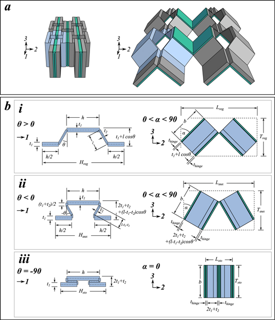
Figure 3. Stowed and deployed honeycomb dimensions. (a) Left: the honeycomb in its reentrant stowed configuration. Right: the honeycomb in its non-reentrant deployed configuration. The strip components are shown in grey, with unit cell highlighted blue. Hinges are shown in green. (b) Detail views of the unit cell, showing dimensions H, L, T, for different configurations. (i) The regular (non-reentrant) configuration where  . (ii) The auxetic (reentrant) configuration where
  . Because the thickness of the strip is significant, we assume that a piece of the l-wall (of length
  ) is consumed in the strip fold. (iii) The stowed configuration. This is the auxetic configuration with
  .
.
Download figure:
Standard image High-resolution imageThese unit cell dimensions can be used to represent an infinite honeycomb, but for a finite cellular structure we must adapt these formulas to take into account edge conditions (e.g. no hinges are attached on the outsides of the honeycomb, and the outermost h-walls are slightly longer). For a honeycomb with number of cells N1 and N2 along the 1 and 2 directions, from inspection one can derive the honeycomb dimensions: (2).


Table 1 shows the dimensions for the SMP deployable honeycomb used in this work. These can be substituted into (2) to predict the stowed and deployed dimensions of the manufactured cellular structures. The dimensions used in this work were selected to easily produce a working demonstrator. The honeycomb cell dimensions are indeed quite large to reduce the impact of manufacturing tolerances. However, the model presented in this work is not limited to the dimensions used here, but could be extended to prototypes with different dimensional values. The limiting factor on scaling is most likely provided by the material thickness. For example, if the structure is scaled up several times its current size the designer will eventually encounter problems folding the resulting very thick hinges. Similarly, the scaling down will eventually lead to the material becoming too thin for classical macroscale engineering applications. Other factors which could also make the model less valid are: (a) the combinations of dimensions that cause the walls to self-intersect (i.e., an un-manufacturable geometry) and (b) large changes in one dimension compared to the others, which could cause a very elongated geometry of the honeycomb.
Table 1. Honeycomb dimensions.
| Dimension | Value |
|---|---|
| h | 20 mm |
| l | 10 mm |
| θ | 30◦ |
| t1 | 2.5 mm |
| t2 | 1.25 mm |
| b | 25 mm |

|
1 mm |

|
0◦ |

|
45◦ |

|

|

|
30◦ |
2.2. Hinge moment
In this section we estimate the opening moment generated by the SMP hinge. The hinges are manufactured in the deployed position, and must be thermoformed into the stowed configuration. During thermoforming an applied moment  produces a stress distribution
  through the thickness of the hinge. We use an engineering curved beam theory model [51] to model the hinge, with figure 4 showing the curved beam geometry considered. The stress distribution due to bending and the location of the neutral axis can be described by equations (3) and (4).


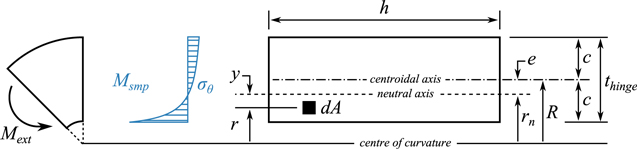
Figure 4. Curved beam geometry (adapted from [51]). An external moment  is applied to the curved beam. This generates the circumferential stress distribution
  .
.  is the hinge opening moment generated by the activation of the SMP.
Download figure:
Standard image High-resolution imageWhen the hinges are activated and the strain is recovered we assume that the distribution of the SMP activation strength  is the same as the distribution of the stored stress
  . The shape memory polymer generates a hinge opening moment equal to
  —i.e.:
  and
and  . Substituting this into (3) we obtain:

From figure 4 it can be seen that  , and we substitute this into (5) to obtain:

We use table 9.1 from [51] with  and
and  to obtain
  . We then substitute e into (4) to obtain
  .
.  . We assume that the maximum tensile strength
  on the convex face is equal to the measured activation strength
  of the SMP, and therefore we substitute
  into (6) to obtain:

From these calculations it is evident that  is very much dependent on the hinge thickness and the position of the neutral axis.
3. Prototype, results and discussions
3.1. SMP honeycomb manufacturing
The particular SMP used in this work consists of a styrene-based polymer synthesised by mixing styrene and butyl acrylate with benzoyl peroxide and cross-linking agent divinylbenzene, followed by stirring at room temperature (further details can be found in [52]). The glass transition temperature of the polymer is ( ) and serves as the shape memory transition temperature. The shape memory action is a one-time transition from a 'learned' temporary shape back to the as-manufactured permanent shape. To create a deployable SMP honeycomb, we used the SMP's permanent shape for the deployed configuration, and the temporary shape for the stowed phase. Heating of the stowed configuration would cause it to return to its deployed configuration. A casting process was used to fix the honeycomb deployed shape during the cure of the polymer. The mixture of styrene, butyl acrylate, benzoyl peroxide and divinylbenzene was poured into moulds and cured at 75 °C for 24 h. To simplify the moulds, the honeycomb was split into strip and hinge components (see figure 3(a)). The hinges and strips were thermoformed into their stowed configurations and subsequently assembled to form the stowed honeycomb. Figure 5 shows the manufacturing process in detail.
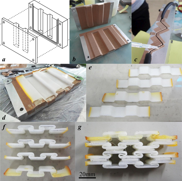
Figure 5. The manufacturing process used to produce the SMP honeycomb. (a) A diagram of the moulds used to form the strip components. The moulds are aligned and held closed by bolts, and washers are used to control the thickness of the component. Rubber tubing (grey line) is used to seal the working section. (b) The working section of the strip moulds is coated with release film. (c) Uncured SMP is poured into the closed hinge moulds before being cured at  for 24 h. (d) The cured part is removed from the strip moulds. (e) The cured part is cut into strips. (f) The components are thermoformed into their stowed shape. (g) The stowed strips and hinges are bonded using cyanoacrylate adhesive to form the stowed honeycomb.
Download figure:
Standard image High-resolution image3.2. Activation force measurement
To estimate the hinge moment generated by the SMP hinges the activation strength of the SMP was determined experimentally using the procedure described in figure 6. An Instron tensile test machine with a temperature controlled chamber (500 N load cell) was used to heat rectangular SMP coupons and measure the activation force generated by the shape memory action. The activation strength is then given by  . Six specimens were tested, using a strain rate of 5 mm min−1 for the stretching phase, and a heating rate of 10 °C min−1 for the recovery phase. The mean value of the activation strength across the whole sample population was 0.49 MPa, with a standard deviation of 0.118 MPa. We substitute the measured
  into (7) to predict a final hinge moment
  .
.

Figure 6. A schematic of the activation strength experiment in force/displacement/temperature space. (1) The specimen was heated to  while held at constant displacement. Thermal expansion of the specimen caused a small compressive load. (2) The temperature was held constant at
  while the specimen was stretched to
  at a constant rate of 5 mm/min. Force was measured. (3) The specimen was held at constant
  and cooled to room temperature. This fixed the temporary shape of the SMP. (4) At room temperature, the specimen was released from the machine grips to release any elastic strain
  . (5) The specimen was reinserted into the grips and heated to
  at a rate of 10 °C min−1 while held at constant
  . The recovery force F1 generated by the specimen was measured.
Download figure:
Standard image High-resolution image3.3. SMP honeycomb deployment experiment
We performed a deployment test of the SMP honeycomb demonstrator to measure the volume of the deployed state relative to the stowed configuration, and compare the volume change to the one provided by the theoretical prediction. The stowed configuration was heated to  using the test machine temperature chamber, and deployment was observed. When no further movement was recorded, the honeycomb was removed from the chamber and the dimensions H, L, and T were measured using Vernier calipers (several measurements were taken per dimension and averaged). Plates were placed under and over the honeycomb to gain a flat surface in order to measure the thickness. Figure 7 shows the stowed and fully deployed configurations.
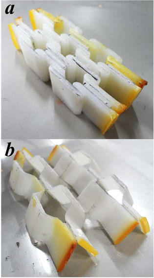
Figure 7. (a) Stowed configuration and (b) deployed configuration of the SMP honeycomb.
Download figure:
Standard image High-resolution imageFigure 8 shows the experimental results compared to the analytical predictions. It is evident that the stowed volume was larger than expected, while the deployed volume showed a lower deployment ratio ( ). It is also possible to observe that both the H and L dimensions were slightly larger than predicted in the stowed configuration (
 ), indicating that the thermoformed state was not completely uniform and more material was consumed in the strip folds than initially expected. In the deployed configuration, the honeycomb expanded fully in the H-direction but not completely in the L-direction. It is worth mentioning that the thickness T was virtually unchanged after deployment, while the dimension H had a final measured
  difference from the theoretical prediction. The hinges did not provide a deployment as effective as the one observed in the strips, likely due to the different thicknesses of the components. As mentioned in section 2.2, the thickness of the hinge and the position of the neutral axis have a large effect on the opening moment generated by the hinge. This is supported by the fact that the strip folds (thickness between
  mm and
  mm) deployed fully while the hinge folds (
 mm) did not. Furthermore, the SMP Kirigami honeycomb demonstrator showed the feasibility of the concept and the general validity of the geometric formulas for the deployment ratio.

Figure 8. Experimental results versus analytical predictions for honeycomb deployment. Left: a surface plot showing the theoretical volume in α, θ space. The line shows the predicted volume change during deployment according to the analytical models. The blue squares represent the measured volume of the honeycomb's stowed and deployed states. Right: the variation of the individual honeycomb dimensions with α and θ (only θ shown on the x-axis).
Download figure:
Standard image High-resolution image
From figure 8 we can see that the deployment path taken by our demonstrator goes from the minimum to the maximum possible volume. The minimum volume configurations correspond to starting α angles of  and
and  , with a maximum starting volume at
  . For the hexagonal centresymmetric open honeycomb configuration used the maximum volume at deployment corresponds to an angle
  . It is however worth noticing that, aside from the one adopted in this work, other possible paths (e.g. starting from a different corner of the design envelope) are possible. This shows that the shape change exhibited by our demonstrator is by no means the only possible motion, and different geometries and SMP materials with multiple activation temperatures could produce different results. The current volumetric or stowage deployment ratio is 5.2 (figure 8), but the theoretical volume surface is based on the fixed honeycomb dimensions used in this work. By changing these dimensions we could achieve an even greater volume change, or we could optimise the honeycomb for a specific task—e.g. deployment along a certain direction.
4. Conclusions
We have manufactured a working demonstrator to test the feasibility of using SMPs to actuate the folds in open Kirigami honeycombs. The concept shown in this paper builds on previous work, to create a model which takes into account the thickness of the honeycomb cell walls. The moment activation can be controlled through the geometry of the hinge and the tupe of shape memory material used. The model shows good agreement with the deployment experiment. In this work we chose our honeycomb configuration to have the largest possible ratio of stowed to deployed volume, but in principle one could optimise the configuration for a specific application or use with different SMPs. For more complex structures, the recent work by Chen et al [53] could be used to model structures with hierarchical and sequential folds.Though the demonstrator successfully deployed, there is room for improvement. While the hinge moment generated by the SMP was large enough to overcome friction and deploy the honeycomb, it is currently very low for practical purposes and would not be suitable for larger structures. The hinge design could be significantly improved by including a paper layer to offset the SMP further from the neutral axis and make it more mechanically effective. A paper-SMP laminate manufacturing method could also allow us to better control the hinges' range of motion and design more complex Kirigami mechanisms.
Acknowledgments
The Authors acknowledge the Engineering and Physical Sciences Research Council for supporting this work through the Centre for Doctoral Training in Advanced Composites at the University of Bristol, UK (Grant no. EP/G036772/1). The work has also been supported by the Sino-UK British Council/China National Science Foundation Partnership for Higher Education Studies.