

Abstract
Liquid drops can bounce when they impact non-wetting surfaces. Recently, studies have demonstrated that the time that the bouncing drop contacts a superhydrophobic surface can be reduced by incorporating ridged macrotextures on the surface. Yet the existing models aimed at explaining this phenomenon offer incompatible predictions of the contact time when a drop impacts multiple intersecting macrotextures, or spokes. Furthermore, it is unclear whether the effects of the macrotexture on the drop hydrodynamics extend to non-wetting surfaces in which direct contact is avoided by a thin vapor layer. Here we demonstrate that the phenomenon observed for macrotextured, superhydrophobic surfaces extends to macrotextured, wettable surfaces above the Leidenfrost temperature. We show that the number of droplets and overall residence time both depend on the number of intersecting spokes. Finally, we compare and contrast our results with mechanistic models to rationalize various elements of the phenomenon.
Export citation and abstract BibTeX RIS
1. Introduction
The design of highly non-wetting surfaces, such as superhydrophobic and superoleophobic surfaces, has received considerable attention due to their ability to mitigate icing [1–3], self-clean [4, 5], and repel liquids [6, 7]. These surfaces typically combine chemical hydrophobicity with microscopic surface texture to achieve high contact angles with low contact angle hysteresis [8]. Much of the on-going work surrounding non-wetting surfaces focuses on the steady state liquid–surface interaction. This work often considers the improvement of the surfaces themselves and the ability to approach an ideal non-wetting surface with a contact angle of  [9, 10]. The study presented here instead focuses on the transient behavior of a drop impinging on a non-wetting surface.
Under certain conditions, a droplet impacting a superhydrophobic surface will spread and subsequently rebound back off the surface [11, 12]. The duration of time the droplet is in contact with the surface governs the amount of mass, momentum and energy that can be exchanged. As such, it is advantageous in certain applications to minimize this contact time [13, 14]. The time that a drop contacts a micro- or nano-textured surface is predominantly dictated by the drop hydrodynamics, and is on the order of the inertia-capillary timescale  , where ρ, R, and γ are the drop density, initial radius, and surface tension, respectively [11]. Microtextures that reduce surface pinning can shorten the contact time [12, 15]; however, this reduction is typically limited by the center of the drop remaining in contact with the surface until it is engulfed by the retracting rim.
To encourage the center of the drop to disengage from the surface earlier in the recoil process, larger-scale structure—often referred to as macrotextures—can be incorporated onto the surface [13]. For example, raised sub-millimeter ridges can break symmetry and fragment the drop while in contact with the surface [13, 14]. Alternatively, sub-millimeter pillar arrays can convert the capillary energy stored in the penetrated array into an upward motion, lifting the center of the spread drop as one piece before it begins to retract [16]. Models developed to understand the source of the contact time reduction on ridged macrotextures focus predominantly on either retraction distances [13] or on fragment droplet volumes [14]. These models lead to different predictions on how drops should interact with multiple intersecting macrotextures, or spokes. Using a 'retraction distance' framework, one might conclude that the contact time should be constant as the number of spokes increases given that all relevant distances remain the same (a condition that breaks down when the distance between spokes approaches the distance of the film spread on the spoke, i.e. when there are more than five equally spaced spokes). However, using a 'fragment volume' framework, one might conclude that the contact time should decrease as the number of spokes increases given that more fragments are produced.
It is also possible to reduce the contact time to nothing at all, provided that liquid avoids direct contact with the surface as it bounces. Drops deposited gently on a clean surface have been shown to bounce off of a thin film of trapped air [17]. Similarly, drops deposited less gently on a sufficiently hot surface can bounce off of their own vapor [18]. Although not technically in contact, these droplets reside microns off of the surface [17, 19] while they spread and retract over the thin gas layer. This residence time also scales as the inertia-capillary timescale τ and is nearly identical to the contact time on superhydrophobic surfaces [20–22]. Energy and momentum can be transferred between the drop and the surface during this time; for example, the heat transfer, albeit reduced from direct contact, can still be significant [23].
In this manuscript, we investigate the dynamics of a water drop impacting a macrotexture surface above the Leidenfrost temperature (figure 1(a)). On a flat heated surface, it has been shown that the drop spreads into a pancake-shape with thickness h and maximum diameter L (figure 1(b)), although how the maximum diameter scales with the impact velocity is less clear [21, 24]. Our study examines seven geometries: a flat surface, as well as one to six evenly spaced spokes extending radially out from a single point (figure 2). Each of these geometries is evaluated for their impact on contact time and how the liquid thickness h, vapor thickness δ, and macrotexture amplitude a interact (figure 1(b)).
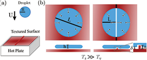
Figure 1. Schematic of drop impact on a substrate with a temperature Ts much greater than the liquid vapor temperature Tv. (a) A drop with radius R impacts a hot solid surface with impact velocity U. (b) On a flat surface, the impacting drop will spread out and retract over a cushion of the drops own vapor. On a spoked surface, the radial symmetry may be broken when the spoke amplitude a is comparable to the liquid film height h and much larger than the vapor layer thickness δ. The broken symmetry can activate the center of the drop to assist in the recoil, reducing the distance that the film needs to retract to leave the interface L.
Download figure:
Standard image High-resolution image
Figure 2. Surface texture explored in this paper. (a) Examples of tessellated surface structures in which various numbers of ridges intersect as spokes. (b) Top–down-view photographs of the milled aluminum substrates used in this study with spoke numbers between n = 2 and n = 6. (c) Schematic of a drop on surfaces with n = 0 (flat) and n = 1 (single spoke). (d) Scanning electron microscopy image of the spoke junction and  view angle of a single spoke. (e) Height profile y(x) of the spoke illustrating an amplitude of
  m.
m.
Download figure:
Standard image High-resolution image2. Methods
The surface textures used in this study are illustrated in figures 2(b) and (c). Spoked junctions are isolated from tessellated surface structures (figure 2(a)) and fabricated from 6061 aluminum bar stock using a 3-axis CNC milling process (figure 2(b)). The various macrotexture can be differentiated by noting the number of spokes n radiating from a central point. For example, parallel ridges that are sufficiently far away from one another, can be modeled as a single long ridge, which would correspond to two spokes radiating out in opposite directions from a center junction (n = 2). This was the geometry predominantly studied in the past superhydrophobic macrotextured experiments [13, 14]. By contrast, a hexagonal or honeycomb tiling corresponds to three spokes radiating out from a center junction (n = 3), square tiling corresponds to n = 4, and triangular tiling corresponds to n = 6. For completeness, we also consider a flat surface milled in an identical fashion (n = 0), and a single spoke (n = 1) that corresponds to the end of a single ridge (figure 2(c)).
Machining capability limits the curvature that can be practically machined at the union on the ridges. As such, this union increases in size as the spoke count increases, but remains a fraction of the impacting drop size. Scanning electron microscopy (SEM) reveals the shape and size of this junction for n = 4, as well as the geometry of a single spoke (figure 2(d)). The final stage of machining sizes the spokes using a  etching tool. Profilometry results quantify the spoke cross-section height profile y(x). Each spoke has an isosceles trapezoid cross-section with an upper base of approximately 100 μm, a lower base of 400 μm, and a height
  m (figure 2(e)). It should be noted that the visual texture away from the spokes is a tool mark from the milling process, not macro-scale texture. Indeed, these tool marks are not large enough to be prominent in the SEM or profilometry data (figures 2(d) and (e)).
To achieve Leidenfrost temperatures, samples are placed on a standard laboratory hotplate and heated to  C (figure 1(a)). A single drop of deionized water is released from a 25-gauge hypodermic needle fixed above the aluminum surface. The initial drop radius R and impact velocity U are measured from high-speed video. Through the course of experiments, the average drop size is R = 1.2 mm with a standard deviation of 3% of this mean. This drop size for water leads to an inertial-capillary time of
  ms. The drop release height is varied to adjust the impact velocity; however most of the results presented in this manuscript are carried out with a drop release height of 85 mm, leading to an impact velocity of U = 1.3 m s−1. Under these conditions, the relative strength of inertial and capillarity forces—as quantified by the Weber number,
  —is
—is  . For context, we find that when
  , the impacting drops do not undergo sufficient recoil to rebound off the surface; whereas when
  , the impacting drops begin to splash.
During impact, the drop dynamics are recorded using a Photron Fastcam SA5 high speed camera at 7000 frames per second. High-speed images are captured from both a side-view perspective, as well as from a top-view perspective. Each video sequence is evaluated using custom image processing scripts developed in Matlab. The combination of both the side and top view allows for a detailed analysis of the interface as it spreads and rebounds on the multi-spoke textures.
3. Results and discussion
The impact dynamics on a Leidenfrost surface are apparent in figure 3. A drop with radius R = 1.2 mm impacts a hot, flat surface (n = 0) with an impact velocity of U = 1.3 m s−1. Side-view images show that the drop deforms into a disk and, rather than wet the surface, begins to retract within 4 ms (figure 3(a)). The drop bounces off of the surface after a residence time of tc = 11.5 ms. Normalizing this time by the inertia-capillary timescale τ confirms that the drop dynamics are equivalent to past studies, both on Leidenfrost and superhydrophobic surfaces, as the drop leaves the surface when  .
.
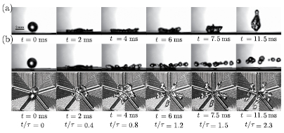
Figure 3. A time series of high-speed images illustrating the impact dynamics for a water drop with radius R = 1.2 mm and impact velocity U = 1.3 m s−1. (a) On a flat surface (n = 0), the drop spreads out and recoils, leaving the surface after 11.5 ms. (b) On a spoked surface (n = 5), side and top views illustrate that the drop develops a 5-fold symmetry, breaks into multiple droplets and leaves the surface after 7.5 ms. Dimensionless times are calculated by normalizing the time t by the inertial-capillary timescale  .
.
Download figure:
Standard image High-resolution imageAn identical water drop (R = 1.2 mm, U = 1.3 m s−1) impacts a hot, 5-pronged surface (n = 5) and behaves quite differently. Side and top-view images show that the drop deforms into a disk and also begins to retract within 4 ms (figure 3(b)). Yet there is a noticeable 5-fold symmetry, with the drop spreading less far on the spokes than between them. The retracting liquid film forms cylindrical ligaments that break up into droplets, all of which leave the surface after a residence time of tc = 7.5 ms. Normalizing this time by the inertia-capillary timescale, leads to a dimensionless residence time of  , a value that is 35% less than that observed for the flat surface.
These results indicate that the presence of the macrotextured spokes can reduce the bouncing time of a drop supported by its own vapor. This conclusion is further supported by plotting the normalized residence time on the different surfaces for the same drop conditions (figure 4). Here the drops impact directly in the center of n spokes and the residence time ranges from  for n = 0 to
  for n = 6. In all cases in which there are spokes (n > 0), the residence time is less than the theoretical axisymmetric limit of
  (dotted line in figure 4). The residence time on the straight ridge macrotexture (n = 2) is also consistent with the contact times observed on superhydrophobic surfaces [13, 14].
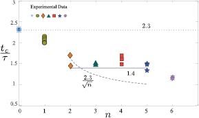
Figure 4. Residence time tc, normalized by the inerita-capillary time τ, varies with the number of spokes n on the heated surface. Past models predict either a constant (solid line) or power-law (dashed line) residence time as the number of spokes increases from n = 2 to n = 5.
Download figure:
Standard image High-resolution imageAlso included in figure 4 are predictions of the relationship between the contact time and the number of spokes (solid and dashed curves). The contact time reduction in the center-assisted model proposed in Bird et al is due to a decreased distance that the film needs to retract before detaching [13]. This distance should remain constant, provided that the radius is less than the distance between spokes (n < 6). Thus the residence time might be expected to also remain constant at the value obtained by Bird et al of  (figure 4, solid line). By contrast, Gauthier et al focused on the fragmentation of the drop on the ridged surface and proposed that the contact time reduction could be linked to the number of uniform droplets produced [14]. Provided that the spokes split the drop into n droplets, it would be expected that the contact time would decrease with increasing number of spokes as
  (figure 4, dashed line).
Although it may appear that the experimental results in figure 4 support one model more than the other, caution is advised as various assumptions used to extend the models become questionable as the number of spokes increase. As figure 3 illustrates, the maximum spreading on the spokes differs from the maximum spreading away from the spokes. In addition, the retraction when n = 5 creates ligaments rather than flat sheets, and finally the impacting drop fragments into ten uniformly-sized droplet rather than five. In the following sections, observations and modeling are provided to elucidate elements of these phenomena.
3.1. Spreading
Upon impact, a drop will spread outward radially from the contact point. This radial expansion occurs on both the flat and the spoked macrotextures, where it is most easily observed from a top–down view (figure 3). We observe that the distance that the drops spread from the contact point, which we refer to as the spreading radius r, depends on the underlying macrotexture. In figure 5, the results of this spreading radius r as a function of time t are plotted for all seven surfaces under the same impact conditions (R = 1.2 mm, U = 1.3 m s−1). Here we have normalized the spreading radius r by the initial drop radius R and normalized the time t by the inertial-capillary timescale τ relative to the time of maximum spreading on the spoke ts. Because we rely on top-view images, we are only able to reliably discern the spreading radius when it is large enough to appear from under the impacting drop, that is r(t)/R > 1. As is apparent in figure 3(b), there is a significant difference in the spreading radius dynamics between the liquid on the spokes and that bisecting the spokes. In figure 5, the results from each surface are denoted by a different symbol, with the results along the spoke denoted with a closed symbol and the results between spokes denoted by an open symbol. On the flat surface n = 0, there is no spoke orientation. To illustrate the degree that the dynamics are axisymmetric, the spreading radius in two orthogonal directions are plotted (blue asterisks and line in figure 5) and shown to be nearly identical.
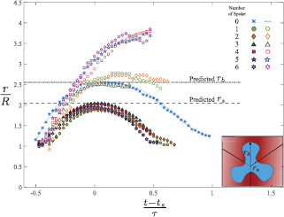
Figure 5. The spreading radius r varies with time t, number of spokes n, and orientation. In the direction of the spokes (closed symbols), the drop spreads to a maximum value rs at time ts. In the direction bisecting the spokes (open symbols), the drop spreads further along the surface to a maximum value rb. The difference in the spreading radius between the spokes and their bisection is manifested as n-fold symmetry from a top–down view (inset schematic). Theoretical predictions for rs and rb (for  ) are denoted by the dashed and dot-dashed lines respectively.
Download figure:
Standard image High-resolution imageIt is noteworthy that the 14 data sets of the spreading radius r(t,n) fall onto one of three main curves (figure 5). The spreading dynamics on the flat surface (n = 0) is remarkably similar to the spreading dynamics between spokes (open symbols in figure 5) when there are three or less spokes ( ). In these cases, the film spreads to a maximum radius
  before retracting. Meanwhile, the simultaneous spreading on the spokes (closed symbols in figure 5) align on a different curve, reaching a maximum radius
  . The spreading on the spokes when n > 3 follows the same dynamics as when
  ; however for these surfaces, the spreading between the spokes (open symbols) follow a third curve that continues to rise throughout the experiment.
The fact that the spreading between the spokes for  is similar to the spreading dynamics without any spoke suggests that the spokes have minimal influence in setting up the shape of the first of these three main curves, but a significant influence on the other two. The maximum spreading distance rb has been previously documented for impact on various flat surfaces, and this literature can provide predictions to what might be expected for impact under the Leidenfrost condition. For drops impacting onto wettable surfaces, the total surface energy is reduced as the drop expands, and therefore the contact angle dynamics have a significant role in the extent of this expansion phase [25, 26]. However, for impact on non-wetting surfaces, the surface energy increases as the drop deforms from the initial spherical shape. It is tempting to conclude that the amount that the drop will deform can be calculated from an energy conservation in which all of the initial kinetic energy
  is converted into surface energy
  . Such a scaling would predict that maximum spreading normalized by the initial radius would scale as
  . However, it has been shown that non-wetting drops impacting hydrophobic surfaces follow a different scaling
  [27]. This scaling has been rationalized by recognizing that accelerations, such as that due to gravity, will flatten drops to a shape in which the hydrostatic and Laplace pressures balance. By analogy, the rapid deceleration of impact will also flatten the drop to a puddle with thickness h. Following Clanet et al [27], if it is assumed that the drop is decelerated from its initial vertical velocity to zero in time R/U, the resulting acceleration acting on the drop is U2/R. At the interface, the pressure balance between the inertial 'hydrostatic' pressure and the Laplace pressure can be described as:

Independently, conservation of mass of the incompressible liquid requires the flatted drop volume (approximated as a disk) to be equal to the volume of the initial spherical drop

Combining these two conservation equations reveals that the maximum radius rb and thickness h can be expressed as
The expression for the maximum radius rb is predicted to have a prefactor of ![$\sqrt[4]{8/9}=0.97$](https://content.cld.iop.org/journals/0953-8984/29/6/064007/revision1/cmaa4e8aieqn031.gif) ; however, for drops impacting on superhydrophobic surfaces, Clanet et al [27] find that their data is better fit to this scaling with a prefactor of 1.1. This minor adjustment is likely related to limitations associated with the assumptions of a uniform deceleration and a cylindrical final state.
; however, for drops impacting on superhydrophobic surfaces, Clanet et al [27] find that their data is better fit to this scaling with a prefactor of 1.1. This minor adjustment is likely related to limitations associated with the assumptions of a uniform deceleration and a cylindrical final state.
This scaling relation is appropriate for drops impacting superhydrophobic surfaces [28]; however it is less clear whether it is appropriate for the Leidenfrost impact presented here. Specifically, in one past study, the results suggest that the maximum spreading follows the  scaling [21]; whereas another more recent studies have argued that scaling relations of
  and
and  are more appropriate [24, 29].
To determine which scaling relationship best describes the dynamics in our system, we vary the impact velocity of drop onto the flat heated surface (n = 0) and measure the maximum spreading radius rb. Figure 6 shows the maximum deformation for impacting drops over a Weber number range between 4–40. It should be noted that the only working fluid considered is deionized water. In the case of higher viscosity flows, the viscous impact drives the system, and the maximum deformation has been shown to be dependent on the Reynolds number [27]. Additionally, there is evidence that the flow of the vapor under the drop can influence drop spreading on Leidenfrost surfaces [24, 30]. The surface that we use has been finished with a cutting tool so that it matches the finish on the other six surfaces. This finish is not optically smooth and therefore may reduce the outward flow of this trapped vapor layer.
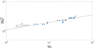
Figure 6. Experimental measurement of the maximum deformed radius rb of impacting drops on a flat surface (n = 0) as a function of the Weber number  . The dashed line denotes the model developed for drop impact on superhydrophobic surfaces from Clanet et al [27].
Download figure:
Standard image High-resolution imageFigure 6 suggests that under Leidenfrost conditions the drop maximum diameter does indeed scale with  . Similar to the results of Clanet et al [27], our data is better fit using a prefactor of 1.1. Relating this expression back to the data shown in figure 5 (
 ), the predicted maximum radius would be rb/R = 2.55 when spoke effects are negligible. This value is depicted by a dot-dashed line in figure 5 and is consistent with the maximum spreading of the drop when n3. From mass conservation, the height of the liquid film would be approximately
  m.
m.
The maximum spreading radius over the spokes rs is noticeably less than the spreading radius on the flat interface rb, suggesting that the presence of the spoke is responsible for this decrease. One might suspect that viscous drag could be responsible for the decreased spread over the spoke; however the vapor film under the drop mitigates the shear stress within the liquid film so that viscous effects are likely negligible. Instead, we explore the possibility that the earlier 'hydrostatic' argument could be extended to the thinner, more highly curved film on top of the spoke. Assuming that the drop spreads out to a thickness h, the film on top of the spokes would have a thickness of h − a, where a is the spoke thickness (figure 1(b)). The radius of curvature across the spread-out drop on the spoke becomes (h − a)/2 so that the balance of inertial and capillary pressures can be expressed as:
Combining this equation with the expression for rb (equation (3)), leads to
It is apparent from this expression that rs decreases relative to rb as the spoke amplitude a increases. Substituting the empirical expression for rb, the spreading radius on the spoke rs can be expressed as
Returning to the data in figure 5—in which  and
and  m—the predicted maximum spreading radius over the spokes is rs = 2.05. This value is depicted by a dashed line in figure 5 and is consistent with the experimentally observed maximum spreading over the spokes (figure 5, closed symbols).
The last set of curves in figure 5 corresponds to the spreading radius bisecting the spokes when  (open symbols). These curves continue to spread beyond the maximum spreading for the flat surface rb. Reviewing the images in figure 3, it is apparent that the excess liquid is gathering along the bisection so that the thickness is locally greater than h. Therefore qualitatively, both the inertial 'hydrostatic' pressure increases and the interface curvature decreases, leading to the observed, larger spreading radius. A more quantitative analysis of this spreading is complicated by the ligament dynamics and is beyond the scope of this manuscript. The transition in film dynamics between n = 3 and n = 4 is explored further in the next section, retraction.
3.2. Retraction
Once the drop spreads to its maximum extent on a non-wetting surface, it begins to retract. Figure 5 illustrates the dynamics of this retraction both on and between the spokes for various number of spokes n. The film on the spoke retracts from the maximum value rs to the initial radius R over a time  . Top-down images of the liquid film at these two points in time, ts and
  , are depicted in figure 7.

Figure 7. Top-view images illustrating the role of the spokes on the film retraction. For each spoke number n (columns), an image is provided at the beginning (t = ts) and end of the film retraction along the spokes. Note that the film forms an angle α at the end of each spoke. When n > 4, the film between spokes retracts into cylindrical ligaments with a length approximately rb and radius rc.
Download figure:
Standard image High-resolution imageThe images in figure 7 give the impression that the film retracts significantly faster along the spoke than off of the spoke. Indeed this difference in speed is used to rationalize the center-assisted recoil of macrotextured surfaces in Bird et al [13]. Capillary forces are expected to retract an inviscid liquid sheet at a velocity V that depends on the initial film thickness h as  [31, 32]. Note that the initially uniform film thickness does not thicken during the retraction, but rather the film remains stationary until engulfed by the retracting rim. This retraction velocity has been used to estimate the contact time of non-wetting drops on flat surfaces with some success [12, 33].
For the macrotextured surfaces explored in this manuscript, the film thickness between the spokes  m is expected to be larger than the film thickness over the spokes
  m. Therefore the retraction velocities between the spokes Vb and over the spokes Vs would be expected to follow
A prominent feature visible as the film begins to retract is an angled notch in the film over each spoke. The angle of this notch or wedge α is identified on several of the images in figure 7. Under the experimental conditions, it appears that this angle is independent of the number of spokes n with a value of approximately  . As the film over the spoke retracts, this angle persists and becomes slightly sharper. Indeed, we attribute a change in retraction dynamics between
  and
and  to this feature. Specifically, when there are 4 or more spokes, the angle between the spokes
  is less than the angle α and causes neighboring notches to overlap as they retract. This overlaped region accumulates liquid and becomes thicker, a result that we attribute to the deviation in spreading curves between values of n in figure 5.
The existence of the angled notch in the film is consistent with the retraction speed over the spoke Vs being faster than the rim retraction speed everywhere else Vb. Indeed, we can make an analogy between the wedge in the retracting film and a Mach cone that surrounds a supersonic object. Retraction waves propagate radially outward from the rim of the liquid over the spoke; however this propagation speed Vb is slower than the rim moves on the spoke Vs so that there is a 'Zone of Silence', or stationary film, beyond the angled wedge. Similarly the angle α, as defined in figure 7, can be related to the inverse sine of the velocity ratio as

In our experiments, the spoke height relative to the film thickness  . Therefore the retraction velocity along the spoke would be expected to be faster than along the bisection by a factor of 1.5, leading to a wedge angle of
  . This angle is smaller than what is observed in figure 7, a discrepancy that may be attributable to a spoke retraction velocity that is accelerating and not yet reached the predicted retraction speed (figure 5).
Under conditions in which neighboring wedge angles do not contact during retraction ( in our experiments), the film between the wedges is still intact. By contrast, under conditions in which neighboring wedge angles overlap during retraction (
 in our experiments), the liquid in the overlapped region accumulates into a cylinder (figure 7). We denote the cylinder radius as rc and the length as the maximum spreading radius between the spokes rb. Rather than retract along the length, these cylinders break up into smaller droplets from the Rayleigh–Plateau instability.
3.3. Fragmentation
An important feature of impact on superhydrophobic ridged surfaces is the fragmentation of the initial drop into smaller droplets [13, 14], a process that occurs after the film retracts over the spokes (figure 3). Figure 8 shows a top view of the droplets that leave the surface under the conditions in which the residence time reduction was measured (figure 4). As has previously been documented for superhydrophobic surfaces, the liquid recoils off of a flat surface (n = 0) as a single drop, two droplets leave when n = 2 and three droplets leave when n = 3 [13, 14]. Less expected is the number of droplets produced for the other the geometries. Two smaller droplets accompany a larger drop after breakup on a single spoke (figure 8, n = 1), and when n > 3, the number of droplets nd can far exceed the number of spokes n.
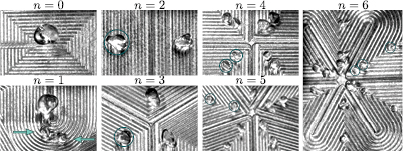
Figure 8. Image of each surface at the end of the residence time illustrating the multiple daughter droplets that fragmented from the single initial drop. Arrows identify two smaller droplets when n = 1, and circles identify single, double, and triple droplets fragmented along a single spoke bisection.
Download figure:
Standard image High-resolution imageThe images in figure 8 show a striking uniform size distribution of daughter droplets for n > 1. For the n = 2 and n = 3 geometries, the initial drop fragments into the expected one daughter droplet per spoke. These daughter droplets are of approximately equal size. In the n = 4 and n = 5 geometries, the daughter droplet count becomes twice the spoke count (figure 9). In the n = 6 geometry, we observe a tripling effect with three droplets per spoke. Even when the number of droplets doubles or triples, the size of the fragmented daughter droplets are approximately equal size to one another.

Figure 9. The number of fragmented drops nd varies with the number of spokes n.
Download figure:
Standard image High-resolution imageIn an effort to understand and predict the doubling and tripling behavior, we develop a scaling argument based on the Rayleigh–Plateau instability. Specifically, the cylindrical geometry of the ligaments that immediately precedes the droplet breakup—as seen in figure 7—will be unstable and can breakup into a series of droplets provided that its length is longer than its circumference [8]. The breakup of finite, retracting ligaments are known to require significantly larger aspect ratios to break-up into more than one droplet [34, 35]. Yet the ligaments that form on the spoked surfaces, appear to be neither significantly expanding nor retracting when they break up (figure 5). Under these conditions, a criterion for the formation and size of droplets would be that the surface energy decreases. We model the ligament before breakup as a cylinder with hemispherical caps and after breakup as multiple equal-sized spherical droplets such that the total volume before and after breakup is conserved. By equating the surface area before and after breakup, we find that the transition between single and double drops per spoke is estimated to occur when the ligament length rb is 7.46 times radius of the cylindrical ligaments rc, and the transition between double and triple is estimated to occur when  (figure 10). Note that due to end effects, these transition values are slightly different than would be estimated using the most unstable wavelengths from linear stability analysis for an infinitely long cylinder [36, 37].

Figure 10. The measured aspect ratio  for drops that form ligaments (n > 3) increases with the number of spokes n and is consistent with the surface energy model for the drop doubling and drop tripling regimes. The solid line corresponds to equation (10), which slightly overestimates the aspect ratio.
Download figure:
Standard image High-resolution image
The aspect ratio  of the cylindrical ligaments prior to breakup (figure 7) can be predicted based on their length rb and the number of spokes n. From mass conservation, the volume of the initial drop is equal to the collective volume of the n cylindrical ligaments
The aspect ratio of the liquid cylinder can thus be estimated as
The spreading radius between the spokes rb/R is reported in figure 5 for different values of n. When  , the corresponding spreading radius increases to approximately rb/R = 3.5, and the aspect ratio is predicted to follow
  . This curve, along with the drop doubling and tripling transition points, is plotted in figure 10. The curve lies in the doubling region when n = 4 and the drop tripling region when n = 5 and n = 6. We can also calculate the aspect ratio γ directly from the experiments, and the averages across ligaments are also plotted in figure 10. These direct measurements have slightly lower values of aspect ratios γ than the prediction, which is likely due to our assumptions of the ligament shape. The directly-measured aspect ratios γ lie in the predicted doubling region when n = 4 and n = 5, and tripling region when n = 6, consistent with the fragmentation results.
4. Conclusions
This study investigates if and how structured surface macrotextures affect the residence time for drops impacting a wettable surface heated above the Leidenfrost temperature. Our findings demonstrate that ridged macrotexture can indeed reduce this residence time; for a flat surface (n = 0) and ridged surface (n = 2), the results match those described in the literature for superhydrophobic surfaces [13, 14], suggesting that a similar hydrodynamic mechanism is responsible for the reduction. These results include a maximum deformation on the flat surface that scales as  . A key component of our study is the investigation of impact dynamics on non-wetting raised spokes, as a means to better understand impact on tessellated surface structures and to evaluate discrepancies between two existing mechanistic models. We find that both models fail to capture certain aspects of the impact dynamics that are critical to assessing both the residence time and the number of droplet that leave the surface. Specifically, we highlight three features. First, the maximum spreading of the film in the presence of spokes is different for the film covering the spokes than the film away from the spokes. Second, the existence and prevalence of an angled notch, or wedge, in the liquid film over each spoke. Finally, we highlight the gathering of liquid into a radial array of ligaments as the number of spokes increases. These ligaments can lead to a significantly larger number of uniform droplets than might be expected to form as the liquid recoils from the surface. We develop mechanistic models to rationalize each of these aspects, and the results are consistent with our experiments.
Acknowledgments
We thank Kripa Varanasi for helpful early-stage discussion. We also thank Robin Song for assistance with the data collection and Bob Sjostrom for milling the surfaces. CP acknowledges support from General Electric and SS support from Boston University's Dean's Catalyst Award.