

Abstract
We propose a lamina-shaped metamaterial absorber based on the coherently coupled weak resonances of high-order Helmholtz resonators in this work. Such an ultra-thin lamina metamaterial can achieve broadband tunable absorption (maximal absorption >0.9), which exhibits near-perfect ventilation performance (ventilated area ratio >0.8, ratio of wind velocity >0.95). Benefiting from coherently coupled weak resonances between units with different structure parameters, the lamina metamaterial presents a broadband absorption (506–659 Hz with 2 × 3 units and 480–679 Hz with 2 × 4 units). The ultra-thin and simple structure shape of this sound absorption metamaterial lamina leads to not only an efficient ventilation performance but also high potential value in various scenarios of ventilated sound absorption, especially in ventilation tubes with high noise.
Export citation and abstract BibTeX RIS
1. Introduction
Over the past few decades, noise pollution has become increasingly severe, and caused significant harm to public health [1, 2]. Therefore, the reduction of vibration and noise has become a very active and important research subject. Conventional sound absorption materials such as foam and porous plates have an almost perfect absorption in high-frequency, but poor absorption performance in low frequency (usually < 1000 Hz) [3–6]. The emergence of acoustic metamaterials, which refers to artificial structural materials with unconventional acoustic properties, provides a new solution to the problem of low-frequency noise reduction. After a fast development over the last 20 years, acoustic metamaterials have made significant progress in various areas and become necessary building blocks for acoustic focusing [7–9], imaging [10, 11], vibration and noise reduction [12–17], and a variety of topological phenomena [18–21]. Acoustic metamaterials for vibration and noise reduction are divided into sound-insulating metamaterials [22–24] and sound-absorbing metamaterials. The former one can effectively isolate sound transmission based on high reflection of sound back to the incident direction, which may cause secondary noise pollution in the incident direction. On the other hand, the latter could realize noise reduction by converting vibration energy to heat based on the thermal viscosity loss of air in resonance structures. Therefore, sound absorption metamaterials could be a better choice for noise reduction in most scenes.
In the relevant studies, sound absorption metamaterials are further divided into unventilated and ventilated ones. The 'traditional' unventilated sound absorption metamaterials [25, 26] only allow sound waves to enter the structure from one side of the sound absorber. While this type of sound absorber can achieve efficient and broadband sound absorption at low frequencies, it typically requires a rigid backing blocking fluid flow. This limitation prevents air, water, and other fluids from flowing freely between both sides of the sound absorber, which could be quite important in realistic situations, such as ventilating system, air cooling system, etc. However, when the reflective backing is removed to allow the liquid to flow, the sound absorption performance of the absorber will be greatly degraded whose absorption is usually below 0.5 [27]. Therefore, it is quite difficult for traditional metamaterial absorbers to satisfy both the requirement for ventilation and noise reduction. Meanwhile, ventilated sound absorption metamaterials [28–31] do well in this challenge, which has received lots of attention in recent years. In contemporary studies, the ventilation area ratio (ventilation path area/whole area) is still limited (usually less than 70%). Although there are some sound absorbers with a 100% ultra-ventilated area ratio [32, 33], these designs need extra structures on the outside of ventilated channels which require extra modification of the channels, and their installation also has potential safety issues. Therefore, near-perfect sound absorption (>90%) and high ventilation area ratio (>80%) absorber without extra structures remains a challenge in this rapidly developing research field.
2. Results and discussion
2.1. Structure design
In this work, we will first conceptually propose an ultrathin sound absorption lamina, and then will experimentally verify such metamaterial absorbers based on the lamina units. The lamina unit, based on weak coupling of high-order Helmholtz resonances, is shown in figure 1(a). In our example, a periodic unit, enclosed by the red dashed line, has a length of 74 mm. Adjacent units are coupled to each other via a notch of length A (the outmost coupling corners are sealed for a finite structure). In figure 1(a), the periodic unit in the red-dotted box consists of the basic structure in the blue-dotted box through a fourfold rotation. The basic structure is constructed by two series-connected embedded Helmholtz resonators, whose sketch and internal structural parameters are shown in figure 1(b). Here, the wall thickness w = 2 mm, the width of the outer cavity l = 22 mm, and the width of the lamina Lx = 146 mm are chosen for the present study. A schematic diagram of a finite sample of 2 × 3 units is shown in figure 1(c) for a direct visualization. One suitable application scenario of this sound absorber is also illustrated in figure 1(d), where the lamina is located on the inner wall of the ventilation duct with a high ventilation area ratio. Benefitting from the ultra-thin thickness of this metamaterial lamina, the fluid in the ventilation duct could flow freely. As the sound wave near the resonant frequency travels through this metamaterial lamina, the majority of sound energy is drawn into the lamina and dissipated due to thermal viscosity loss. The embedded Helmholtz resonator can effectively extend the neck length of the primary Helmholtz resonator, leading to a decrease in resonance frequency. Then connecting a central Helmholtz resonator and two embedded Helmholtz resonators in series, the resonance frequency can be further reduced. Consequently, subwavelength sound absorption can be achieved. Our results demonstrate this sound absorption lamina can operate at a high ventilation area ratio condition (>80%), and achieve quasi-perfect low-frequency sound absorption in broadband and near-perfect ventilation performance.
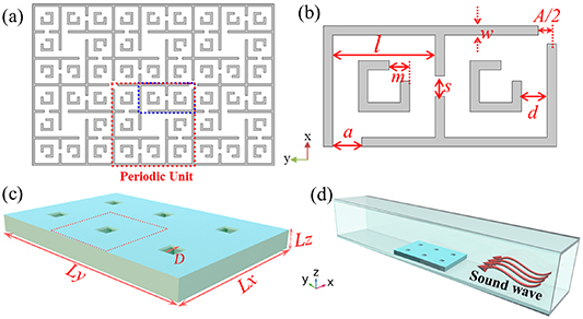
Figure 1. Schematic diagram of metamaterial lamina and working scenario. (a) A cross-sectional view (x-y plane) of a lamina consisting of 2 × 3 units. The periodic unit is enclosed in a red dashed box and the basic structure is enclosed in a blue dashed box. (b) The schematic diagram and geometric parameter of the basic structure. (c) Three-dimensional plot of a metamaterial lamina consisting of 2 × 3 units. (d) Schematic diagram of the working scenario.
Download figure:
Standard image High-resolution image2.2. Simulation and experimental results
To verify the acoustic performance of the designed sound absorber, we chose three sets of geometrical parameters for both simulations and experiments, the parameters are given in table 1. We use the pressure acoustics module of the finite element software COMSOL Multiphysics to perform numerical analysis. The inner surface of the waveguide and the wall of the sample are fixed as hard boundaries of the acoustic field in the simulation. The parameters for the physical properties of air are set as follows for the normal temperature and pressure: the density of air ρ= 1.2 kg m−3, the speed of sound c= 343 m s−1, the dynamic viscosity coefficient μ= 18.5 μPa·s, the thermal conductivity κ= 0.024 W (m K)−1, the heat capacity at constant pressure Cp= 1000 J (kg·K)−1. For comparison with experiments, as will be discussed later, the samples are placed in a hard-boundary rectangular waveguide with a cross-section of 146 mm × 146 mm. The simulation results for the three samples are shown as the solid lines in figure 2(a), where the resonance frequencies for samples 1, 2, and 3 are 605 Hz, 728 Hz, and 899 Hz, respectively. The corresponding maximum sound absorptions are 0.92, 0.98, and 0.94. For the three samples described above, the thickness Lz is 16.8 mm, so the ventilation area ratios of the three samples are 88.65%. Furthermore, the proportion of resonance wavelengths to thickness (Lz) for each of the three samples stands at 33.75, 28.04, and 22.71, in that order. Moreover, these sound absorbers occupy a volume of 0.29%, 0.51%, and 0.96% of the cube of the corresponding wavelength, respectively. To reveal the physics behind the absorption, we plot the acoustic pressure distributions at the resonant frequency in figures 2(b)–(d). Perfect absorption can be known to benefit from the fundamental unit's local resonant coupling and weak coupling between adjacent units.
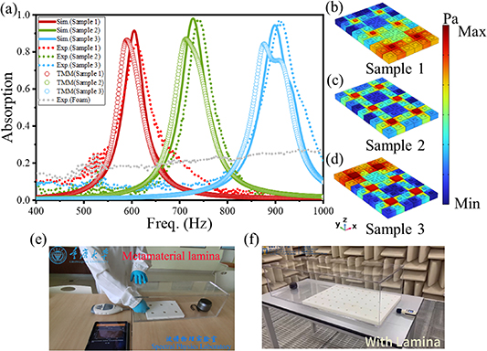
Figure 2. (a) The absorption of lamina metamaterial, where solid lines represent the simulation results, dots represent the experimental results, circles represent the results from transfer matrix calculation, and the gray dotted line represents the experimental data of BASF foam. (b)–(d) The distribution of the acoustic pressure fields at the resonant frequencies (605 Hz, 728 Hz, 899 Hz). A static image of the demonstration video with (e) sample 2 and (f) a large-scale sample (Multimedia view).
Download figure:
Standard image High-resolution imageTable 1. Parameters of the three sets for the metamaterial structure.
| Lx | Ly | Lz | l | w | a | A | d | D | m | s | |
|---|---|---|---|---|---|---|---|---|---|---|---|
| Sample 1 | 146 mm | 218 mm | 16.8 mm | 22 mm | 2 mm | 4.5 mm | 7.6 mm | 4.2 mm | 10 mm | 5.1 mm | 2.2 mm |
| Sample 2 | 146 mm | 218 mm | 16.8 mm | 22 mm | 2 mm | 6.2 mm | 7.8 mm | 5.5 mm | 15.5 mm | 4.4 mm | 1.4 mm |
| Sample 3 | 146 mm | 218 mm | 16.8 mm | 22 mm | 2 mm | 9 mm | 9 mm | 5.2 mm | 22 mm | 4 mm | 5.5 mm |
To verify the simulation results, the acoustic performance of the laminas fabricated with polylactic acid (PLA) by a 3D printer are measured in a square impedance tube [34]. The experimental data is shown in figure 2(a) as the dotted lines (red, green, and cyan), which agree well with the simulation results. Moreover, compared with sound absorption foam (Basotect G+, BASF) of the same profile, the metamaterial lamina presents excellent sound absorption performance around the resonant frequency. Furthermore, both experimental and simulated results point out this metamaterial lamina could realize selective sound absorption in a wide region at a low frequency (∼605 Hz–899 Hz). In addition, we performed a demonstration of noise reduction using sample 2 at 740 Hz, with a sound transmission loss (STL) of about 26 dB as shown in figure 2(e) (Multimedia available online).
2.3. The effective model of metamaterial lamina
The physical model of this lamina structure can be interpreted using the transfer matrix method (TMM). The transfer matrix of the ith layer is defined as:
in which  represents the acoustic pressure forward (backward) at the front end of the ith layer, or the sound wave forward (backward) at the back end of the (i−1)th layer. The transfer matrix of the ith layer structure can be expressed as:
ti (ri ) represents the transmission (reflection) of the i-layer structure when sound waves incident in the y-direction, while ti' (ri') represents the transmission (reflection) of sound waves incident in the opposite direction. The periodic units for sample 1, sample 2, and sample 3 in the first part exhibit a fourfold rotational symmetry, with ti = ti' and ri = ri'. The total transfer matrix for a lamina with n layers is as follows: T = TnTn− 1 ... T2 T1, so the transmission matrix of the sound absorption lamina composed of identical 2 × 3 units can be expressed as
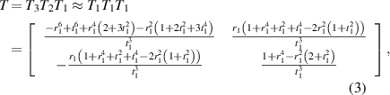
which can obtain the transmission and reflection coefficients,
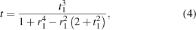
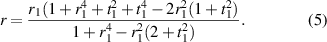
Then, according to the law of energy conservation, the sound absorption coefficient can be obtained

as shown in figure 2(a) with cycle lines.
2.4. The influence of parameters on sound absorption
To obtain a better understanding of the selective sound absorption performance of this lamina structure, the relationship between structural parameters and absorption coefficients is also investigated based on controlled variables. The initial values of the geometric parameters are set as Lx = 146 mm, Ly = 218 mm, Lz = 16.8 mm, l = 22 mm, w = 2 mm, a = 3.6 mm, A = 8.1 mm, d = 4.2 mm, D = 12.3 mm, m = 4.5 mm, s = 1.7 mm, where Lx, Ly, l, and w are fixed values. We find that the parameters a, d, D, and Lz have a strong influence on the absorption. Figure 3(a) shows the absorption spectrum of the parameter a. As a is increased, the resonant frequency shifts significantly to the high frequency, and the absorption and the bandwidth of the absorption also increase. Figure 3(b) shows the relationship between the parameter d and the absorption. As d increases, the resonant frequency first shifts significantly to a higher frequency and then tends to a limit. In addition, the absorption coefficient first increases and then tends to approach a limit, while the absorption bandwidth becomes significantly broader. The relationship of the spectrum between the parameter D, frequency, and absorption coefficient is shown in figure 3(c). From this Figure, it can be seen that with increasing D, the resonant frequency, the sound absorption coefficient, and the absorption bandwidth all increase significantly. Figure 3(d) shows the influence of the sample height Lz on the absorption. As the Lz is increased, the absorption peak shifts to a lower frequency, while the peak absorption first rises and then falls. On the other hand, the geometric parameters A, m, and s only have little influence on the absorption spectrum, as can be seen in figure S2 of the supporting materials.
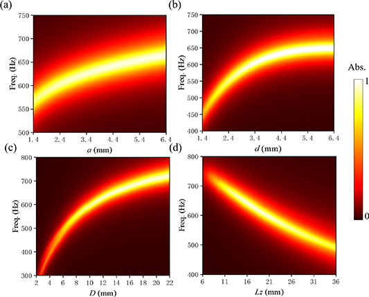
Figure 3. (a)–(d) The influence of parameters a, d, D, and Lz on the sound absorption. The light bar displays the migration of the resonant frequency with changes in parameters.
Download figure:
Standard image High-resolution image2.5. Broadband sound absorption
To obtain broadband absorption, we further construct the lamina with various resonance units. Here two laminas comprising 2 × 3 units and 2 × 4 units are optimized for broadband sound absorption in the corresponding frequency range, in which Lx= 146 mm, l= 22 mm, and w = 2 mm are kept unchanged for the two laminas. Black solid lines in figure 4(a) display optimization simulated results of 2 × 3 units, where sound wave propagates along the +y direction. From 506 to 669 Hz, the absorption coefficient of this lamina is greater than 0.5, whose average sound absorption rate is 0.64. The black dotted line of figure 4(a) presents the corresponding experimental result, which is in good agreement with the simulation. We also independently simulated and analyzed the acoustic performance of units 1–6 separately, as shown in the group of colored curves in figure 4(a). The sound absorption coefficients of all six single units are consistently less than 0.5. Because of the coherently coupled weak resonances [35] between these units, the overall absorption coefficient and bandwidth increase significantly. In comparison to figure 2(a), the working bandwidth (absorption coefficient >0.5) is significantly increased by decoupling the resonances without altering the number of units. The optimization results for a sample consisting of 2 × 4 units are shown in figure 4(b), a solid black line shows the simulation result. In the band of 483–683 Hz, the simulated absorption coefficient is higher than 0.5 whose average absorption coefficient is 0.67. The black dotted line represents the experimental result of the corresponding sample, which is well in accord with the simulations. Numerical analysis of the independent unit labeled 1–8 is also carried out. When each unit acts alone, the absorption coefficient is substantially small. Both experimental and simulated data demonstrate the absorption value and bandwidth of the assembling lamina could be efficiently increased by the weak coupling. Due to the asymmetric of the structures, the scattering of sound waves is asymmetric when they enter from the +y or −y direction, this leads to the asymmetric absorption of sound waves. Experimental and simulation results of sound incidence along the −y direction are shown in figures S3 of supplementary material.

Figure 4. The sound absorption of the lamina with assembling units (a) 2 × 3 units and (b) 2 × 4 units, where the red arrows represent the incident direction of the sound wave and the black blocks represent units with different structure parameters.
Download figure:
Standard image High-resolution imageBy comparing the results of 2 × 3 and 2 × 4, it is found that adding decoupling units to the direction of acoustic propagation can effectively improve the average sound absorption coefficient and bandwidth. Enhancing sound absorption can also be achieved by compromising some ventilation efficiency by symmetrically placing two laminas on the waveguide's internal wall. We simulated this scenario and observed an enhancement in the sound absorption coefficient. For more information, consult figure S4 in the supplementary materials.
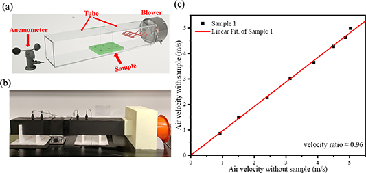
3. Ventilation performance
The ventilation performance of this lamina structure is also explored in this work. Figure 5(a) shows the schematic diagram of the ventilation experiment and figure 5(b) shows the experimental setup. A metamaterial lamina is attached at the inner bottom surface of the duct with an anemometer for obtaining the speed of airflow provided by the blower. The ventilation performance is represented by the ratio of wind speeds (the ratio of wind speed with and without samples). The ventilation experiment data of the Sample 1 are presented in figure 5(c). Black squares are the experimental measurement results, and the solid red line is the best-fit curve whose slope approximates 0.96. For experimental comparison, the ventilation efficiency of sample 1 was simulated using COMSOL Multiphysics' fluid dynamics, with results shown in supplementary material figure S5.
Figure 5. (a) Schematic diagram of ventilation experiment; (b) image of ventilation experimental device; (c) the experimental ventilation data of sample 1.
Download figure:
Standard image High-resolution image
The experimental results of the ventilation performance of sample 2, sample 3, and the sample with assembling 2 × 3 units and 2 × 4 units are shown in figure S6. For the five samples above, the ratios of the wind speeds are all larger than 95%, which points out the metamaterial lamina has excellent ventilation ability. Experimental results for ventilation performance indicate that the insertion of our sound absorption lamina has almost no influence on the ventilation performance of the duct.
4. Conclusion
In this work, an efficient sound absorption metamaterial lamina working at low frequencies (<1000 Hz) is presented, which simultaneously achieves ultra-ventilated performance, with a ventilation area ratio of more than 80% and a measured wind speed ratio of more than 95%. Furthermore, broadband absorption based on coherently coupled weak resonances is also achieved by breaking the symmetry of the lamina metamaterial. To further demonstrate the potential of our lamina metamaterial in practical scenarios, we have also designed a large-size sample for a duct of the realistic size and experimentally confirmed its sound absorption performance (details are provided in supplementary Note 5 and demonstration in figure 2(f) (Multimedia available online)). In summary, with our design, this lamina metamaterial can be customized and employed for versatile noise reduction applications, taking a significant step towards developing potential applications of metamaterials in realistic scenarios. In addition, the lamina metamaterial has an ultrathin and compact profile, which overcomes the major contradiction for previous acoustic metamaterials between the ventilation and absorption performance.
Acknowledgments
This research was supported by the National Natural Science Foundation of China (12374342, 11974067) and the Sharing Fund of Chongqing University's Large-scale Equipment. Xiaoxiao Wu also acknowledges the support from the Quantum Science Center of Guangdong-Hong Kong-Macao Greater Bay Area (Guangdong), Guangzhou Municipal Science and Technology Project (No. 2023A03J0003), Guangzhou Municipal Science and Technology Project (No. 2024A04J4351), and Research on HKUST(GZ) Practices (HKUST(GZ)-ROP2023021).
Data availability statement
The data cannot be made publicly available upon publication because they contain commercially sensitive information. The data that support the findings of this study are available upon reasonable request from the authors.