

Abstract
A single step direct picosecond laser texturing process was demonstrated to be able to obtain a superhydrophobic surface on a nickel substrate, a key material for mold fabrication in the manufacture of various devices, including polymeric microfluidic devices. A two-scale hierarchical surface structure of regular 2D array micro-bumps with nano-ripples was produced on a nickel surface. The laser textured surface initially showed superhydrophilicity with almost complete wetting of the structured surface just after laser treatment, then quickly changed to nearly superhydrophobic with a water contact angle (WCA) of 140° in less than 1 d, and finally became superhydrophobic with a WCA of more than 150° and a contact angle hysteresis (CAH) of less than 5°. The mechanism involved in the process is discussed in terms of surface morphology and surface chemistry. The ultra-fast laser induced NiO catalytic effect was thought to play a key role in modifying the surface chemistry so as to lower the surface energy. The developed process has the potential to improve the performance of nickel mold in the fabrication of microfluidic devices.
Export citation and abstract BibTeX RIS
1. Introduction
In nature, there are a large number of material structures whose properties are superior. For example, the lotus leaf surface possesses a superior self-cleaning effect. The surface of the lotus leaf enhances the hydrophobic properties by a two-scale hierarchical surface structure ranging from the micro- to nanoscale. The water contact angle (WCA) and contact angle hysteresis (CAH) are influenced by both surface chemistry and surface topology [1]. The Wenzel [2] and Cassie–Baxter [3] models indicate that a rough surface is critical for enhancing hydrophobicity and hydrophilicity. Two major categories of approaches are being used for surface patterning, namely, the top-down and bottom-up approaches. Top down approaches include lithographic, template-based technique [4], plasma treatment [5, 6] and laser treatment of the surfaces [7, 8]. Bottom-up approaches are mainly on the processes involving self-assembly and self-organization [9, 10]. As a top-down method, laser processing has received much attention and is developing rapidly. Ultrafast lasers have been increasingly used as a tool for surface texturing. By laser ablation with ultra-short pulses in the pico- or femto-second range, well controlled surface textures can be obtained [11–13] for the creation of certain surfaces with desirable properties. Hitherto, a lot of research studies have been conducted on laser surface texturing of different materials such as metals [11, 12, 14–16], silicon [17], and polymers [18, 19] for the modification of their wettability to hydrophobicity or even superhydrophobicity. Furthermore, a systematic review [20, 21] has been conducted on laser superhydrophobic surface fabrication processes. The mechanisms on wettability conversion of micro-nano structured metallic surfaces from super-hydrophilicity to super-hydrophobicity have also been well reported [12, 22, 23]. It was found that the mechanism involved in the wettability conversion is dependent on the specific material to be investigated. For stainless steel [12], it was proposed that the change in wetting behavior was correlated with the amount of carbon on the structured surface, which was produced by the decomposition of carbon dioxide into carbon with laser irradiation produced active magnetite as a catalyst. For copper [22], the wettability conversion from hydrophilic to highly hydrophobic was caused by the adsorption of organic matters from the surrounding atmosphere. For Ni micro-nano cones array surface fabricated with electro-deposition method [23], the transition from super-hydrophilicity to super-hydrophobicity was proposed to be attributed to the formation of nickel oxide on the surface. Nickel is an important engineering metallic material for the fabrication of mold for the mass manufacture of various polymer devices, including microfluidic devices. The hydrophobic or superhydrophobic property is expected to facilitate demolding during the polymer injection molding process. In addition, the micro/nano surface structures produced on the Ni mold surface can be transferred to the molded polymer surfaces so as to modify the polymer surface wettability, which are desirable for the fabrication of microfluidic devices such as micro-mixers, micro-valves, etc. So far, only a few studies [24–26] have been conducted to employ fs lasers to produce micro/nanostructures on Ni surface so as to improve its optical absorption and hydrophobicity.
In this investigation, a ps laser was employed to fabricate the surface textures on a Ni surface. A two-scale hierarchical surface structure consisting of a regular 2D array of micro-bumps superimposed with nano-ripples was produced. The laser textured Ni surface was found to be superhydrophilic with a WCA of less than 10° just after laser irradiation, and then quickly changed to nearly superhydrophobic with a WCA of 140° in less than 1 d, and finally became the superhydrophobic after 30 d with a WCA of more than 150° and a CAH of less than 5°. The conversion from the original hydrophilic nickel surface with a WCA of 82° to a superhydrophobic nickel surface with a WCA of 159° can be explained by laser induced surface morphology and surface chemistry, which were characterized with scanning electron microscopy (SEM), atomic force microscopy (AFM), and x-ray photoelectron spectroscopy (XPS). The ultra-fast laser induced NiO catalytic effect was thought to play a key role in modifying the surface chemistry through rendering carbon formation resulting in lowering the surface energy.
2. Experimental methods
An electroplated Ni plate with a thickness of 1 mm was used for laser surface treatment under different processing parameters. Before laser treatment, the Ni samples were cleaned with acetone and methanol in an ultrasonic bath. The laser surface treatment experiments were conducted with a 1.06 µm 10 W, 10.3 ps laser system (Time Bandwidth; Duetto), with a repetition rate ranging from 50–8200 kHz. The laser beam has a Gaussian profile with a TEM00 (M2 < 1.3) spatial mode. The divergence of the beam is less than 0.3 mrad. The raw laser beam is linear polarized and has a diameter of 7 mm (@ 1/e2), which is directed to the sample surface using a galvanometric scanner with a telecentric f-theta lens. The focus lens has a 100 mm focal length and the focused beam diameter on the sample surface is around 25 µm. With the control software, the laser system can machine different patterns, such as a line, circle, and hatching on the sample surface. The galvanometer scanner has a maximum scanning speed of 2000 mm s−1. The surface treatment was conducted through raster scanning of a designed hatched pattern with the focused laser beam. The effects of laser power density, repetition rate, scanning speed, pass number, and hatching density on the fabricated surface patterns in terms of morphology, feature size, and pattern uniformity were investigated.
SEM and AFM were employed to characterize the morphology of the laser induced surface structure. The sessile drop method with VCA Optima (VCA-2500XE AST products, Inc.) was employed to measure the surface contact angle. A syringe with a capillary tip was used to create a water droplet with a volume of 1 µl, which was subsequently detached gently onto the substrate. A precision camera and advanced PC technology were used to take a snapshot of the image of the droplet and to determine the tangent line for the contact angle measurement. Through measuring the advancing and receding contact angles of the growing and shrinking droplet, the CAH was derived. The elemental composition and chemical status on the sample surface were measured with XPS (ESCALAB 250Xi, Thermo Scientific) and a Raman imaging microscope (inVia Raman Microscope, Renishaw).
3. Results and discussion
The laser surface treatment was conducted through raster scanning of a designed hatched pattern (figure 1(a)) with the focused laser beam under different laser parameters such as different laser power density, repetition rate, scanning speed, pass number, and hatching density. With the identified optimum laser surface texturing parameters of a laser fluence of 1.43 J cm−2, repetition rate of 1 MHz, scanning speed of 500 mm s−1 for 30 passes, and hatching density of 25 µm in both directions on a cross hatched pattern, a uniformly distributed, regular 2D array of micro-bump texture was produced on the Ni substrate with an area of 20 × 20 mm. As shown in figure 1(b), the laser produced surface texture was quite consistent and uniform. Figure 1(c) shows the SEM image of the laser textured Ni surface, where a regular 2D array of micro-bumps was produced with bump diameters of 15 µm, an array period of 25 µm, and bump heights of about 9 µm. The enlarged image (inset of figure 1(c)) shows the formation of the periodic ripples consistently covering the surface of the micro-bumps. The ripples were measured to have a period of 800 nm and a modulation height of around 220 nm with AFM measurement as shown in figure 1(d).

Figure 1. Laser fabricated 2D array microbump based textures via raster scanning of the designed hatched pattern (a), overview photo (b), SEM image (inset: image further magnified) (c), and AFM measurement on the ripple feature (d).
Download figure:
Standard image High-resolution imageIn the study, the laser fluence was 1.43 J cm−2, which was somewhat higher but near the Ni picosecond laser ablation threshold of 1.2 J cm−2 [27]. Similar to past studies, periodic surface ripples with a pitch of near laser wavelength were produced after a number of laser-shot irradiations with a laser fluence in the vicinity of the single pulse ablation threshold [28, 29]. It was suggested that these ripples emerged from a standing wave created by the interference of the incident laser light with the scattered waves from a surface disturbance [30]. Subsequently, the melting threshold of the surface was periodically surpassed, and the subsequent fast resolidification of a thin layer of molten material resulted in the ridged structure. The laser intensity should be high enough for the interference pattern to be etched on the target surface. The first pulse initiated arbitrary surface roughening, while the ensuing pulses created periodic ripples [31]. The spatial ripple period was determined by the laser wavelength, polarization, and incident angle of the radiation. As shown in figure 1(c), the two-scale micro-nano hierarchical surface pattern was produced, which is expected to be beneficial in increasing the WCA. However, the laser textured Ni surface was found to be superhydrophilic with a WCA of less than 10° just after laser texturing process, and the textured surface then quickly changed to nearly superhydrophobic with a WCA of 140° within 1 d. After 30 d, the laser textured Ni became stably superhydrophobic with a WCA of more than 150°. Figure 2 shows the measured WCA of the laser textured Ni as a function of the timing.
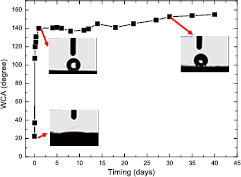
Figure 2. The measured WCA of the laser textured Ni as a function of the timing.
Download figure:
Standard image High-resolution imageFigure 3 shows the WCA of original and laser treated Ni substrates after 30 d from laser treatment process. The WCA of the original Ni is 82.3° whereas the WCA of laser treated Ni increased to more than 150°, indicating that a hydrophilic surface has been converted into a superhydrophobic surface via laser surface texturing. Figure 3(c) shows a water drop on the laser textured Ni surface. The water drop stayed on the surface as an almost perfect sphere without any spreading or wetting, verifying the water repellent, superhydrophobic property of the laser treated Ni surface.
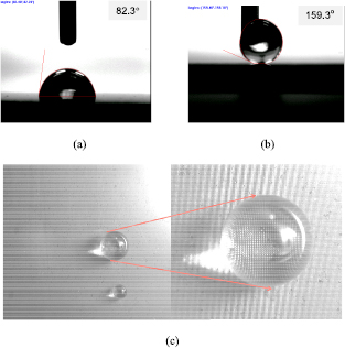
Figure 3. Measured WCA on original Ni (a), laser textured Ni (b), and images of water drop staying on the laser textured Ni surface (c).
Download figure:
Standard image High-resolution imageTo further assess the superhydrophobic behavior of the laser treated Ni surface, the laser treated surface CAH was measured. Figure 4 shows a sequence of the growing and shrinking drops on the laser treated Ni substrate. The water droplet is first put on the sample surface (figure 4(a)). Then, the water droplet volume was gradually increased to wet the surface (figures 4(b)–(d)), and subsequently reduced (figures 4(e)–(g)) until finally the contact between the droplet and the surface was broken. This procedure facilitated the measurements of the WCA hysteresis, defined as the difference between the contact angles of the growing droplet and the shrinking droplet. With the measured advancing contact angle of 159° and receding contact angle of 155°, the CAH for the laser textured Ni substrate surface was less than 5°. Accordingly, this sample surface can be considered superhydrophobic.

Figure 4. Contact angle sequence during the measurement of the CAH on the laser textured Ni surface. The water droplet first put on the sample surface (a), the water droplet volume gradually increases to wet the surface (b)–(d), and the water droplet volume subsequently reduces until it detaches from the surface (e)–(g).
Download figure:
Standard image High-resolution imageFurthermore, with a high speed camera, the water droplet was recorded to bounce up and down when it fell and hit the laser textured Ni surface due to its superhydrophobicity. Figure 5 shows the time-sequence snapshots of a water droplet with a volume of about 3 µl falling onto the laser textured Ni surface. Upon hitting the textured Ni surface, the droplet bounced back and forth more than four times just like a basketball. This further verified the super-hydrophobicity of the laser textured Ni surface.
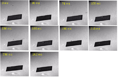
Figure 5. Time sequence snapshots of a water droplet falling on the laser textured Ni surface.
Download figure:
Standard image High-resolution imageBoth the surface topographical structure and the surface chemistry determine the wetting property of a solid surface. Thus, XPS analysis was conducted on the untreated and laser treated Ni surface to investigate the effect of the chemical composition. Figure 6 shows the XPS spectra of the Ni surface before and after laser treatment. The spectra were measured after 60 s of Ar+ ion sputtering to remove the surface contaminants from the ambient atmosphere.
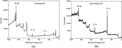
Figure 6. XPS spectra for untreated Ni (a) and laser treated Ni (b).
Download figure:
Standard image High-resolution imageIt was observed that after the laser treatment the relative intensity of the C1s peak had increased much more than that of the untreated sample, which corresponded to an increase in the carbon elemental concentration on the laser textured Ni surface. Table 1 lists the C, O, and Ni elemental concentrations (atom %) on the Ni substrate surface before and after laser treatment. The carbon concentration on the laser treated Ni surface was 81.49%, which was much higher than the carbon concentration of 43.77% on the untreated Ni surface.
Table 1. C, O, and Ni concentrations (atom %) on the substrate surface.
| Untreated Ni | Laser treated Ni | |
|---|---|---|
| C (atom %) | 43.77 | 81.49 |
| O (atom %) | 17.89 | 12.63 |
| Ni (atom %) | 38.34 | 5.87 |
As such, a nonpolar carbon layer was believed to have been formed on the laser treated Ni surface. Just like the mechanism involved in the N2O direct decomposition [32], here we hypothesize that the carbon layer formation was a result of carbon dioxide being decomposed into carbon with the active NiO as a catalyst created by laser irradiation, similar to the active magnetite Fe3O4−δ (0 < δ < 1) created during laser surface treatment of stainless steel [12, 15], which was able to catalyze the dissociate adsorption of carbon dioxide into a carbon layer.
It is known that nickel oxide has the catalytic ability to produce a wide variety of carbon related materials such as carbon vermicules, graphite whiskers, and carbon tubes [33–35]. Figure 7 shows the Ni 2p XPS spectra of the substrate surface before and after laser treatment. It is observed that the Ni 2p3/2 peak for the laser treated Ni surface has an obvious shoulder peak on the higher binding energy (BE) side. In contrast, there is not such a shoulder for the untreated Ni surface. The Ni 2p3/2 peak for the laser treated Ni was deconvolved into two other peaks at BE values of 853.10 and 854.78 eV. The peak at the BE value of about 853.10 eV could be ascribed to the presence of metallic nickel (Ni0), whereas the peak at 854.78 eV could be due to the Ni2+ in the form of NiO [32]. Thus, a Ni0–Ni2+redox couple was present on the surface of the laser treated Ni substrate. However, for the original Ni substrate, at the BE of 852.83 eV, which is due to the presence of metallic nickel (Ni0), the spectra could almost be well fitted with a Gaussian profile, and there was no obvious shoulder peak for the Ni 2p3/2 peak. Figure 8 shows the O1s XPS spectra of the substrate surface before and after laser treatment. The O1s peaks for both the original and laser treated Ni surface were deconvolved into three other peaks at BE values of 529.7, 531.5, and 533.2 eV. The peak positioned at 533.2 eV could be ascribed to oxygen atoms in the adsorbed water molecules [36], the peak at 529.7 eV is from the NiO oxygen atoms [36, 37], and the peak at 531.5 eV could be assigned to oxygen atoms in the hydroxyl groups [38], or adsorption of oxygen-containing species on the sample surface which could be OH− or O− species [39]. It was interesting to observe that in contrary to the spectra of the original sample surface, for the laser treated Ni surface, the relative peak intensity at 531.5 eV was higher than the peak intensity at 529.7 eV; this may indicate that more oxygen-containing species such as O− were generated and adsorbed on the sample surface.
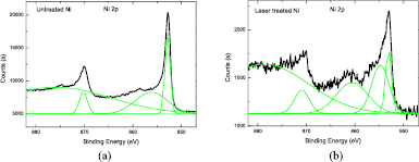
Figure 7. Ni 2p XPS spectra of untreated Ni (a) and laser treated Ni (b).
Download figure:
Standard image High-resolution image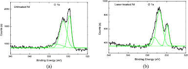
Figure 8. O 1s XPS spectra of untreated Ni (a) and laser treated Ni (b).
Download figure:
Standard image High-resolution imageBased on these XPS spectra characterization results and discussion, the CO2 decomposition on the laser treated Ni substrate surface may involve the following steps [32]: (i) ps laser irradiation induced formation of the catalytic NiO layer; (ii) CO2 adsorption via electron donation from the catalytic NiO surface to the adsorbate; and (iii) the destabilization of C–O bond leading to its scission and the liberation of C and the formation of an adsorbed O− species. Here, we propose that laser beam irradiation might induce more oxygen deficient active Ni oxide based catalyst. When CO2 contacts with oxygen deficient Ni oxide, decomposition of CO2 occurs by the incorporation of oxygen anions in the vacancies of the oxygen deficient Ni oxide (NiO1−δ or Ni2O3−δ (0 < δ < 1)), thereby restoring the deficient Ni oxide to stoichiometric Ni oxide (NiO or Ni2O3). At the same time, electrons are donated from the oxygen deficient Ni oxide to produce carbon or carbon monoxide. The mechanism of CO2 decomposition by the oxygen deficient Ni oxide based catalyst can be expressed with the following chemical equations [40]:

or

This reaction needs to have redox couples on the NiO catalyst surface such as Ni0–Ni2+. As previously discussed, the XPS analysis (figure 7(b)) indicates the presence of Ni0 and Ni2+ species on the surface of the laser treated Ni substrate, suggesting that these two species take part in the CO2 decomposition. In addition, the decomposition of CO2 leads to the formation of carbon and the adsorbed O−species which was verified by the XPS analysis (figures 6 and 8).
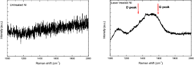
Also, as shown in figure 9, the Raman spectra were measured on the untreated and laser treated Ni substrates to identify the structure of the C after laser treatment. It can be seen that for the untreated Ni, no Raman signal was detected indicating no C layer or Ni oxide on the Ni surface, whereas for the laser treated Ni, a very broad peak was detected which covered the G peak and D peak of the carbon with a broad peak width, indicating that the laser induced C most likely had an amorphous carbon structure [41].
Figure 9. The Raman spectra measured on (a) untreated Ni and (b) laser treated Ni.
Download figure:
Standard image High-resolution image
The CO2 decomposition reaction resulted in the nonpolar amorphous carbon accumulation on the laser treated rough surface with a low surface energy. In combination with the laser treatment induced dual scale hierarchical surface texture (figure 1(c)), a superhydrophobic Ni substrate surface has been achieved, which is comparable to the superhydrophobic lotus leaf.
4. Conclusions
We investigated 1.06 µm ps laser surface texturing of a Ni substrate. A regular 2D array of micro-bumps-based textures superimposed with sub-micro-ripples has been demonstrated. The textured surface displayed superhydrophilicity with almost complete wetting of the structured surface just after laser treatment, then quickly changed to nearly superhydrophobic with a WCA of 140° in less than 1 d, and finally became superhydrophobic with a WCA of more than 150° and a CAH of less than 5°. Through XPS analysis, it can be deduced that the ultra-fast laser beam irradiation induced the NiO catalytic effect. This modified the surface chemistry through decomposing CO2, resulting in carbon formation on the laser treated Ni substrate surface and lowering its surface energy. Together with the laser created dual scale roughness structure, a superhydrophobic Ni substrate surface has been achieved. This surface is comparable to the superhydrophobic lotus leaf. This superhydrophobic surface with lower surface energy has the potential to improve the performance of nickel mold for ease of demolding, which is desirable in the fabrication process.
Acknowledgments
The authors would like to thank Mr BK Lok for his help with CAH measurements. They would also like to thank the Agency for Science, Technology and Research (A*STAR) of Singapore for financial support.