

Abstract
In this paper, we report on a low-cost, environment-friendly and wearable thermal flow sensor, which can be manufactured in-house using pencil graphite as a sensing hot film and biodegradable printing paper as a substrate, without using any toxic solvents or cleanroom facilities. The hot film flow sensor offers excellent performance such as high signal-to-noise ratio ( 40 for an air flow velocity of 1 m s−1), high sensitivity to airflow (53.7 mV(m s−1)−0.8) and outstanding long-term stability (almost no drift in 24 h). The sensor can be comfortably affixed to the philtrum of patients and measures human respiration in realtime. The results indicate that the wearable thermal flow sensors fabricated by this solvent-free and user-friendly method could be employed in human respiratory monitoring.
Export citation and abstract BibTeX RIS
1. Introduction
In the past few decades, the development of MEMS (micro electro-mechanical system) sensors has been directed towards high sensitivity, fast response, miniaturization ability, integration capability and mass production [1, 2]. However, the fabrication of these sensors has widely employed cleanroom facilities, complex and advanced processes such as lithography and metal deposition [3] for the processing of brittle materials, including silicon (Si) [4, 5] and silicon carbide (SiC) [6, 7]. The use of these brittle materials limits applications of such MEMS sensors in human motion detection, wearable therapies and body-attached healthcare services, which typically require outstanding flexibility and stretchability. The fabrication of these sensors has also involved hazardous chemical etchants such as HF and potassium hydroxide (KOH), which contribute to greenhouse gases and lead to various contamination issues. Therefore, there is a strong demand for developing fabrication technologies for flexible sensors, which are cleanroom-free, and friendly for both user and environment.
Recently, the research community has paid great attention to flexible sensors that demonstrate sustainability and flexibility/stretchability for wearable applications such as sleep perception and other healthcare applications [8, 9]. The current strategies for fabricating flexible and wearable sensors have involved the deposition of nanomaterials (e.g. AgNWs, CNTs) on low Young's modulus substrates such as silicone rubbers, plastics and PDMS [10–12]. For example, various conventional MEMS thermal flow sensors [13–19] and wearable flow sensors [20, 21] have been successfully demonstrated, showing relatively high sensitivity and low power consumption. The fabrication of these sensors requires lithography and advanced etching processes, and involves non-biodegradable materials [13–21]. However, these approaches have been associated with numerous toxic chemicals and solutions such as silver nanowire inks [22]. It has also required complex processing of these solutions with dispersion using magnetic stirring or ultrasonication, which makes the fabrication of these flexible sensors more complex and time-consuming. Moreover, the use of polymeric substrates to achieve flexibility can lead to environmental issues because of their non-biodegradable properties. These issues raise the need for exploring alternative green processing of eco-friendly materials for wearable healthcare applications [23].
This emerging demand has led to the rapid development of paper-based electronics, thanks to the various advantages of paper such as low cost, biodegradability, sustainability and flexibility. As such, a proof of concept has been successfully demonstrated with numerous paper-based devices including chemiresistors [24], flexible strain sensors [25–27], temperature sensors [28, 29], flow sensor [30] and transistors [31]. The successful fabrication of these electronic devices indicates a promising future for the next generation of low-carbon-footprint and green wearable sensors using cellulose paper as an eco-friendly and flexible platform.
In this study, we report the solvent-free and cleanroom-free fabrication of a degradable flexible sensor which could be comfortably affixed to the upper lip to noninvasively monitor human respiration in real-time with a high sensitivity. The hot film sensors were constructed using pencil graphite simply drawn on cellulose fiber paper substrate, which can be fabricated in-house without using any toxic chemicals and cleanroom facilities or complex processes. The sensors offer high sensitivity, low power consumption, high signal-to-noise ratio (SNR) and good long-term stability. The results indicate that sensors fabricated by this simple but effective approach can be utilized to produce low-cost, environment-friendly, sustainable, flexible and wearable sensors for noninvasively monitoring human respiration in realtime.
2. Fabrication of graphite-on-paper (GOP) wearable sensors
In order to fabricate a graphite-on-paper (GOP) sensor, a sheet of paper (Staples, A4) was mounted on a movable plate (ProtoMat S42). Then, a graphite trace was created by moving the paper back and forth ten times with a plate default speed of approximately 4 cm s−1 and a constant pressure of 16 MPa at the tip of the pencil. The pressure is tunable using the weight and a cylinder mechanism depicted in figure 1(a). Various pressures were tried, and higher pressures generated graphite trace with lower resistance. Repeated drawing also offered higher electrical conductivity of graphite trace, as shown in figure S1 (supporting information (stacks.iop.org/JPhysD/50/215401/mmedia)). However, higher pressures caused damage to the pencil lead and the paper. Thus, the pressure of 16 MPa was used in this work.
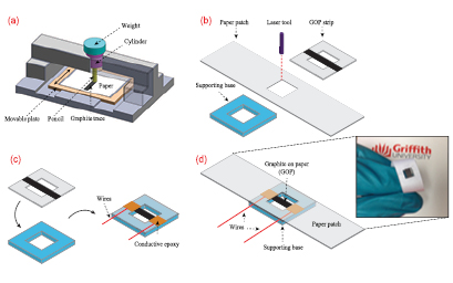
Figure 1. Fabrication of the hot film flow sensor. (a) Schematic sketch of drawing a pencil trace on cellulose paper. (b) Laser cutting of strips, paper patches and supporting base. (c) Assembly of GOP on the supporting base and marking interconnections. (d) Schematic sketch of the sensor structure. The inset shows a photograph of the as-fabricated flow sensor, which indicates its flexibility.
Download figure:
Standard image High-resolution imageThe as-drawn GOP was then cut into GOP strips using a laser cutter (Speedy300TM, Trotecs), as shown in figure 1(b). Paper patches (70 mm × 12 mm) and supporting base (12 mm × 12 mm) were also formed using the laser cutter. In the next step, the GOP strip was assembled with the supporting base using double-sided tape and interconnections were made using highly conductive silver epoxy (186-3616, RS Components) (figure 1(c)). Finally, the paper patch was assembled on the sensor using double-sided tape. Figure 1(d) shows the schematic sketch of the sensor structure. The sensor consists of a GOP hot film, a supporting base and a paper patch for wearing purposes. The GOP film was employed as both heater and resistive sensing element, while the aim of the supporting frame is to avoid resistance change due to the piezoresistive effect [32, 33] under bending or twisting in the wearing process. The inset in figure 1(d) shows a photograph of the as-fabricated flow sensor, indicating its bendability, flexibility and wearability.
3. Results and discussion
3.1. Pencil trace properties
Figure 2(a) shows the scanning electron microscope (SEM) image of the printing paper, which indicates its porous nature. It is also evident that a network of cellulose fibers is randomly oriented, which assists in rubbing off particles from the pencil lead, and retaining them on the paper during the drawing process. Figure 2(b) displays the SEM image of the pencil trace deposited on the paper substrate. To investigate the properties of pencil trace drawn on paper, we performed Raman measurements and observed three sharp peaks at wavenumbers of 1350, 1580 and 2725 cm−1 (figure 2(c) corresponding to the D, G and 2D bands of graphite material [29, 34], respectively. The good quality of graphite material is confirmed because the intensity of G-band (showing a sp2 bonded carbon network) is approximately three times higher than that of D-band (showing the information about defects). As such, the average size L of graphite crystallites is calculated to be approximately 45 nm using the following estimation [34],  , where k is a constant and λ is the laser wavelength;
  is the density ratio of the G-band and D-band. In addition, the main components of pencil lead (5B type) used in this study are graphite crystallites (82 wt
 [35]). These graphite crystallites contribute to the good electrical conductivity of the as-drawn graphite trace. Evidently, figure 2(d) shows a relatively low resistance (10 k
 ) for the 10 mm-length graphite trace. It is also evident that a linear current-voltage relationship was obtained for the pencil trace, indicating an Ohmic characteristic of the resistive film.
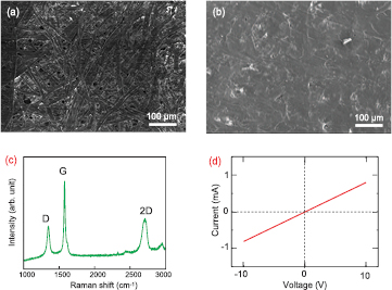
Figure 2. Characteristics of the pencil trace drawn on cellulose paper. (a) SEM image of cellulose paper. (b) SEM image of the pencil trace drawn on paper. (c) Raman spectrum of the pencil trace, showing the characteristics of graphite materials. (d) I–V characteristics of graphite trace.
Download figure:
Standard image High-resolution image3.2. Hot film characterization
Self-heated hot films have previously been proven to be an effective platform for various sensing applications, including Pirani gauges [36], gas sensors [37], and flow sensors [13, 14, 38]. To realize a high sensitivity for such diverse applications, good thermal isolation and temperature uniformity are desired for the hot films. This can be achieved with free-standing and isolated thin films such as bridge or cantilever configurations. Therefore, we constructed the graphite sensing layer on cellulose fiber paper that has a low thermal conductivity and lower heat conduction through mechanical links. Moreover, the nominal resistance of the hot film sensor is approximately 2.1 k , which is suitable for the heating purpose as a hot film. In addition, pencil graphite as a sensing layer would offer high sensitivity, owing to the high temperature coefficient of resistance of graphite [29].
Figure 3(a) shows the temperature distribution around the GOP flow sensor at a supply power of 120 mW taken by an infrared camera (GOBI-1513, Xenics Infrared Solutions) at an ambient temperature of 23 °C. The temperature distributions in horizontal position AA' and vertical position BB' were measured and a high temperature gradient was observed for the hot film (figures 3(b) and (c)). This high temperature gradient indicates that the temperature rise is well-localized on the GOP heater. This is attributed to the fact that power loss due to conduction is small because of the low thermal conductivity of paper [39]. It is also evident that a high temperature of more than 100 °C was achieved for a power consumption of 120 mW. This property confirms that the graphite film can be used as a self-heated element at low power consumption and low supply voltage.
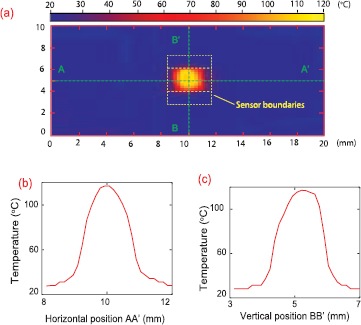
Figure 3. Temperature distribution across the hot-film thermal flow sensor. (a) Thermal image of the sensor under an applied power of 120 mW. (b) Temperature distribution on AA' cross-section (horizontal). (c) Temperature distribution on BB' cross-section (vertical).
Download figure:
Standard image High-resolution image3.3. Performance of hot-film flow sensors
Figure 4(a) shows the working principle of the hot film flow sensor. As such, when a large constant current is applied to the sensor, temperature rise occurs around the graphite film due to the resulting Ohmic loss, and reaches a steady state when the heat loss is equal to the supplied power [40]. Under constant current operation (I = const), the following equation describes the the relationship between the Joule heating power and the power loss due to convective heat transfer in the steady state regime:

where R, A and T are the resistance, the surface area and the temperature of the graphite hot film, respectively; Te is the air temperature and h is the convective heat transfer coefficient. According to the King's law, the convective heat transfer coefficient can be expressed in the following form:

where a, b and n are constants and  is the air velocity. When a flow passes around the film, power loss increases and the temperature of the film decreases. This leads to the increase in electrical resistance of the graphite film, owing to the negative temperature coefficient of resistance of the pencil graphite material [29]. This resistance variation can be obtained by measuring the change of output voltage from the sensor. Making the substitution of equation (2) in equation (1), the output voltage V = IR from the sensor can be determined from the following expression:

where A and B are temperature-dependent coefficients. The relationship between the output voltage difference  and the air velocity can be empirically described as follows [13, 14]:

where α and β are empirical constants. To test the response of the flow sensor to the air flow, we employed a four-point measurement to monitor the resistance change of the sensor (figure S2, supporting information). The flow measurement setup is shown in figure S3 (supporting information). Figure 4(b) shows the response of the sensor to different air flow velocities, under differently applied constant currents. The flow responsivity of the sensor is estimated using differential output voltage [ ], where V and Vo are the output voltages from the sensor at flow velocities of
  and 0, respectively. Based on the different
  V values, the empiric constants α, β and n of equation (4) were estimated to be 226.5, 53.7 and 0.8, respectively. Therefore, the sensitivity of the sensor was calculated to 53.7 mV (m s−1)−0.8 (see table 1).
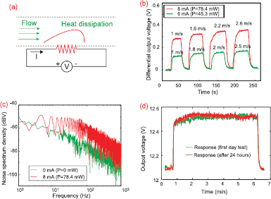
Figure 4. Performance of the hot-film thermal flow sensors. (a) Working principle of the hot film flow sensors. (b) Response of the sensor to different air flow velocities under different applied powers. (c) Noise spectral density of the sensor. (d) Long term stability of the sensor.
Download figure:
Standard image High-resolution imageTable 1. Comparison of performance and sustainability of the flow sensor in this work and literature.
| Material | Sensitivity | Power | Biode. | Solvent | Cleanroom | Cost | References |
|---|---|---|---|---|---|---|---|
| Platinum | 7.98 mV(m s−1)−0.5 | 45.10 mW | No | Yes (KOH) | Yes | High | [13] |
| Platinum | 14.1 mV(m s−1)−0.8 | 20 mW | No | Yes (KOH) | Yes | High | [14] |
| Platinum | 0.7479  (m s−1)−1 (m s−1)−1 |
— | No | Yes (KOH) | Yes | High | [15] |
| Polysilicon | — | — | No | Yes (SF6) | Yes | High | [16] |
| Pt and Au | — | — | No | Yes (SF6) | Yes | High | [17] |
| W/Ti/Pt | 105 μV/(μl/min) | 23.5 mW | No | Yes (HCl) | Yes | High | [18] |
| Silicon | — | 600 mW | No | Yes (KOH) | Yes | High | [19] |
| CNT | 1.208 mV(m s−1)−0.8 | 4.4 mW | Yes | No | Yes | High | [30] |
| Nickel | 50 mV/(l min−1) | — | No | Yes | Yes | High | [20] |
| Platinum | 0.385 V2(m s−1)−0.52 | — | No | Yes | Yes | High | [21] |
| Graphite | 53.7 mV(m s−1)−0.8 | 78.4 mW | Yes | No | No | Low | This work |
It is noteworthy that the differential output voltage increases with increasing air flow velocities due to the increase of heat losses. It is also evident that the higher the supply power or supply current, the higher the differential output voltage at the same air flow velocity. For example, at a flow rate of 1 m s−1,  is approximately 240 mV at a constant current of 8 mA (78.4 mW power consumption), which is at least twice the value for
  at 6 mA (45.3 mW power consumption). Therefore, we could improve the sensitivity of the flow sensor by increasing the supply power.
As a high SNR is desired for the flow sensor, we measured the noise of the sensor. As shown in figure 4(c), the noise density increases with increasing applied power, and decreases with increasing working frequencies. However, the maximum noise level was estimated to be lower than −50 dBV. Since the relationship between the noise power (PdBV) and the noise voltage (Vnoise) can be expressed as  , the corresponding noise voltage was found to be 0.00316 V. Therefore, the minimum SNR of 40 was estimated, which is at least one order of magnitude higher than a standard SNR of a true signal (SNR = 3). In addition, the 63.2
 thermal response time of the sensor was estimated to be 1.4 s (figure S4, supporting information).
When the heating power compensates for the heat loss at the paper-based hot film interfaces, a relatively large temperature of more than 100°C could occur and be maintained for a while. This may lead to the degradation of the hot-film performance. Therefore, it is important to evaluate the long-term repeatability of the sensor response. We measured the response of the flow sensor on different days, showing a good repeatability of the sensor signal (figure 4(d)). This confirms the good long-term stability of the sensor. We also measured the resistance of the sensor under the exposure of a high humidity environment, indicating that drifts in the sensor signal need to be eliminated for accurate monitoring of flow (figure S5, supporting information).
The performance and properties of this thermal flow sensor is compared with the other thermal flow sensors reported on various rigid and plastic substrates as shown in table 1. Being a low cost, solvent-free and cleanroom-free approach, this can be employed in developing disposable flexible and wearable thermal flow sensors.
3.4. Noninvasive respiratory monitoring
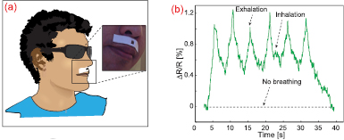
Measuring respiration is an effective approach that has been employed to support therapy for respiratory diseases. However, existing systems have normally exploited nasal cannulas, which include two small pipes to be invasively inserted into the nostrils, leading to uncomfortable breathing for patients. Therefore, there is a great demand to develop wearable flow sensors for noninvasive respiratory monitoring. We demonstrated the feasibility of using the as-fabricated hot film sensor for human respiration by affixing it to the upper lip (philtrum). Figure 5(a) shows that the sensor is flexible and hence wearable, which is casually affixed to the philtrum of a patient without causing any uncomfortable breathing. All experiments regarding measurement of human respiration were performed in compliance with the relevant laws and institutional guidelines and approved by the Human Research Ethics Committee (HREC) of Griffith University.
Figure 5. Demonstration of human respiration monitoring. (a) The photograph showing the wearability of the flow sensor, which can be comfortably affixed to the philtrum. (b) Real-time response of the wearable flow sensor to human breath.
Download figure:
Standard image High-resolution image
Figure 5(b) shows periodic resistance change from the hot film sensor induced by the exhalation and inhalation of breath, with a high SNR. It is evident that exhalation brings a larger resistance change in comparison to inhalation, indicating a larger air flow rate passing over the sensor. The results suggest a strong feasibility of using the lightweight and biodegradable sensor for monitoring respiratory disease, sleep quality and other healthcare applications.
4. Conclusion
In conclusion, the results herein demonstrate extremely low-cost and biodegradable flow sensors using ubiquitous pencil graphite as a hot film sensing layer, which were simply constructed on low-cost, recyclable and biodegradable printing paper using a drawing approach and a subsequent laser cutting method. We successfully demonstrated a GOP-based patch-type devices operating as a sensitive thermal flow sensor which can noninvasively monitor human respiration in real time. The highly sensitive and biodegradable flow sensors fabricated by the cleanroom-free, simple and user-friendly approach indicate that eco-friendly, lightweight and wearable GOP-based devices could be utilised for noninvasively monitoring human respiration.
Acknowledgments
This work was performed in part at the Queensland node of the Australian National Fabrication Facility, a company established under the National Collaborative Research Infrastructure Strategy to provide nano and micro-fabrication facilities for Australia's researchers. This work has been partially supported by Griffith University's New Researcher Grants and Australian Research Council grant LP150100153.