
Abstract
The acceleration of single electrons and electron bunches by focused THz pulse pairs has been investigated by numerical simulations. The effect of the choice of the beam waist radius, the carrier-envelope phase, and the propagation direction of the THz pulses on the energy of the accelerated electrons was investigated. The acceleration of electron bunches from rest up to 150 keV was predicted using single-cycle THz pulses with 1 mJ energy and a central frequency in the 0.1 THz to 3.0 THz range. The post-acceleration of electrons by pairs of focused THz pulses has also been proposed.
Export citation and abstract BibTeX RIS

Content from this work may be used under the terms of the Creative Commons Attribution 3.0 licence. Any further distribution of this work must maintain attribution to the author(s) and the title of the work, journal citation and DOI.
1. Introduction
Conventional particle accelerators, based on radio-frequency fields, are rather complex and costly devices. In search of simpler and more cost effective solutions, laser-driven compact acceleration schemes have been proposed and realized over the past few decades. These setups, utilizing the unprecedented field strength of high-power short laser pulses, can become practical alternatives to hundreds-of-meters long conventional particle accelerators. Laser-driven accelerators include laser-plasma accelerators [1, 2], dielectric laser accelerators [3, 4], and free-space accelerators [5, 6].
With the development of strong-field THz pulse sources over the last decade, a new route has opened up for the efficient acceleration of charged particles. The energy of THz pulses has been increasing by many orders of magnitude, now approaching 1 mJ [7, 8]. Up to 100 MV cm−1 peak electric field has been demonstrated at higher, few tens-of-THz frequencies [9]. Efficient THz generation has been achieved by optical rectification in organic crystals [10, 11], lithium niobate (LN) [12] and semiconductors [13, 14]. THz-driven electron accelerators can offer significant advantages over laser-driven schemes. THz pulses have a wavelength about two orders of magnitude longer than that of visible or near-infrared pulses. This enables a significant increase in both the interaction length and the number of particles, as compared to laser-driven schemes. Furthermore, due to their picosecond-long period, more precise phase synchronization can be achieved between the particles and an accelerating THz field.
In recent years, THz-driven electron manipulation [15, 16], the electron gun [17], dielectric accelerator [18, 19], acceleration in cavity [20], x-ray generation [21, 22] and the linear accelerator [23] have been proposed and simulated. THz-driven electron acceleration in vacuum [24] and in waveguide [25, 26] have been experimentally investigated. High-energy THz sources can also be suitable for post-acceleration and monochromatization of laser-generated protons [27] and for the direct driving of a low-energy proton source in plasma [28].
In this paper, a numerical investigation of electron acceleration and post-acceleration by counter-propagating focused THz pulses is presented. The injection of electrons is accomplished by ionizing atoms in a gas jet with a short laser pulse and by obstructing part of the THz beams in the initial and post-acceleration stages, respectively. The acceleration scheme is introduced in section 2. The acceleration of a single electron and an electron bunch is described in sections 3 and 4, respectively. Post-acceleration is briefly discussed in section 5, followed by the conclusion in section 6.
2. Electron acceleration scheme with focused THz pulses
The schematic view of the initial acceleration arrangement (electron gun) is shown in figure 1(a). Two counter-propagating single-cycle THz pulses create a transient standing wave. Ideally, the two THz pulses have the same waveform and the same polarization direction. In this case, the magnetic fields of the two THz pulses have opposite directions, thereby minimizing magnetic deflection effects on electrons. Electrons are injected by a synchronized short laser pulse which ionizes the atoms in a desired small volume within a gas jet. The generated electrons are then accelerated by the superposition of the electric fields of the two THz pulses (figure 1(b)).
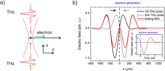
Figure 1. (a) Initial electron acceleration setup with two single-cycle THz pulses propagating in opposite directions. The blue dot indicates the electron injection position. (b) The field of the THz pulses along the x-axis at the optimal birth/arrival time of the electrons.
Download figure:
Standard image High-resolution imageThe effect of the THz pulses on the electrons is determined by the well-known relativistic Lorentz equation

where γ is the relativistic factor, q is the electron charge,  is the velocity of the electrons,
  is the electric field strength and
  is the magnetic induction of the superposed THz pulses. Assuming the polarizations of the THz pulses in the z direction and propagation in the ±x directions, the electric field amplitude is given by:
where r is the radial distance from the propagation axis of the THz beams (x-axis), with the foci located at x = 0,  is the wave number,
  is the wavelength of the THz pulse,
  is the radius at which the field amplitudes fall to 1/e of their axial values at the plane y-z along the beam,
  is the waist radius,
  is the wavefront radius of curvature at x,
  is the Gouy phase and
  is the phase. A Gaussian profile,
  is taken for the THz pulse, where
  is the FWHM pulse duration.
The values of the parameters assumed in the simulations for the THz pulses are listed in table 1. THz pulses with different central frequencies of 0.14 THz, 0.3 THz, 0.7 THz, and 3.0 THz were used in the calculations. The parameters of THz pulses with 0.3 THz central frequency were based on a recent numerical investigation of a hybrid-type LN THz pulse source [29]. At the other frequencies, the simulations were based on published experimental data of THz sources with the highest energies using LN [12], semiconductor ZnTe [13], and organic DSTMS [8, 11] generator crystals. The different reported waveforms, pulse energies, and focused spot sizes were used for most of the calculations. In all cases, a further increase in THz pulse energy can be expected (e.g. by using a large-area LN with uniform crystal length [29] in combination with cryogenic cooling [30], or via infrared-pumped semiconductor contact-grating technology [31]). Therefore, the calculations were also extended to higher, 1 mJ THz pulse energies, assuming diffraction-limited focusing to  (the corresponding parameter values are parentheses in table 1).
Table 1. The data of the experimentally generated maximum energy THz pulses at 0.14 THz, 0.7 THz and 3 THz frequencies and numerical investigation of a hybrid-type terahertz pulse source at 0.3 THz frequency used in simulations (* extrapolated values for 1 mJ energy).
| Parameter | LiNbO3 [12] | LiNbO3 [29] | ZnTe [13] | DSTMS [8, 11] |
|---|---|---|---|---|
| Mean frequency | 0.14 THz | 0.3 THz | 0.7 THz | 3.0 THz |
Mean wavelength ( ) ) |
2.143 mm | 1 mm | 0.429 mm | 0.1 mm |
Electric field ( ) ) |
1.05–1.74* MV cm−1 | 0.40–5.21* MV cm−1 | 1.00–16.9* MV cm−1 | 48.4–113* MV cm−1 |
Beam waist ( ) ) |
2.143 mm*–2.4 mm | 1 mm*–2.5 mm | 0.429 mm*–1 mm | 0.1 mm*–0.221 mm |
Pulse duration ( ) ) |
3.21 ps | 1.66 ps | 0.85 ps | 0.36 ps |
Phase ( ) ) |
1.54 rad | 0 | 1.54 rad | 2.3 rad |
| Energy | 436 μJ | 337 μJ | 14 μJ | 900 μJ |
3. Acceleration of a single electron
The energy change of an electron during the acceleration lasts as long as the THz pulse affects the particle; therefore, the parameters of the THz pulses determine the efficiency of the acceleration. In this section the final energy of a single electron accelerated in the setup shown in figure 1(a) is investigated. We optimized the beam waist, the carrier-envelope phase (CEP) and the tilt angle of the propagation direction of the THz pulses (see also figure 4(a) below). For the sake of simplicity, the ionization volume has been assumed to be centered at the THz focus. Here, we note that optimizing the position of the ionization volume at the beam waist has led only to a minor off-center shift of about 10 μm. The arrival time of the injection laser pulse has been synchronized to the zero-crossing of the THz field preceding the dominant half cycle (figure 1(b)) [23].
3.1. THz beam waist
In order to reduce the decelerating effect of the positive part of the THz pulse (figure 1(b)), we examined the optimal choice of the  intensity beam waist radius (
 ) on the final kinetic energy of the initially standing electrons (
 keV at
  position) in the cases of the THz sources represented in table 1. The kinetic energy of the electron during the interaction with two THz pulses propagating perpendicularly to the electron path is shown in figure 2. It can be seen that the highest electron energies can be achieved when the beam waist radius is equal to the wavelength in each case. An acceleration of 13.2 keV and 16 keV can be achieved by pulses generated in lithium niobate with 0.14 THz (a) and 0.3 THz (b) mean frequencies, respectively. The small final kinetic electron energy of 1 keV in the case of the ZnTe THz source (c) is due to the small THz pulse energies of only about 3% of those generated in LiNbO3. With the development of technology they can also be competitive in effective electron acceleration. Final kinetic energies of more than 100 keV can be reached using the pulses generated by optical rectification in DSTMS (d).

Figure 2. The time evolution of the energy of a single, initially standing electron, accelerated by THz pulse pairs propagating perpendicularly to the electron path. The assumed THz pulse energies were the highest experimentally generated or numerically predicted ones, as given in table 1.
Download figure:
Standard image High-resolution image3.2. CEP of the THz pulses
Increased accelerated electron energies can be expected by using more energetic THz pulses. By extrapolating the present development of THz source technology, one can expect that in case of all three considered materials the THz pulse energies will exceed 1 mJ. Therefore, in all further calculations we assumed 1 mJ for the energy of each individual THz pulse. This has been achieved by increasing the electric field, but keeping the waveforms (except the CEP). In addition, the beam was assumed to be focused to a spot size equal to the wavelength, as discussed in section 3.1 (see also table 1). Other quantities are the same as in the previous case.
THz CEP can eventually be tuned in experiments. Therefore, we studied the accelerated electron energy as a function of the initial phase ( ) using parameters of table 1 (in case of 1 mJ). The result is shown in figure 3. According to our calculation, the highest energy can be achieved at
  for our THz pulses with 0.14 THz, 0.3 THz, and 0.7 THz mean frequencies and the energy increase can be as large as 55%, 35%, and 15%, respectively. Thus, it is important to pay particular attention to CEP optimization in order to achieve more energy.
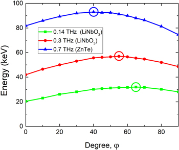
Figure 3. Electron energy as a function of the initial phase ( ) of the THz pulses. A THz pulse energy of 1 mJ has been assumed in each case.
Download figure:
Standard image High-resolution image3.3. Propagation direction of the THz pulses
There is a potential to extend the interaction length between the electron and the accelerating part of the THz pulse and approach the velocity matching condition between the THz pulse and the electron by tilting the THz beam propagation direction by an angle θ (figure 4(a)). For tilted THz beams, the longitudinal (accelerating) component of the THz pulse is decreased, but the interaction length between the electron and the accelerating part of the THz pulse is extended, potentially resulting in a higher electron energy. The calculated final kinetic energies as functions of the tilt angle are shown in figure 4(b). The optimum tilt angles and achieved electron energies are summarized in table 2 for the different types of THz source with 1 mJ pulse energies considered here. In case of the DSTMS source with 3 THz central frequency and the highest accelerated electron energy, an energy gain of 17% can be achieved for the 20° optimal tilt angle, as compared to the untilted (θ = 0°) case. The increased electron energy reaches about 150 keV. At still higher electron energies, one can expect an even larger energy gain at larger optimal tilt angles.
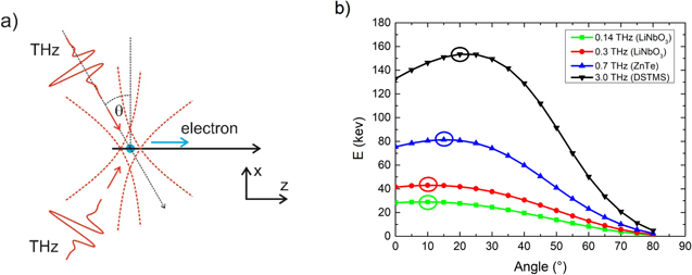
Figure 4. (a) Electron acceleration setup with two single-cycle THz pulses propagating in opposite directions at a beam tilt angle  (b) The final kinetic energies of the electron in case of different
  angles. A THz pulse energy of 1 mJ has been assumed in each case.
Download figure:
Standard image High-resolution imageTable 2.
Final energies of electrons accelerated by THz pulses with 1 mJ energies focused to spot sizes 
| Frequency | Electric field of the THz pulses | Tilt angle ( ) ) |
Final electron energy |
|---|---|---|---|
| 0.14 THz | 1.74 MV cm−1 | 10° | 29.0 keV |
| 0.3 THz | 5.21 MV cm−1 | 10° | 43.4 keV |
| 0.7 THz | 16.9 MV cm−1 | 15° | 81.4 keV |
| 3.0 THz | 113 MV cm−1 | 20° | 153 keV |
4. Acceleration of an electron bunch
Simulations were carried out with realistic electron bunches as well. The scheme of the setup is similar to figure 4(a), however not a single electron is considered. It is supposed that a THz pulse pair is focused on a gas jet, where the electrons are generated. A high-power fourth harmonic beam of 1 μm wavelength is focused on the gas jet  [32], where it ionizes the krypton molecules (4th harmonic and three photon absorption), and electron bunch with 0.5 eV average energies are generated. A laser-ionized gas jet can become an ideal electron source because it enables control of both the charge and the electron bunch size, and a controlled injection of the electrons into the counter-propagating THz beams. Furthermore, it allows the tilted propagation setup, contrary to other sources that do not allow it (for example, photocathodes). Calculations were performed with different ionized region sizes in the gas jet to define the optimal value. The distribution of electrons was Gaussian in the initial case and the total charge was 1 pC (electron and krypton ion, respectively). The THz pulses propagate through the gas jet with an optimal angle (according to figure 4(b)) and perfect synchronization, and accelerate the electrons. The THz pulses were considered to be generated in four different sources, with pulse energies of 1 mJ. The pulse parameters were taken from table 1.
The numerical simulations were performed using a general particle tracer (GPT) and a self-developed program code, which accounts for the space charge effect. The results are shown in figure 5. In our calculations, the energy spread of accelerated electrons was investigated for different sizes of electron bunch. According to our calculation 70 μm, 40 μm, 20 μm and 5 μm (σ) are the optimal bunch sizes for 0.14, 0.3, 0.7 and 3.0 THz mean frequencies, respectively. We have to note that for larger ionizing laser beam waist the initial electron beam size will be larger, too. This causes some limitations to the feasibility of the setup for short wavelength (for example DSTMS source). In cases where the size of THz mean wavelength is almost the same as the bunch size, the energy spread is larger because the electrons situated at different parts of the bunch feel different accelerating fields of the THz pulse. Furthermore, in case of reduction of bunch size, the influence of space charge is larger (for constant bunch charge). Because of the higher space charge, the energy spread is also higher. Our calculations show that the optimal initial bunch size is larger in the case of the THz wavelength is larger. According to our calculations with THz sources of 0.14, 0.3, 0.7 and 3.0 THz mean frequencies, 29.0 keV, 43.4 keV, 81.4 keV and 153 keV peak electron energy can be achieved, respectively. The energy spread (ΔE/E) values are 4, 6, 9.5 and 15%, at the optimal sizes, respectively. This way electron bunches can be created, which can be used in chemical and biological research.

Figure 5. The energy spectra of electron bunches, accelerated by the THz pulse pairs, with 1 mJ energies per pulse, propagating with optimal angle to the electron path.
Download figure:
Standard image High-resolution image5. Post-acceleration of a single electron
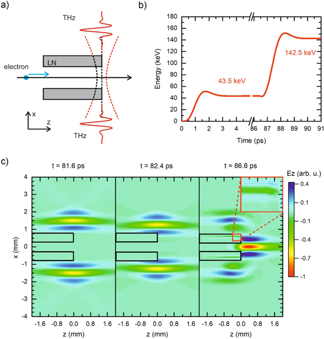
Post-acceleration of accelerated electrons is also feasible by focusing further THz pulses along the path of the electrons with proper synchronization, hence a multi-stage acceleration structure can be realized. In the double-stage acceleration setup the electrons accelerated by a first THz pulse pair (figure 1(a)) are further accelerated by a second pulse pair comprising the 2nd acceleration stage. In this case, half of the THz beam is retarded by LiNbO3 (LN) plates (figure 6(a)) in order to eliminate the decelerating effect of the THz beam until the electron arrives at the beam axis. Therefore, the same synchronization between the THz pulses and electron bunch is accomplished as described in section 2. The electron propagates 1 cm from the gas jet, where the 2nd THz pair accelerates it. The width of LN is 2000–500 μm (in z-x direction, respectively). The THz pulses were focused to the path of the electron beam, to the end of the LN crystals (see figures 6(a), (c)). One half of the THz beam goes through the LN, where its velocity and wavelength is decreased (figure 6(c)). The other half of the THz beam can still propagate through the vacuum, create a standing wave in the axis, and let the perfect synchronization with the pre-accelerated electrons. This separation is shown in figure 6(c) at three different time steps (before the THz reaches the LN, at that point when it reaches, and that point when the synchronization is perfect). At that time, when the injection is perfect, the electric field inside the gap almost disappears. The field evolution was calculated with FDTD numerical code.
Figure 6. Electron post-acceleration setup (a), the energy evolution energy of the two staged accelerated electrons with LN plates in the THz beam path (b), the THz pulse evolution at different time points (c).
Download figure:
Standard image High-resolution image
In the calculations 1 mJ THz pulse energies were considered, the frequency of the pulses was 0.3 THz, the beam waist was equal to the wavelength. In the calculation, we used the pre-accelerated electron from the first stage, and we post-accelerated it. The results obtained with this structure are summarized in figure 6(b). After this stage, the electrons are accelerated to 143 keV energy. We note that when the same THz pulses are applied, higher energy gain can be achieved in the post-acceleration stage than in the first acceleration stage.
6. Conclusion
Electron acceleration to relativistic energies by counter-propagating focused THz pulses was proposed and numerically investigated. Investigations were performed at different THz frequencies based on experimentally achieved or numerically calculated THz pulse parameters. The acceleration rate depends on the phase of THz pulses and on the angle between the propagation direction of the electrons and the THz pulses. The optimal THz propagation angle is higher at higher electron velocity. Final electron energies of 150 keV can be achieved by the proposed acceleration setup in case of electron bunches 20 μm using THz pulses with 1 mJ energies. In the case of post-acceleration, the slowing impact of the positive part of the THz pulse shape can be reduced by placing a dielectric material (for example LiNbO3) in the path of the pulse propagation, delaying half of the THz beam.
Acknowledgments
The project has been supported by the European Union, co-financed by the European Social Fund Grant no.: EFOP-3.6.1.-16-2016-00004 entitled by Comprehensive Development for Implementing Smart Specialization Strategies at the University of Pécs; EFOP-3.6.2-16-2017-00005 entitled by Ultrafast physical processes in atoms, molecules, nanostructures and biology structures. The project has been supported by Hungarian Scientific Research Fund (OTKA) (125808). The present scientific contribution is dedicated to the 650th anniversary of the foundation of the University of Pécs, Hungary.