

Abstract
An electrostatically actuated all-metal microelectromechanical systems (MEMS) Pirani gauge with a tunable dynamic range is proposed. Contrary to the conventional fixed gap Pirani gauges, an electrostatic mechanism is employed to tune the gaseous conduction gap. Due to the electrostatic force between the heating element and heat sink, this tuning results in shifting the transition pressure to a higher pressure. As a result, the operating range of the Pirani gauge can be tuned depending on the magnitude of the actuation voltage. Theoretical estimation of the transition pressure corresponding to different gaseous conduction gaps is also presented. Depending on the available margin of gap tuning, the electromechanical and electrothermal analyses are carried out in COMSOL Multiphysics. The analytical approach is validated by experimentally characterizing the fabricated device. The experimentally tested device with the proposed actuation mechanism shows an 11.2 dB increase in dynamic range in comparison to the conventional design. In a complementary metal-oxide-semiconductor (CMOS)-compatible fabrication process flow, the proposed gauge can be used to monitor vacuum from 40 Pa to 5 × 10⁵ Pa with the electrostatic actuation.
Export citation and abstract BibTeX RIS

Original content from this work may be used under the terms of the Creative Commons Attribution 4.0 licence. Any further distribution of this work must maintain attribution to the author(s) and the title of the work, journal citation and DOI.
1. Introduction
Stringent packaging requirements of microelectromechanical systems (MEMS) are a key hurdle in realizing reliable and cost-effective microsensors. This can be related to vacuum levels down to 10−3 m bar (0.1 Pa) or a high surface-to-volume ratio in a hermetically sealed MEMS device [1]. The development of wafer bonding techniques like anodic bonding, glass-frit bonding, eutectic bonding, and adhesive bonding paves the way for vacuum sealing [2, 3]. However, the permeation rate for most of the packages varies from 10−18 cm3 sec−1 to 10−10 cm3 sec−1 [2]. Given this, the characterization and monitoring of a hermetically sealed MEMS device are crucial as the device output may vary with varying ambient.
Helium leak tests and Q-factor extraction techniques are employed to determine the pressure in micro-cavities [4–6]. However, their use is limited owing to the complexity and expensive procedures [6]. More recently, micromachined Pirani gauges have been integrated with microsensors for fast, affordable, and accurate hermetic monitoring [7]. Pirani gauges are electrothermally driven devices that operate on the pressure-reliant thermal conduction of gas. A micromachined heating element is Joule-heated and the resistance variation is measured across the two ends. At thermal equilibrium, the average temperature depends on the pressure in the micro-cavity and hence, the output resistance is varied.
Since its invention, the quest for wider dynamic range, power efficiency, and improved sensitivity has been active [8–15]. Different approaches based on structural and dimensional optimizations were proposed for improving the gauge performance [9]. The lower vacuum detection limit of a typical Pirani gauge depends on the ratio of gaseous conduction to solid conduction [10]. Lowering the solid conduction increases the gaseous conduction regime thereby extending the lower detection range. Also, materials with lower thermal conductivities materials were used to further reduce the solid conduction [6]. Lai et al presented a fusion study by integrating two Pirani gauges with different lengths [11]. The fusion of two different gauges generated two sensitivity peaks thereby increasing the overall dynamic range. However, the overall die area and cost of implementation were compromised. To extend the high-pressure range, multiple heat-sink-based structures were proposed and the gaseous conduction gap was narrowed [12]. Narrowing the suspended gap itself poses several constraints owing to mechanical failures. As the gap sizes shrink, the fabrication tolerances become stricter, and the likelihood of stiction due to the van der Waals force increases during the releasing step. Furthermore [13], characterized the complementary metal-oxide-semiconductor (CMOS) readout-based transient response to exploit the gauge performance beyond atmospheric pressure. While the series microbridge proposed in [14] extended the dynamic range in the high-pressure regime, the lower detection was limited to 10 kPa. A capping wafer was introduced to further improve the gaseous conduction which ultimately increased the dynamic range [15]. Nevertheless, the reported implementations focused on extending either the lower vacuum regime or high vacuum regime, and the full-scale range of the gauge remains narrow. Apart from these, a highly miniaturized graphene microbridge-based Pirani gauge was reported [16]. Although the gauge is highly miniaturized, the detection range from 100 Pa to 105 Pa was very narrow.
In this paper, we present an all-metal MEMS Pirani gauge with a tunable dynamic range. Contrary to the conventional fixed-gap Pirani gauges where design and operation parameters are fixed, electrostatic actuation is coupled with the electrothermal operation to realize the gap-tunable MEMS Pirani gauge. The idea is realized by constructing an actuation electrode below the heating element to tune the suspended gap. Hence, the limitations of a narrow operating region can be overcome. In consideration of the precise displacement of the microbeam, molybdenum is chosen as the structural material from the class of refractory metals [17]. From the electrostatic driving perspective, Molybdenum is known for its (1) high strength and stiffness, (2) low wear-out over cycles, and (3) excellent oxidization resistance and thermal stability [18]. It can withstand the mechanical forces and stresses associated with electrostatic actuation, reducing the risk of structural failure. Further, Molybdenum is verified to be stable up to 20 billion cycles without failure [19] thereby exhibiting high reliability and longer lifetime. The conceptual schematic of the proposed tunable gauge with different states of operation and dimensional specifications is illustrated in figure 1. An electrostatic force is generated between the heating element and the actuation electrode by applying a voltage bias ( ). As a result, the gap between the heating element and heat sink can be varied, hence the dynamic range can be tuned. The overall operation of the device is segregated into three states i.e., State A, State B, and State C. In State A, no actuation voltage is applied and hence, the gap between the heating element and heat sink is fixed. The gauge works as a conventional one. In State B, an actuation voltage less than the pull-in voltage (
 ) is applied. This state corresponds to a tunable range depending on the magnitude of the actuation voltage. In State C, an actuation voltage greater than the pull-in voltage is applied and the beam snaps down to the substrate. This state is referred to as a forbidden state. An additional sense electrode is constructed to characterize the pull-in which is biased at very low voltage i.e., ∼0.1 V.
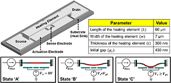
Figure 1. Conceptual schematic of tunable MEMS Pirani gauge showing different states of operation. (a) Initial state (State 'A') of the device with  . (b) Tunable state (State 'B') with actuation voltage
  . (c) Forbidden state (State 'C') with
  .
.
Download figure:
Standard image High-resolution image2. Methods and experiment
A typical Pirani gauge is a simple heater placed in the gaseous ambience to monitor its pressure. The thermal conductivity of the ambient gas varies with the pressure and induces a pressure-dependent heater temperature or heating power. The pressure-dependent thermal conductivity of a gas is given as:
where  = 0.0284 W (m K)−1 is the continuum limit of thermal conductivity of air,
  is the pressure in Pascals (Pa), and
  is the transition pressure in Pa [20]. The transition pressure is a critical design parameter that delineates the transition from the operational regime of a Pirani gauge to a continuum regime where the gauge loses its sensitivity to pressure variations. Equation (1) shows that the gauge characteristics, including the sensing range and dynamic range, are scaled by the transition pressure. For a gauge with a constant heat conduction gap i.e., with a fixed gap between the heating element and the substrate,
  is given by:
where  is the reference temperature in Kelvin and
  is the effective heat conduction gap in metres [21]. Theoretical estimation of
  as a function of
  based on equation (2) is given in figure 2. It can be seen that the transition pressure scales inversely with the gap and changes from approximately 2 × 10⁴ Pa to 2 × 10⁵ Pa for a gap variation from 1 μm to 100 nm respectively.
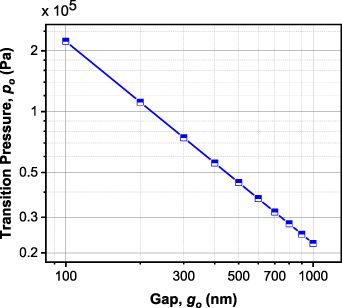
Figure 2. Theoretical estimation of transition pressure with gap variation between the heating element and heat sink.
Download figure:
Standard image High-resolution imageIn the proposed tunable Pirani gauge, the application of the tunable voltage ( ) deforms the clamped–clamped beam. Thus, the heat conduction gap is no longer constant. We define an effective tuned gap
  as,
as,
where  is the displacement of the actuated heating element for a given
  and
and  is the length of the heating element. Thus, the transition pressure for a deformed heating element can be modified as,
It is noted that the beam deformation  can be caused by a number of mechanisms, including the applied electrostatic force, the residual stress accumulated in the fabrication process, and the thermal stress due to the Joule heating power.
2.1. CMOS-compatible fabrication process flow
The fabrication of the proposed CMOS-compatible tunable MEMS Pirani gauge is given in figures 3(a)–(g). Firstly, Si (100) is taken as a starting substrate. Then, 150 nm of Al2O3 is deposited over the bare Si substrate using sputtering to create an insulating layer. A thermal annealing step is performed at 300 °C to minimize the oxygen deficiency and improve the crystallinity of the insulating layer. Next, 50 nm of molybdenum is sputtered and patterned to form the actuation electrodes. Next, 430 nm of SiO2 is sputter deposited to serve as a sacrificial layer. The thickness of SiO2 defines the initial gap between the heating element and substrate (heat sink). The deposited SiO2 is now patterned and etched in the anchor areas using buffered hydrofluoric acid. A 300 nm of molybdenum is now deposited using sputtering and patterned to form the heating element. Lastly, the heating element is suspended using vapor hydrofluoric acid to prevent stiction. The scanning electron microscope (SEM) image of the fabricated device is shown in figure 3(h) and the zoomed-in image at the center region is shown in figure 3(i). Further, the suspended gap (labeled in red and tilt-compensated) in the SEM image matches the designed gap value indicating negligible residual stress.
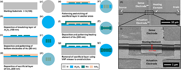
Figure 3. The CMOS-compatible three-mask fabrication process of the proposed Pirani gauge showing the cross-sectional view (a)–(g) along with the top view (a)'–(g)'. (h) Scanning electron microscope (SEM) image of the fabricated device highlighting different electrodes and zoomed-in area. (i) Zoomed-in view at the center of the heating element.
Download figure:
Standard image High-resolution image3. Results and discussion
3.1. FEM analysis of temperature profile and thermal stress
The electrothermal analysis of the structure is carried out in COMSOL Multiphysics using the Joule heating and thermal expansion module. A fixed constraint is applied to the anchor regions and the substrate is kept at  . A sweep of the bias current (
 ) up to 8 mA is applied across the drain and source to find the maximum temperature, as shown in figure 4. The analysis is done at 10 Pa i.e., in the scenario where the heat loss is minimal and temperature change is maximum in a high vacuum regime. This is due to the lesser number of gas molecules available for gaseous conduction and therefore, the
  is maximum. From the temperature increase of ∼103 °C at the center of the heating element for an
  = 6 mA, this
  value is finalized for further analysis. The maximum temperature increase of the gauge is limited to ∼103 °C to limit the thermal interaction with onboard electronics and prevent the oxidization of molybdenum in the long run. Figure 5 shows the maximum temperature of the heating element and associated maximum thermal stress corresponding to different pressure conditions from 10 Pa to 106 Pa. The inset shows the temperature distribution and thermal stress distribution at 10 Pa. The maximum compressive thermal stress along the beam is around −150 MPa at 10 Pa and this value is comparable to the reported values of residual stress in a clamped–clamped molybdenum beam [22–24]. Hence, the effect of thermal stress is not significant. However, the obtained thermal stress results are incorporated in the subsequent analysis to mimic the practical scenario.
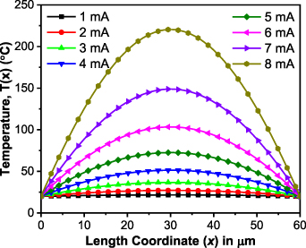
Figure 4. Temperature profile of the heating element for different values of  at 10 Pa.
Download figure:
Standard image High-resolution image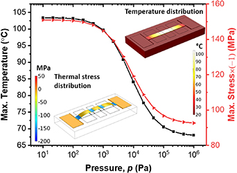
Figure 5. Maximum temperature and maximum stress at 6 mA. Insets show the temperature distribution and thermal stress distribution at 10 Pa.
Download figure:
Standard image High-resolution image3.2. Measurement setup and electrothermal operation
The experimental setup for the characterization of the tunable MEMS Pirani gauge is shown in figure 6. The device under test is placed in a vacuum-controlled probe station (Lakeshore Cryotronics) equipped with a pumping unit, a reference Pirani gauge, and a vent valve for controlling the chamber pressure. The probe arms are connected to the parameter analyzer (Keithley 4200_A SCS) for electrical biasing and measurements. A current bias of 6 mA is injected from the source to drain to check the pressure-dependent voltage response in State A i.e.  . The measurement readings are taken for the entire pressure range of 10 Pa to 106 Pa covering three steps per decade. At thermal equilibrium, the pressure-dependent voltage response
  of the Pirani gauge in State A is given by:

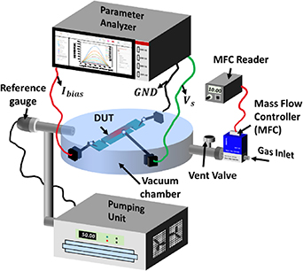
Figure 6. Characterization setup for the proposed gap tunable gauge.
Download figure:
Standard image High-resolution imagewhere  is the nominal resistance at the reference temperature and pressure,
  = 0.45%/K is the temperature coefficient of resistance of the molybdenum heating element [25],
  is the pressure-dependent average rise in temperature of the heater. Figure 7 shows the output voltage
  variations over a pressure range of 10 Pa to 106 Pa in State A (
 ). The solid line represents the simulated curve, and the dots represent the experimental data. A maximum error of 0.7% between simulated and experimental data is observed for the tested device in State A. The inset shows the variation associated with the measurement data (3 datasets) and a maximum variation of 5.98 × 10⁻⁵ V is observed for the tested device. Furthermore, the total input power
  is given by [12]:

Figure 7. Measured voltage variations in State A ( = 0 V) at an
  = 6 mA. The inset shows the error corresponding to each data point over the entire pressure range.
Download figure:
Standard image High-resolution imagewhere  and
and  are the heat losses due to solid conduction and gaseous conduction respectively. This can be rewritten as:
where  =
=  ,
,  =
=  ,
,  is the output resistance for a typical
  . The accuracy of the gauge is determined by curve fitting based on equation (7) where
  ,
,  , and
, and  are the fitting parameters. It can be noted that the simulation curve is not used for calculating the accuracy owing to variations in material properties and geometrical parameters in the fabricated device. Hence, the analytical model (equations (6) and (7)) is used for curve fitting. The blue dashed line in figure 7 shows the fitted curve and the fitted parameters are given in table 1. The fitted parameters are in proximity with the measured data and an accuracy of 3% full-scale is obtained for the proposed gauge in State 'A'.
Table 1. Curve fitting parameters.
| Parameter | State 'A' | State 'B' |
|---|---|---|

| 5.55 × 10⁻⁵ W (m K)−1 | 5.54 × 10⁻⁵ W (m K)−1 |

| 3.63 × 10⁻⁵ W K−1 | 4.09 × 10⁻⁵ W K−1 |

| 5.36 × 10⁴ Pa | 8.54 × 10⁴ Pa |
3.3. Experimental pull-in characteristics
The maximum tuning voltage of the electrostatically actuated fixed-fixed beam that can be applied between the heating element and actuation pad is the pull-in voltage  . However, the conventional simple pull-in voltage equation can not be applied to the proposed gauge because (1) the sensor has a clamped-clamped structure, and (2) the residual stress and thermal stress change the stiffness of the structure. Since the proposed design involves coupled electrothermal operation, the actuation and tuning characteristics of the proposed gauge are investigated by experimentally characterizing the
  .
.
The  is characterized by simultaneously applying the actuation voltage (0 <
  < 30) at the actuation electrode and a current of 6 mA between the source and drain. The current
  readings are recorded at the sense electrode biased at 0.1 V. The analysis is shown in figure 8. An instantaneous increase in current is observed at ∼14.8 V and the current between the heating element and sense electrode rises to the set current limit. This indicates the required
  = 14.8 V for the gauge to enter State 'C'. A driving voltage
  = 13.8 V is finalized for actuating the heating element and gap tuning for further analysis.
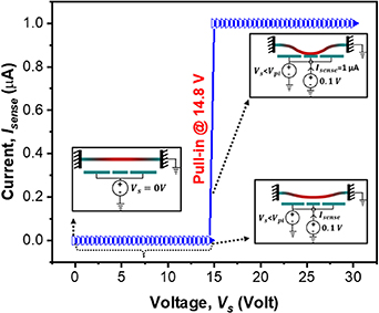
Figure 8. Experimentally characterized pull-in characteristics of the fabricated device showing different regions of operation.
Download figure:
Standard image High-resolution image3.4. Pressure-dependent tunable gauge response
Initially, FEM analysis is conducted in COMSOL Multiphysics for the structural deformation for a given  using the electromechanics module. A 3D geometry is constructed as per the dimensional specifications given in figure 1 and boundary conditions are applied to incorporate the effect of thermal stress due to the Joule heating power. The deformation profiles
  of the actuated beam corresponding to different pressures at
  are shown in figure 9. A maximum displacement of ∼159 nm is observed at 106 Pa at the center of the beam. The effective gap
  can be quantified by averaging these curves according to equation (3) and plotted in figure 10, showing a range of 420 nm to 350 nm. Now the pressure-dependent tunable gauge voltage response is simulated by using the constant effective gap i.e.,
  and the result is plotted in figure 11 (black solid line).
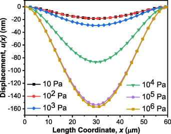
Figure 9. Displacement profile of the heating element at  = 13.8 V.
Download figure:
Standard image High-resolution image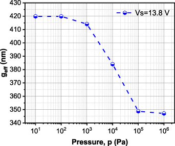
Figure 10. Effective gap ( ) corresponding to different pressures.
Download figure:
Standard image High-resolution image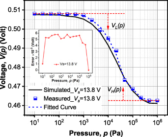
Figure 11. Voltage variations in State B ( = 13.8 V) at an
  = 6 mA. The inset shows the error corresponding to each data point over the entire pressure range.
Download figure:
Standard image High-resolution imageIn experiments, the electrostatic operation is coupled with the electrothermal operation to extract the pressure-dependent gauge response of the fabricated device. A current bias of 6 mA is injected from the source to drain while simultaneously probing the actuation pad. The readings are taken for an entire pressure range of 10 Pa to 106 Pa covering three steps per decade. Blue dots in figure 11 show the output voltage  variations over a pressure range of 10 Pa to 106 Pa with coupled electrostatic actuation i.e. State B with
  = 13.8 V. The inset shows the variation associated with the measurement data (3 datasets) and a maximum error of 5.77 × 10⁻⁵ V is observed for the tested device. Experimental data points are in line with the simulated response with a maximum error of 0.6%. Furthermore, the accuracy of the gauge is determined by curve fitting based on the equation (7) where
  ,
,  , and
, and  are the fitting parameters. The fitted parameters are in proximity with the measured data and an accuracy of 5% is obtained for the proposed gauge in State 'B'. The blue dashed line in figure 11 shows the fitted curve and the fitted parameters are given in table 1. Also, the value of
  increases which is evident since the tuning results in shifting the transition pressure to a higher value.
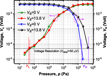
As indicated in figure 11, the gauge response saturates at both high-pressure and low-pressure regimes. Therefore, the detection limits at these regimes and thus the full-scale measurement range are determined by the voltage measurement resolution  ) of the readout/measuring instrument where the gauge sensitivity is diminished. The differences between the measured gauge output voltage
  and the saturation voltage at low pressure (10 Pa) and high pressure (106 Pa) are defined as,


where  is the voltage between the source and drain at a given pressure. When
  and
and  are lower than the voltage resolution
  , the pressure variation is non-resolvable. Thus, the lower detection limit (
 ) and upper detection limit (
 ) of the gauge are defined such that
  <
<  and
and  <
<  . The corresponding characteristics are given in figure 12. The voltage resolution in the current setup is
  = 50 μV. Thus, the device in State A (
 = 0) offers a
  down to 50 Pa and
  up to 1.74 × 10⁵ Pa. Similarly, the device in State B (
 = 13.8 V) offers a
  down to 40 Pa and
  up to 5 × 10⁵ Pa. Further, the full-scale dynamic range (
 ) of measurable vacuum is given by:
The dynamic range in State A is 70.8 dB, which extends up to 82 dB in State B. This indicates that the coupled electrostatic actuation mechanism can significantly improve the dynamic range without compromising the die area.
Figure 12. Output voltage characteristics of the proposed all-metal tunable MEMS Pirani gauge.
Download figure:
Standard image High-resolution image
Although additional biasing is required for the tunable operation, the given mechanism only requires a high DC voltage for electrostatic actuation and no driving current. Hence, the high DC voltage can be accessed through some common approaches like voltage multipliers or DC–DC converters. There will be negligible power consumption in addition to Joule heating power due to the leakage current between the sensing element and the actuation electrode. Qualitatively, the proposed gauge is already operated at the upper limit for this particular  . Further, the tuned margin (82 dB−70.8 dB = 11.2 dB) can be increased by increasing the
  as it increases the margin of
  but at the cost of increased voltage bias. Moreover, increase in
  also results in decreasing the upper detection limit in State 'A' and State 'B' since the transition pressure is dependent on
  . There can be an optimal value of
  reflecting the maximum tuned margin and sufficiently wider dynamic range which can be a future work in this area. A comparison of the proposed tunable Pirani gauge with the state-of-the-art CMOS-compatible gauges is given in table 2.
Table 2. A comparison with the state-of-the-art CMOS-compatible Pirani gauges.
| References | Footprint (μm2) | Gap (μm) |
 (Pa) (Pa) |
 (Pa) (Pa) |
 (dB) (dB) | Tunability |
|---|---|---|---|---|---|---|
| [8] | 25 | 0.3 | 2.7 × 10³ | 4 | 56.5 | No |
| [9] | 140 | 1 | 105 | 40 | 66.7 | No |
| [11] | 49 × 104 | 2 | 104 | 6 × 10⁻² | 104.4 | No |
| [16] | 7–24 | 0.6 | 103 | 10 | 40 | No |
| [26] | 8000 | 0.5, 1, 2 | 105 | 10 | 80 | No |
| This work | 420 |
0.43
|
1.74 × 10⁵
|
50
|
70.8
| Yes |
|
0.42–0.35
|
5 × 10⁵
|
40
|
82
|
a
State A ( = 0 V).
b
State B (
= 0 V).
b
State B ( = 13.8 V).
c
Gap is pressure dependent.
= 13.8 V).
c
Gap is pressure dependent.
4. Summary and conclusion
A tunable MEMS Pirani gauge with an integrated electrostatic actuation mechanism is presented. Existing limitations of narrow dynamic range and large footprint are overcome by the gap tuning between the heater and substrate (heat sink). The device is successfully realized with a CMOS-compatible fabrication process flow. Moreover, the proposed fabrication process flow is much easier for heterogeneous integration with the microsensors without compromising the overall footprint and implementation cost. Overall, 70.8 dB of full-scale range in State A and 82 dB of full-scale range in State B is obtained via actuation. The gap tuning method proposed in this paper could be extended to any of the Pirani gauges with different geometrical designs.
Acknowledgments
This work was supported in part by IMPRINT, MHRD under Grant IMP/2018/600869, and in part by the Ministry of Science and Technology (MOST), Taiwan, ROC, under Grants MOST 110-2221-E-A49-071-MY2, and in part by the Central Research Facility (CRF) at the Indian Institute of Technology, New Delhi, India.
Data availability statement
The data cannot be made publicly available upon publication because they are not available in a format that is sufficiently accessible or reusable by other researchers. The data that support the findings of this study are available upon reasonable request from the authors.