
Abstract
A novel continuous flow microfluidic device, integrated with soft-magnetic wire (permalloy), is fabricated and tested for magnetophoresis based separation. The flow-invasive permalloy wire, magnetized using an external bias field, is positioned perpendicular to the external magnetic field and with its length traversing the introduced sample flow. The microfluidic device is realized in PDMS; the mold for PDMS microstructures is cut out of Plexiglas® sheets with controllable dimensions. Microfluidic devices with microchannel height ranging between 0.5 mm and 2 mm are fabricated. Experiments are carried out with and without sheath flow; with sheath flow the microparticles are focused at the center of the microchannel.
When focusing is not employed, the microdevice can exhibit a complete separation (or filtration) with the introduction of the sample at rates lower than a maximum threshold. However, this complete separation is attributed to the fact that part of the particles, once they approach the repulsive field of the wire, will find their way into the attractive region of the wire while the remaining will be indefinitely trapped at the channel walls. On the other hand, when the focused sample is flowing at the same rate but alongside an appropriate sheath flow, the complete separation can be achieved with all (initially repelled) particles being captured on the attractive region of the wire itself.
This microdevice design is well suited for purification, enrichment, and detection of microparticles in lab-on-a-chip devices due to its ability to handle high throughput without compromising capture efficiency while exhibiting excellent reliability and flexibility.
Export citation and abstract BibTeX RIS

Original content from this work may be used under the terms of the Creative Commons Attribution 3.0 licence. Any further distribution of this work must maintain attribution to the author(s) and the title of the work, journal citation and DOI.
1. Introduction
Microfluidic devices have multiple advantages over their macroscale counterparts such as reduced consumption of sample and reagents, faster reaction times, and enhanced surface area to volume ratio. Microfluidic devices are widely used in the field of chemical and biological analysis; on-chip bioassays, point-of-care testing, and separation with accurate identification of highly valuable biomolecules (nucleic acids, proteins, polysaccharides etc) from complex biological fluids (serum, milk, cell extracts etc) [1, 2]. To carry out separation, different types of actuation forces, including magnetophoresis, have been employed in microfluidic devices. Magnetophoresis refers to the movement of magnetic entities in response to a non-uniform magnetic field. Devices based on the integration of magnetic functionality with microfluidics has been demonstrated, where functional magnetic particles are used to provide a large specific surface for chemical binding with target molecules in a sample solution [3–8]. Microdevices based on magnetophoresis result in portability, reduction of cost, low consumption of power, versatility in design, high potential for parallel operation and for integration with other miniaturized devices [9–12].
The magnetic force needed for separation is provided by magnetic elements integrated in the microdevice itself [3–8]; both active and passive elements have been employed. Active elements are primarily electromagnets that consume energy in addition to requiring complex microfabrication processes for their creation [13–15]. An advantage of electromagnets is that they can be switched on and off easily. In addition, with electromagnets, it is possible to microfabricate them very close to either the bottom or sidewalls which in turn helps in realizing a strong non-uniform magnetic field inside the microchannel. Passive elements in the form of hard microstructures (e.g. neodymium magnet) or soft microstructures (e.g. nickel-based) elements have been employed for realizing magnetophoresis [16–25]. Soft magnetic materials are realized on the bottom or wall of microfluidic devices using standard microfabrication processes. Soft magnetic elements, magnetized by an external field, produces a localized non-uniform field that exert force on magnetic microparticles for separating them from a mixture. Once the external field is removed, the elements revert to an un-magnetized state with the force effectively turned off. Thus, by bias field, both active and passive methods can be employed for separating magnetic microparticles from mixtures using 'capture and release' mode, a target biomaterial can be captured, held, and released in the microchannel on demand [23, 24].
The requirements for any particle separation device is high throughput and high capture efficiency; however, several challenges adversely affect the throughput and capture efficiency of existing microfluidic devices based on magnetophoresis. These are (i) The short-ranged magnetic force generated or induced by the magnetic element(s). The elements are conventionally imbedded outside the channel; in the base or side walls, restricting efficient capture to limited regions (tens of microns) within the channel. Consequently, particle capture efficiency in the conventional systems greatly diminishes as the size of the flow channel increases. The integrated magnetic elements are only useful for relatively narrow microchannels, which limits system throughput. (ii) Limitations due to the conventional microfabrication techniques that constrain high aspect ratio and multi-layered structures. A sophisticated chip's structure with multiple arrays or chambers should be constructed for high throughput [26, 27]. (iii) Limitations related to the difficulty in integrating the magnetic elements very close to the microchannel. The magnetic field gradient within the microfluidic devices are generated through several magnetic elements such as; (a) a layer of soft-magnetic material (NiFe) with a microcomb configuration as a triangular saw-tooth edge and the thickness of the NiFe layer equal to the height of the channel [28], (b) a micro-coils and magnetic pillars were integrated by a multi-layer MEMS fabrication technology [19], (c) an electromagnet consisting of an enamel-coated wire wound around an iron core tip [29], (d) a micro rhombic magnets, each having a standing length of 40 mm along the long axis and a maximum thickness of 5 along the minor axis [30]. Various configurations of soft magnetic elements in microfluidic devices have been proposed to overcome these limitations [6, 22]; however, none is as transformational as the one presented in this manuscript where in a flow invasive soft magnetic element is used for separating suspended magnetic particles. Different fabrication techniques have been developed to make a microfluidic device such as; the conventional molding method using SU-8 lithography which requires clean room-intensive fabrication techniques and result in microchannels with small depth that is not exceeding several hundreds of micrometers after many steps of spin coating [31]. Another popular technique for microfluidic chip fabrication is using laser radiation for ablation or cutting brittle materials [32–34], but that suffers some problems related to large heat-affected zone around the rim of channels and holes such as bulges, clogging, micro-cracks and edge chipping [35].
To overcome the limitations imposed by standard microfabrication processes regarding microchannel height, while taking advantage of the rapid and inexpensive PDMS prototyping and the laser cutting technique. The authors use microstructures cut out of Plexiglas® sheets as the mold for casting PDMS. The height of the microchannel depends only on the thickness of the Plexiglas sheet thus allowing to achieve microchannels with high aspect ratios. The other challenge associated with magnetophoretic devices is overcome in this microfluidic device by employing pre-fabricated permalloy wires oriented vertically, i.e. perpendicular to the flow, and passing invasively through the fluid. Thus, when magnetized the non-uniform magnetic field is present throughout the height of the microchannel which allows for handling higher throughput. The produced device is a novel chip-based separation system that provides a significant improvement in capture efficiency, throughput and scalability as compared to conventional systems.
2. Experimental details
2.1. Materials and instruments
Plexiglas® sheets with 0.5 mm, 1 mm, 1.5 mm, and 2 mm thickness are obtained from Diaglass Company Ltd (J/V of Mitsubishi Corp., Japan). The commercially available air-cooled CO2 laser equipment (Epilog Zing 16 Laser, USA) with a maximum laser power of 40 W is used for fabricating the Plexiglas® microstructures. The CO2 laser has a wavelength of 10.6 mm with high-speed stepper motors, and highest resolution of 1000 dots-per-inch (DPI). Harrics Plasma Cleaner (PDC-002, USA) along with Plasma FLO (PDC-FMC-2, USA) is used for generating oxygen plasma. A Polydimethylsiloxane (PDMS) prepolymer and a curing agent (Sylgard 184 elastomer kit) available from Dow Corning Corporation (USA) are used.
All experiments are done using deionized (DI) water. Spherical ferromagnetic microparticles which are surface functionalized with carboxyl group having mean diameter of 4.3 µm (1% w/v) and density of 1050 kg m−3 (Spherotech Inc., USA) are used for experiments. A syringe pump (Nemesys, NEM-B101-02E, Germany) is for infusing the suspension into the microdevice at a controlled rate through a tube (Tygon microbore 0.020'' × 0.060'' OD, Cole Parmer, USA) that connects the same and the syringe. An optical microscope (OLYMPUS, IX83 research inverted microscope 2DECK, Japan) connected to a camera (Olympus, DP 73) is used for visualizing the microdevice during experiments. The data are collected and processed by Olympus cellSens™ Microscope Imaging Software; this software can document flow parameters as still images or movies (The images were captured digitally 15 frames s−1, processed by the software and presented as stacked images of the corresponding time-lapse movies that are recorded). A permalloy wire (ESPI Metals, USA) with 0.254 mm diameter is used. It is a soft magnetic alloy with exceptionally high magnetic permeability. Composed of 80% nickel, and other materials including; iron, molybdenum, manganese, silicon, and carbon. An external magnetic field is applied, using a disc-shaped Neodymium Iron Boron (NdFeB) Magnet, grade N52, (D12 × 3 mm, 1.48 Tesla, Neomagnete, Germany) with its magnetization axis parallel to the 3 mm direction.
2.2. Design and fabrication
The microfabrication of the microfluidic device consists of five major steps: (1) laser cutting of the Plexiglas® sheets to obtain Plexiglas® microstructure with the desired design, (2) casting PDMS on the Plexiglas® microstructure, (3) peeling the PDMS from the Plexiglas® microstructure and bonding it with another PDMS substrate, (4) punching through holes for inlets and outlet, and (5) sealing the chip by bonding the other side with glass. The schematic of the microfabrication process is shown in figure 1.
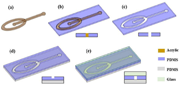
Figure 1. Fabrication scheme for PDMS microchannels, (a) acrylic template, (b) PDMS is casted on the acrylic template (c) PDMS is peeled from the acrylic template, (d) PDMS is bonded with another PDMS substrate (e) the chip is sealed by bonding the other side with glass.
Download figure:
Standard image High-resolution imageThe shape and features of microchannels are created using a Plexiglas® microstructure, obtained by cutting a Plexiglas® sheet, as the mold; the microchannel depth is varied by varying the thickness of the Plexiglas® sheet. Cutting is driven by the computer in accordance with the relevant AutoCAD design. The laser beam is scanned across a Plexiglas® sheet of the desired thickness; the scan path of the laser depends on the AutoCAD design. The speed, power and frequency of the laser beam are 25 mm s−1, 75 W, 500 DPI, respectively. The resulting Plexiglas® microstructure is fixed with double-side tape on the bottom of a petri dish. The silicone elastomer and curing agent, in the ratio of 10:1 weight, are mixed and kept in a vacuum chamber to remove the air bubbles. The degassed PDMS is poured into the petri dish in a controlled manner so that Plexiglas® microstructure just submerges. Afterwards a glass slide is placed on top of the Plexiglas® microstructure to prevent the spread of PDMS on top of the Plexiglas® microstructure as well as to level the surface; PDMS is then cured in an oven at 80 °C for about 2 h. After solidification, the cured PDMS is carefully peeled off from the petri dish and cut to allow access to the assembly. The patterned PDMS piece is permanently bonded to a PDMS substrate by plasma-bonding process for 2 min in the O2 plasma chamber, and punched to create the fluidic inlets and outlet. Finally, the chip is sealed with a glass slide or another PDMS layer via plasma bonding. The channel depth is controlled by tuning the thickness of the Plexiglas® sheet and this enables creation of microchannels with depth ranging from several micrometers to millimeters.
2.3. Experimental setup
The particle suspension is prepared as follows: 20 µl of magnetic particles with 4.3 µm diameter are dispersed in 10 ml deionized water by sonication for 5 min. The microparticle solution is contained in a 1 ml syringe and mounted on a syringe pump. Experiments are conducted by flowing magnetic particles through the microfluidic device and observing their trajectory in the microchannel, where a magnetic field is applied using an external magnet. Microparticles' trajectory is observed using the optical microscope, which is connected to a camera, under high magnification. The images and movies are processed with cellSens™ Microscope Imaging Software. The experimental setup of the microfluidic system is shown in figure 2.
The wire is positioned perpendicular to the flow direction with its long axis crossing the entire depth of the microchannel and embedded invasively at the center of the main microchannel. The wire is integrated into the microchannel manually after sealing of the chip; at the last stage of fabrication. The wire position can be controlled accurately by using a thin tipped-tweezer to implement the wire under the magnification of an inverted microscope, where a grid with microscale is positioned beneath the chip. DI-water is pumped from one inlet and it branches into two streams before entering the main microchannel from two opposing sides. The sample, carrying the magnetic microparticles, is pumped from another inlet and, once it enters the main microchannel, it is subjected to hydrodynamic focusing by which it is squeezed into a thin sheet to specifically approach the wire from its magnetically repulsive side. Since two magnets were kept at the two sides of the main channel with 4 mm distance from the wire for each. The wire is parallel and in the center of the two magnets, the north-pole facing the south-pole (12 mm side), so the magnetic field is perpendicular to the wire.
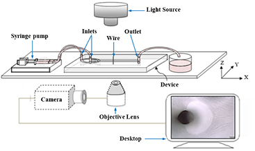
Figure 2. The experimental setup to investigate the microparticles separation on the stage of an inverted microscope, under flow conditions using the fabricated microfluidic device connected to a syringe pump.
Download figure:
Standard image High-resolution image3. Results and discussions
3.1. Device characterization
The microdevices presented in this work have two important features distinguishing it from existing microdevices. Namely, the use of a permalloy wire oriented vertically along the depth of the microchannel, and the utilization of a deep microchannel to realize high throughput. These features have been shown to be effective in separating magnetic microparticles. Several microdevices have been prepared, with precisely controllable dimensions, and tested using magnetic microparticles suspended in DI-water.
Each microdevice has two inlets and one outlet circular manifolds; each of 1.5 mm diameter. The overall length of the microchannel is 20 mm. The microchannel width is varied between 0.2 mm and 1 mm and the microchannel height is varied between 0.5 mm and 2 mm. Figure 3(a) shows an optical top view image of Plexiglas® microstructure. Figure 3(b) shows a side view of the microchannel, where the wire is inserted perpendicular through the whole depth (2 mm) of the microchannel. For the microdevice shown in figure 3(b), the microchannel width and height are 1 mm and 2 mm, respectively; the diameter of the permalloy wire is 254 µm. Besides showing the topography and shape of the microchannel which are obtained with optimized conditions (i.e. speed, power, and frequency of the laser beam). It is also evident from the figure that a small fraction of the material accumulates at the top edge of the channel wall. This behavior has been attributed to the softening of polymer density caused by the laser irradiation, resulting in increases in volume and rise of the material [36, 37]. Figure 3(c) shows a photograph of the microdevice with permanent magnets. Herein, the microchannel is filled with blue ink for purposes of visualization of the microchannel. The permanent magnets have a diameter of 12 mm and a thickness of 3 mm. Each external magnet is kept on either sides of the main microchannel with 4 mm distance between each of the magnets and the wire. The magnets are oriented such that the north pole of one magnet faces the south pole of the other; with this arrangement, the external magnetic field is perpendicular to both the wire's axial length and to the direction of flow of the magnetic microparticles. The wire produces two regions of high and low gradient magnetic fields, throughout the entire depth of the microchannel. That is used for the purpose of capturing and immobilizing the magnetic microparticles at the attractive sides of the wire.

Figure 3. (a) Optical microscope top view image of the microfluidic channel. (b) Side-section of the device, the effective depth of the channel is 2 mm, the wire is inserted along the whole depth, blue arrow indicates direction of the fluid flow. (c) Actual size photograph of the magneto-microfluidic setup showing the separation device and the holder with the external magnets.
Download figure:
Standard image High-resolution image3.2. Separation of magnetic particles in focused continuous flow
Initial experiments are conducted by injecting magnetic microparticles through the fabricated microfluidic device and observing their trajectories. The sample enters the microdevice through the central inlet manifolds and is subsequently focused by two side buffer streams (called 'sheath' flows) introduced through the other inlet manifold. The final focused width of the sample stream is a function of the flow-rates of central and sheath flows [38–40]. Hydrodynamic flow focusing is an important requirement of microfluidic particle separation devices, as it allows the microparticles to arrive sequentially to the separation region making detection easier. Figure 4 shows bright field microscope superimposed images of the magnetic particles in the microchannel at 10×magnification. DI-water is pumped from one inlet at 4 µl s−1 and branched into two streams before entering the main microchannel from two opposing sides. The sample carrying suspended magnetic particles' with size of 4.3 µm is pumped from another inlet at 1 µl s−1, and once it enters the main channel, it becomes subject to hydrodynamic focusing due to which it is squeezed into a thin layer. Figures 4(a) and (b) represents the laminar flow, in the absence of magnetic field, at the beginning and the middle of the main channel, respectively; from figure 4 it can be noticed that the presence of sheath flow focuses the suspension of magnetic microparticles.

Figure 4. Bright field microscopic superimposed images of the focused flow pattern of magnetic particles with size of 4.3 µm in the microfluidic channel in the absence of magnetic field. The images are constructed by overlaying sequential frames (15 frames s−1) of the corresponding time-lapse movies recorded at (a) the beginning of the main channel, (b) the middle of the main channel. The red and blue arrows indicate the direction of particles suspension flow and the sheath flow, respectively.
Download figure:
Standard image High-resolution imageFigure 5 shows bright field microscopic superimposed images of the focused flow pattern of magnetic particles in the microchannel. DI-water is pumped through an inlet manifold, which then branches into two streams before entering the main microchannel from two opposing sides, and the microparticle suspension is pumped in another inlet. The suspension of microparticles is subjected to hydrodynamic focusing in the main microchannel and the focused stream of microparticles specifically approaches the permalloy wire along its magnetically repulsive side. A uniform external magnetic field is applied perpendicular to the flow (x-direction) and the long axis of the wire (z-axis). This arrangement leads to a strong magnetic gradient, and attractive force symmetric with respect to the channel center axis on the two sides of the wire. In this way, the microparticles are attracted to the surface of the same (i.e. attractive sides) to form two dense plugs. Subsequent demagnetization of the wire releases the plugs to the stream which carries the microparticles to the outlet manifold. With the proposed method, increasing the depth of the microchannel does not affect the separation efficiency as there is no decay of the magnetic force along the depth.

Figure 5. Optical microscope superimposed images of the 4.3 µm magnetic particles in the microfluidic channel (a) in the absence of magnetic field, (b) and (c) in the presence of magnetic field. The flow rate for the sheath flow and particles suspension as (a) 4 µl s−1 and 1 µl s−1. (b) 4 µl s−1 and 1 µl s−1. (c) 3 µl s−1 and 1 µl s−1, respectively. The positive sign indicates the high magnetic field gradient side and the negative sign indicates the low magnetic field gradient side.
Download figure:
Standard image High-resolution imageFigure 5(a) shows the focused flow of the magnetic microparticles in the absence of magnetic field. The particles' suspension flow rate is 1 µl s−1 and the total sheath flow rate is 4 µl s−1. Figure 5(b) shows that the magnetic microparticles deflect when approaching the wire, i.e. the magnetic microparticles are repelled from the low magnetic field region towards the high field region. The particles' suspension flow rate is 1 µl s−1 and the total sheath flow rate is 4 µl s−1. Herein, the positive sign indicates the high magnetic field gradient side (i.e. attractive side of the wire) while the negative sign indicates the low magnetic field gradient side (i.e. repulsive side of the wire). Figure 5(c) shows the case where the flow rate of the suspension of magnetic microparticles is 1µl s−1 and that of the sheath flow is 3 µl s−1. It is observed that for this flow conditions, the width of the focused flow increased and the depletion area in the separation zone of the microchannel increased. This behavior is expected as reduction in sheath flow reduces the overall flow rate which in turn reduces the drag force acting on the microparticles. The reduction in drag allows for increase in the depletion area.
Separation of magnetic particles in focused continuous flow is investigated with a variety of flow rates. Where, the flow rate ratios of the sheath flow to particles' suspension are 2:1, 3:1, 4:1 and 5:1. The focusing effect will be observed only when the ratio of sheath flow to particles' suspension flow rate is maintained above its threshold. Increasing the ratio above this threshold will simply lead to decrease in the thickness of the focused flow with no appreciable changes to the separation process. Reduction in ratio below the threshold will not achieve focusing; nevertheless, separation will take place in the manner similar to that under unfocused conditions. Full capture of the magnetic particles is achieved for the all flow rates investigated. Experiment results demonstrate the capability of the device to separate magnetic microparticles from a suspension with high purity and high throughput. It is observed that changing the flow rate did not affect the separation efficiency in focused continuous flow experiments. The experimental observation is similar to the simulation results by authors in [6, 22], where a computational fluid dynamic (CFD) is used, the proposed model demonstrated that flow-invasive magnetic elements provide substantial performance advantages, and enhanced separation efficiency over conventional bioseparation systems, where multiple stair-step elements were used to provide efficient capture throughout the entire flow channel.
Figure 5(a) shows the particles' path in the absence of magnetic field. When subjected to magnetic field the particles will be drawn towards the magnetic element as shown in figure 5(b). Thus, if this device is used for separating magnetic and non-magnetic microparticles then the magnetic particles will be drawn to the magnetic element while the non-magnetic particles will continue to the outlet of the microfluidic device thereby achieving separation. Since the non-magnetic particles have no net magnetic moment, so they exhibit no collective interaction with the magnetic field. The particle–particle interaction can be neglected because the sample is dilute. This approach is schematically represented in figure 6.

Figure 6. Schematic diagram showing top-view of a microchannel with focused flow, and the wire embedded in the center of the microchannel, demonstrates the separation of magnetic and non-magnetic particles in the presence of magnetic field.
Download figure:
Standard image High-resolution image3.3. Separation of magnetic particles in unfocused continuous flow
Figure 7 shows bright field microscope superimposed images of the magnetic microparticles in the microchannel at 10×magnification. For this case, there is no sheath flow. Figure 7(a) shows laminar flow for the magnetic microparticles' suspension, movement of microparticles are observed in the absence of sheath flow and magnetic field at flow rate of 1 µl s−1. Figure 7(b) demonstrates the separation of microparticles in the presence of magnetic field at a flow rate of 4 µl s−1. For this flow rate, not all microparticles are captured by the wire as the acting hydrodynamic drag force is greater than the attractive magnetic force. Figure 7(c) demonstrates the separation of particles in the presence of magnetic field for a flow rate of 1 µl s−1; for this case, none of the particles is escaping through the channel outlet. However, the capture efficiency due to the wire itself is not equal to 100%. At such relatively slow velocity, more particles will be repelled from the wire to eventually hit, and therefore dissipate most of their momentum to, the wall of the channels. After hitting the wall, particles will have little momentum to bounce back into the channel and therefore will be trapped therein. Very small portion of the particles hitting the wall can be siphoned into the attractive region of the wire. With that, the reduction in the flow rate of the unfocused sample carrying the particles has the effect of increasing the portion of particles that stick to and agglomerate on the wall and therefore preventing them from escaping the channel outlet. The observed particles trajectories with respect to the invasive embedded magnetic elements (i.e. the wire) are in close agreement with the simulations [6, 22]. Figure 7(d) shows a plug formation on the attractive region of the wire. With the continuous flow of the microparticles suspension, under the effect of the applied external magnetic field, magnetic microparticles are separated from the fluid and either attracted towards the attractive side of the wire or repelled toward the walls. The microparticles trapped on the wire can be released back into the fluid by removing the external magnets, i.e. once the wire returns to its un-magnetized state. Thus, the force it produces for particles capture by the wire can be switched on and off by simply applying and removing a bias field, thereby enabling the separation of magnetic particles from a sample and its subsequent release in higher concentration on demand for further analysis.

Figure 7. Bright field microscopic superimposed images of magnetic particles with diameters of 4.3 µm in the microfluidic channel in the (a) absence of magnetic field. (b) and (c) presence of magnetic field, separation demonstrated here was performed without sheath flow and a particles' suspension flow rate of; (b) 4 µl s−1 (c) 1 µl s−1. (d) A zoomed-in image of the wire surface, agglomeration of particles towards the attractive side of the wire was observed.
Download figure:
Standard image High-resolution image3.4. Effect of flow rate on magnetic particle separation
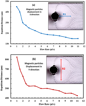
An experimental investigation of the displacements of the magnetic microparticles with respect to flow rate is introduced here. Experiments are carried out using magnetic microparticles, with diameter of 4.3 µm, for magnetic microparticles' suspension flow rates ranging from 1 µl s−1 to 11 µl s−1. The same set up and parameters were used as in the previous section. Under different flow rates, the recorded images, shown in figure 8, clearly marks the microparticles depletion zone which is characterized by displacements R1 and R2. R1 is the maximum depletion distance in x-direction and R2 is the maximum depletion distance in y-direction as depicted in figure 8. The displacement R1 decreases from 500 µm to 200 µm as the flow rates increase from 1 µl s−1 to 11 µl s−1 as shown in figure 8(a). The displacements R2 decrease from 825 µm to 425 µm as the flow rates increase from 1 µl s−1 to 11 µl s−1 as shown in figure 8(b). The increase of R1 and R2 with decreasing the flow rate is attributed to the decrease of the hydrodynamic drag force of the particles relative to the opposing repulsive force, so magnetic microparticles are drawn to the attractive side of the wire from a longer distance, and are repelled from the repulsive side of the wire from a longer upstream distance. A smaller effect (i.e. the particles depletion area is becoming smaller) is obtained with reduced sample flow rate.
Figure 8. The graphs of magnetic particles repulsion distances in the separation zone of the microchannel, at the wire position under varies flow rates in (a) X direction (R1), (b) Y direction (R2).
Download figure:
Standard image High-resolution image
The disadvantage of increasing the flow rate above 2 µl s−1 is the increase in the number of particles escaping through the channel outlet, i.e. particles neither get attracted by the wire nor trapped at the channel wall (figure 6(b)). In that sense, one can say that the 'filtration' efficiency (i.e. particles being prevented from escaping the channel, either due to their direct attraction toward the wire itself or due to their retention on the wall by the induced repulsion), increases by decreasing the sample flow rate. In this case study, when focusing is not employed, the flow rate should be less than 2 µl s−1 to obtain a 100% filtration efficiency,. However, it should be clearly noted that the complete filtration does not necessarily mean that the capture efficiency at the wire itself is 100%. Thus, there exists a threshold flow rate above which a magnetophoresis based microdevice will not yield 100% filtration efficiency. As a comparison, figure 7(c) shows a complete filtration (separation) at the sample flow rate of 1 µl s−1 without sheath flow focusing. On the other hand, figure 5(b) shows that for the same sample flow, but with being hydrodynamically focused using a 4 µl s−1 sheath flow, a complete filtration is achieved as well. However, with focusing the complete capture is exclusively attributed to the attraction to the wire itself and none due particles retention on the channel wall. With that, focusing becomes advantageous when the separation/capture is targeted at a confined region. Unlike the case with unfocused sample flow, focusing ensure capture to be confined on the wire and therefore facilitates for more applications especially those involving simple collection of the captured entities or their surface modifications.
4. Conclusion
A microfluidic device for separation of magnetic microparticles under continuous flow is developed and tested. The novel feature of the microdevice is the utilization of a vertically oriented permalloy wire that spans through the entire depth of the microchannel to cope with the short-ranged magnetic force induced by the permalloy wire. In addition, the microdevice is fabricated via a simple process where the effective height of the device can be increased up to thousands of micrometers, thus increasing the throughput of the particles by simply increasing the microchannel depth. The microdevice performance is investigated under hydrodynamically focused continuous flow that verified the capability of the microdevice to separate magnetic microparticles from a suspension with 100% capture purity and at high throughputs, where changing the flow rate does not affect the separation efficiency. While in unfocused continuous flow, the capture efficiency decreased as the flow rate increase; it showed perfect filtration/separation efficiency with the optimized flow rates but not necessarily perfect capture at the wire itself. Experimental results revealed a significant improvement in throughput and scalability when using flow-invasive soft magnetic elements as compared to the conventional systems that use elements exterior to the flow. Thus, the demonstrated microdevice can potentially be useful for separation, detection, and purification of microparticles as well as biological entities (biomolecules and biological cells) in lab-on-a-chip devices.
Acknowledgment
The Authors acknowledge financial support received from the UAEU Start-up research fund, project no. 31N158, UAE.