

Abstract
In this study, bridge-type micro-hotplates (MHP) with an SU-8 supporting layer were proposed for smart gas sensor applications. The proposed MHP consisted of a heating membrane with an area of 140 µm × 140 µm, and a 33 µm-thick SU-8 layer deposited on its bridges. Finite element method based simulation confirmed that the proposed MHP displayed good thermal isolation properties. The proposed MHP was successfully fabricated, and the properties of the MHP were characterized. Current–voltage characteristics revealed that the MHP temperature can reach 550 °C at 5 V. The temperature of the MHP was calculated from changes in the resistance of the heater. Power consumption of the MHP approximately corresponded to 13.9 mW for heating to 300 °C. This was comparable to the power consumption reported in the previous studies. Furthermore, a stable operation under a constant voltage was observed for 100 min. The properties of the MHP indicated that it could potentially be utilized for applications related to integrated gas sensors.
Export citation and abstract BibTeX RIS
1. Introduction
Semiconductor gas sensors are one of the most widely used gas sensors. They are used for a variety of applications in our daily lives such as providing an alert related to the leakage of combustible gases and monitoring air quality in rooms and motor vehicles [1]. Tin oxide (SnO2) is among the most frequently used materials for semiconductor gas sensors [2]. Several other metal oxides, such as and zinc oxide (ZnO) and tungsten oxide (WO3) are also used in gas sensors [3, 4]. These metal oxides are used to detect a wide range of gases including carbon monoxide (CO), hydrogen (H2), nitrogen oxides (NOx), and carbon dioxide (CO2) as reported in a number of previous studies [3–8].
Recently, advances in semiconductor technology have led to the development of sensor chips integrated with gas sensors and driving circuits that are termed as smart gas sensors [9, 10]. Furthermore, sensor chips integrated with multiple sensors were also developed. Hagleitner et al reported a sensor chip in which several types of gas sensors including mass-sensitive, calorimetric, and capacitive gas sensors are integrated with driving circuits [11]. Futagawa et al proposed a multimodal sensor that is an integrated sensor that includes sensors to measure electrical conductivity, pH, and temperature to realize multiple functions [12]. To-date, extant research has not demonstrated multimodal sensors including gas sensors. However, these sensors have the potential to bring tremendous innovations in the field of gas sensors. In order to miniaturize the size of the sensor chips, the dense integration of these sensors is necessary. This in turn may lead to the ease of installation of these chips in various situations.
The operation of semiconductor gas sensors requires sensing materials in the sensors to be heated at temperatures in the range of 300 °C–450 °C [2, 13]. Hence, micro-hotplates (MHP), which include a heating structure that consists of a suspended dielectric membrane and a heater resistor, are required to avoid an increase in the substrate temperature and to thereby thermally isolate semiconductor gas sensors integrated with electronic circuits [14]. There are three types of MHP structures, namely, membrane-type [15–17], bridge-type [18–21], and silicon-on-insulator (SOI) based structures [22, 23]. Bridge-type MHP possess the most superior thermal isolation properties that are beneficial for low-power operation and high-density integration. Hence, a bridge-type MHP is desirable for smart gas sensors and multimodal sensors. However, it is necessary to carefully consider the residual stress in the membrane, which consists of the heating area and the bridges, due to its structural fragility. In order to reduce the residual stress in MHP, low-stress silicon nitride (SiN) and multilayer structures are generally used to fabricate the membrane of a MHP [15, 17, 18, 21]. However, the residual stress of the SiN can be altered via thermal treatments [15, 24]. Hence, it may be difficult to control the residual stress in SiN since the fabrication of a MHP integrated with driving circuits involves various thermal processes. Conversely, in a multilayer structure, the residual stress is relieved because the stress on each layer is distributed across the layers. Additionally, an increase in the thickness of the membrane improved robustness against external forces. Therefore, a multi-layered thick membrane (in the order of 10 µm) is a solution for a stress-tolerant MHP. However, thermal conduction to the substrate increases as the membrane becomes thicker, and this results in an increase in the power consumption and an increase in the substrate temperature. In the present study, a structure with the bridges supported by a thick film with low thermal conductivity, was proposed. In proposed structure, SU-8 was employed as the support material. SU-8 is an epoxy-based permanent resist [25], and it is easy to deposit an SU-8 film with a thickness of tens of micrometers via spin-coating. This is approximately 10 times thicker than the typical thickness of the membrane layer. Additionally, SU-8 displays good mechanical stability and was used as a structural material for microfluidic channels [26, 27] and actuators [28]. With respect to the thermal properties, SU-8 exhibits a smaller thermal conductivity by approximately an order of magnitude when compared with silicon dioxide (SiO2), which is typically used for the membrane. Therefore, it is expected that the MHP will display good thermal isolation properties even when an SU-8 film with a thickness of tens of micrometers is deposited to ensure sufficient mechanical strength. Thus, this study also involves investigating properties including the thermal isolation property, operation temperature, and power consumption.
2. Design and electro-thermal simulation of the MHP
2.1. Design of the MHP
Figure 1 shows the schematic illustration of (a) the top view and (b) cross section of the proposed MHP. The heating membrane consisted of a stack of SiN and SiO2. The SiN/SiO2 stack layer was formed on a silicon (Si) substrate. A meander shaped polycrystalline Si (poly-Si) with a width of 20 µm was formed on the dielectric layer as a heater material. Interdigitated sensing electrodes of platinum (Pt)/titanium (Ti) stack were patterned with an insulating layer of SiN on the heater. An additional SiO2 layer was formed on the bridges and a part of the membrane protected the wiring of the heater and electrode. Finally, an SU-8 layer was formed to support the bridges. Additionally, a Si layer (Si island) was formed under the membrane to improve the temperature uniformity of the membrane as shown in figure 1(b). The area of the membrane corresponded to 140 µm × 140 µm.
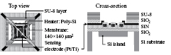
Figure 1. Schematic illustrations of top view (left) and cross section (right) of the proposed MHP. The upper SiO2 layer is not shown in the left figure. The location of the cross section is indicated as a white dashed line in the left figure.
Download figure:
Standard image High-resolution image2.2. Electro-thermal simulation of the MHP
2.2.1. Condition for the simulation.
Electro-thermal simulation was performed by a finite element method using ANSYS®. Figure 2 shows the structure for the simulation. A major difference in the structure between figures 1 and 2 is that the sensing electrodes were omitted in the simulated structure, and additionally, the length of the wiring was also slightly different. Bias voltages were applied between the Pt wire that was connected to the poly-Si heater, and the temperature distribution was calculated. Calculations were also performed for the structure without the SU-8 layer to investigate the thermal insulation property of the SU-8 supported MHP by comparing these two structures. The area of the Si substrate corresponded to 1 mm2. The environmental temperature was set as 22 °C. Other parameters were determined according to those in previous studies [23, 29]. Table 1 shows the parameters used in the calculation [23, 25, 30, 31]. Thermal conductivity and specific heat generally change with temperature, and thus, their temperature dependence should be taken into account for accurate treatments. However, the data related to temperature dependent thermal conductivity and specific heat of membrane materials including SiO2 and SiN were insufficient, and they change even with the deposition condition of membrane materials. Thus, it was difficult to perform this type of treatment. Conversely, the objective of the simulation involved examining the thermal isolation property of the proposed MHP. This was confirmed by comparing the proposed MHP to the structure without the SU-8 layer. Even for the comparison, the temperature dependence of thermal conductivity and specific heat of the SU-8 can cause errors. Nevertheless, in polymer materials, there is only a slight temperature change in the thermal conductivity, while the temperature change in the specific heat is mostly less than twice above room temperature [32]. Therefore, the conclusion of the simulation may hold even if the thermal conductivity and specific heat of the SU-8 were set as constant. Hence, constant values was employed for these parameters. Heat transfer coefficient corresponded to the empirical parameter describing the heat transfer to air including the effect of convection. It is difficult to determine the coefficient. Thus, in this study, according to previous studies [23, 29], heat transfer coefficients were set as 125 Wm−2 K−1 for the surface and side wall of the chip and 60 Wm−2 K−1 for the back side of the membrane. Conversely, the bottom surface of the Si substrate was in contact with a package in an actual situation acting as an optimal good heat sink. Therefore, given the assumption of a smooth heat transfer, the heat transfer coefficient of the bottom surface of the Si substrate was set as 1000 Wm−1 K−1. The maximum temperature range obtained in the simulation was at most 300 °C, and the effects of the radiation were probably insignificant in the temperature range [29]. Thus, radiation was not considered in the simulation.
Table 1. Parameters used for simulation.
| Material | Thermal conductivity (Wm−1 K−1) | Specific heat (J kg−1 K−1) | Density (kg m−3) | Thickness |
|---|---|---|---|---|
| Si |
156 | 713 | 2329 | 525 µm (substrate) |
| 50 µm (island) | ||||
| SiO2 |
1.4 | 1000 | 2270 | 620 nm (lower) |
| 500 nm (upper) | ||||
| SiN | 19 |
750 |
3100 |
200 nm |
| Poly-Si |
28 | 750 | 2330 | 300 nm |
| Pt |
72 | 133 | 21 450 | 300 nm |
| SU-8 |
0.2 | 1500 | 1190 | 35 µm |

Figure 2. Structure used for the simulation. The sensing electrodes and the wirings are excluded in the structure. The location of the cross section is indicated by a white dashed line in the left figure.
Download figure:
Standard image High-resolution image2.2.2. Simulation results.
Figure 3 shows the temperature distributions of the MHP (a) without and (b) with the SU-8 layer. An applied voltage was set such that the temperature near the center of membrane was 300 °C, which corresponded to a typical operating temperature of semiconductor gas sensors. In figure 3(a), the temperature in the peripheral region of the membrane maintained near the room temperature (RT) (approximately 26 °C) without the SU-8 layer, while the temperature was approximately 28 °C in the structure with the SU-8 layer as shown in figure 3(b). Although the substrate temperature slightly increased due to the increase in the heat flux because of the SU-8 layer, the difference between the two cases (with and without SU-8 layer) was a maximum of 2 °C, indicating that the MHP had a sufficient thermal isolation property even with a 35 µm-thick SU-8 layer on the bridges.
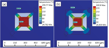
Figure 3. Calculated temperature distribution of the MHP (a) without the SU-8 and (b) with SU-8 layer.
Download figure:
Standard image High-resolution image3. Fabrication of MHP
The MHP was fabricated on a p-type (1 0 0) Si wafer. Figure 4 shows a schematic representation of the MHP fabrication process. First, SiO2 with a thickness of approximately 620 nm was thermally grown. A 100 nm-thick SiN was then deposited by low-pressure chemical vapor deposition (LPCVD) to form the base layer of the membrane (figure 4(b)). Poly-Si with a thickness of approximately 330 nm was deposited on the SiN/SiO2 layer by LPCVD followed by phosphorus doping. The doping was performed by thermal diffusion using phosphorus oxychloride (POCl3) gas at 1050 °C. The sheet resistance (Rsh) of the doped poly-Si was approximately 17 Ω sq−1, which corresponded to the resistivity of 5.6 × 10⁻⁴ Ω cm. Poly-Si was then patterned by reactive ion etching (RIE) to form the heater resistor. Following this, 100 nm-thick SiN was deposited as an insulation layer followed by opening the contact hole for the heater (figure 4(c)). A Pt/Ti layer was then deposited by sputtering and patterned by a lift-off process. The Pt/Ti layer acted as a sensing electrode and wiring of the heater. As a protective layer of the wiring, an SiO2 layer with a thickness of approximately 500 nm was deposited by plasma-enhanced CVD (PECVD) (figure 4(d)). A 500 nm-thick SiO2 (PECVD) was also deposited on the back surface of the wafer. It should be noted that the layers described above except for the Pt/Ti were also deposited on the back side. Particularly, a 500 nm-thick PECVD SiO2 and 620 nm-thick thermal oxide formed on the backside effectively acted as the etching mask for deep RIE (DRIE) [33]. These layers under the membrane were etched to pattern the mask for the DRIE (figure 4(e)). Following this, an SU-8 layer was deposited to support the bridges (figure 4(f)). The obtained thickness of the SU-8 layer was approximately 33 µm. After the photoresist (PR) patterning as the mask for the Si island formation (figure 4(g)), bulk Si was etched by DRIE to release the membrane and bridges (figure 4(h)). The PR with the area of 130 × 130 µm2 was patterned inside the membrane. Although the PR functioned as an etching mask at the beginning of the DRIE, the resist mask was etched away prior to the completion of the bridge release. Thus, after the resist was removed, Si etching under the membrane region progressed. When DRIE was finished, the mask layer on the back side was etched to the thermal oxide layer. Additionally, xenon difluoride (XeF2) gas was used to remove the Si remnants under the bridges. As a result, an approximately 50 µm-thick Si island remained under the membrane when the bridge release was completed. It should be noted that the thickness of the Si island can be accurately controlled by using the SiO2 mask under the membrane with an appropriate thickness by considering the etching rate of SiO2 and Si.

Figure 4. Schematic of the MHP fabrication process.
Download figure:
Standard image High-resolution imageThe optical microscopy images of the fabricated MHP are shown in figure 5. The central membrane is suspended by the four bridges, and the white solid squares indicate the edges of the SU-8 layer. The heating area corresponds to the inside of the inner square on which the heater and the sensing electrodes are formed. It was confirmed that the MHP was successfully fabricated without significant cracks and damages.

Figure 5. Optical microscopy image of the fabricated MHP. The membrane is suspended by the four bridges. The edges of the SU-8 layer are indicated by the white solid squares. The heating area corresponds to the inside of the SU-8 edge (the inside of the inner square). Significant damages and cracks were not observed.
Download figure:
Standard image High-resolution image4. Electrical characterization
4.1. Electrical properties of the heater
The temperature dependence of the heater resistance was measured to investigate the electrical properties of the heater. The measurements were performed on the samples prior to releasing the membrane during the heating with a hotplate under vacuum. Figure 6(a) represents the temperature dependence of I–V characteristics of a poly-Si heater for the temperature range of 25 °C–440°C. The slope of the characteristics decreased due to the increase in the resistance as the temperature increased. Figure 6(b) shows the resistance of the heater plotted relative to the temperature. Resistance value at a bias voltage of 50 mV was employed to avoid the self-heating effect to the maximum possible extent, although almost linear I–V characteristics were obtained in the voltage range of 0–2 V. The resistance was approximately 414 Ω at 25 °C and increased with temperature to reach 637 Ω at 440 °C. Here, according to a previous study [34], the result was fitted by a second-order polynomial as follows:

where R(T) denotes heater resistance at temperature T, and a0, a1, a2 denote the fitting parameters. The fitting result is shown as a dashed curve in figure 6(b) in which a0, a1, and a2 corresponded to 414.1 Ω, 0.1404 Ω °C−1, and 7.794 × 10⁻⁴ Ω °C−2, respectively. The temperature dependence of the resistance of the poly-Si is discussed in this section. The resistivity of the poly-Si in this study was approximately 5.6 × 10⁻⁴ Ω cm. Although it was difficult to obtain the dopant concentration from the resistivity of the poly-Si, the resistivity of 5.6 × 10⁻⁴ Ω cm in single crystalline silicon corresponds to the phosphorus concentration beyond 1020 cm−3 [30]. With respect to this level of a concentration, Si is almost degenerated, and thus, poly-Si was also degenerated because the resistivity of poly-Si is generally larger than that of single crystalline silicon. Given the increase in the resistivity with temperature, the temperature dependence of the resistivity may be dominated by the mobility change. At temperatures exceeding 200 K, the mobility of heavily-doped poly-Si is dominated by phonon scattering [35]. The mobility due to phonon scattering linearly decreases with temperature in a metal [36], while it changes by T−2.4 in low-doped Si [30]. Because the resistivity is inversely proportional to the mobility, the temperature dependence of the resistivity could lie between T and T2.4 for the degenerated poly-Si as shown in this study. Consequently, it was reasonable to use a second-order polynomial for the fitting.

Figure 6. (a) Temperature dependence of current–voltage characteristics of poly-Si heater prior to releasing the membrane. (b) Resistance plotted with respect to temperature in which the resistance values at 50 mV were employed. The resistance increased with temperature. The dashed curve in (b) represents the result of fitting by a second-order polynomial.
Download figure:
Standard image High-resolution image4.2. Heating characteristics of the MHP
In this section, the temperature at which the MHP was reached was estimated from the resistance change in the heater. The power consumption of the heater was then evaluated. The operation of the MHP under a constant voltage was also described. Finally, the operable temperature of the MHP was discussed.
4.2.1. Estimate of the MHP temperature.
Figure 7(a) shows the I–V characteristics of the heater in the MHP with the SU-8 layer after the membrane release. The corresponding resistances were simultaneously plotted. It should be noted that the measurements were performed in a different element from that mentioned in section 4.1. In contrast to figure 6(a), nonlinear I–V characteristics were obtained wherein the resistance increased from 367 Ω at 50 mV to 637 Ω at 5 V. These results indicated the increase in the temperature of the heater, and thus the increase in the MHP temperature, with increases in the bias voltage. Assuming that the temperature of the MHP was almost identical to that of the heater [18], then the temperature of the MHP was calculated in the following procedure. Although the fitting result described in section 4.1 includes geometric factor (length and width, etc), its normalized value with R(T0): R(T)/R(T0) is independent of the shape of the resistor, in which T0 is an arbitrary temperature. Thus, the following relationship between two different resistors (R1, R2) holds:

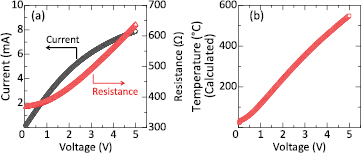
Figure 7. (a) Current–voltage and resistance–voltage characteristics of the heater after releasing the membrane. The resistance of the heater increased with voltage, and this indicated the increase in the temperature of the heater. (b) MHP temperature calculated from the resistance of the heater. The figure shows that the temperature could reach 550 °C at 5 V.
Download figure:
Standard image High-resolution imageAssuming that R1(T) and R2(T) are resistances measured in section 4.1 and the resistance shown in figure 7(a), respectively, equation (2) can be rewritten as follows:

By solving equation (3) with regard to T under the condition of T > 0, the following is obtained:

where k is R2(T0)/R1(T0). Therefore, the temperature can be calculated from the measured resistance (R2(T)) by equation (4). The temperature of the heater was then calculated for T0 of 22 °C (room temperature during the measurements) wherein the resistance at a bias voltage of 50 mV was employed for R2(T0), and R1(T0) was obtained from the fitting result. The calculation results were plotted relative to the voltage in figure 7(b). As shown in the figure, the results indicated that the temperature could reach approximately 550 °C at 5 V. Poly-Si can recrystallize at such a temperature. However, in this study, it was annealed at 1050 °C during the doping as described in section 3, leading to the crystallization. Thus the effect of recrystallization during I-V measurements may be negligible. Additionally, based on the discussion in section 4.1, it is likely that phonon scattering still dominated even at 550 °C, while the influence of carrier concentration change could be small with respect to a degenerated Si. Hence, calculating temperature by extrapolating the fitting result even at 550 °C may be valid, although there are still a few errors to some extent.
4.2.2. Power consumption.
The relationship between temperature and voltage was obtained in section 4.2.1. Then, as shown in figure 8, the temperature was replotted against the corresponding power consumption. The power consumption for heating the MHP to 300 °C was approximately 13.9 mW. Table 2 compares the power consumption of the MHP with that of previous studies, in which the reports on the MHP with dimensions similar to the device in the present study were employed. The obtained power consumption in this study was comparable to that in previous studies except for a particular extant study [21]. The addition of the SU-8 layer was likely to cause the increase in the power consumption. Nevertheless, it also changed with the other structural differences of the MHP including the dielectric layer consisting of the membrane, the ratio of the membrane area to the active heating area, and the existence of the Si island. Specifically, it was pointed out that power consumption decreases as the ratio of the membrane area to the heating area increases [14]. Given these structural influences, the results indicated the superior performance with respect to the power consumption of the MHP with the SU-8 layer. Additionally, the MHP layout in this study was not optimized for low power operation because the device in this study is designed to investigate the fundamental properties of the MHP with SU-8 support. As discussed later, it may be possible to further reduce the power consumption by optimizing the MHP design. Consequently, the results suggested the potential for a low power operation of the bridge-type MHP even with a 33 µm-thick SU-8.
Table 2. Comparison of the power consumption of the MHP obtained in the present study with those in previous studies.
| [20] | [22] | [21] | This work | |
|---|---|---|---|---|
| MHP structure | Bridge | SOI | Bridge | Bridge |
| Active area | Not available (120 × 120 µm2 from an SEM image) | 150 µm φ | 120 × 120 µm2 | 140 × 140 µm2 |
| Si island | − | − | − | + |
| Power for 300 °C | 12 mW | 17 mW | 55 mW | 13.9 mW |

Figure 8. Calculated MHP temperature plotted with respect to the power consumption of the heater.
Download figure:
Standard image High-resolution image4.2.3. Operation under a constant voltage.
The operation of MHP was also characterized under the application of a constant voltage for 100 min. Figure 9 shows the resistance–time (R–t) characteristics of the heater. The voltage was set as 3.03 V, which corresponded to the MHP temperature of approximately 356 °C. The resistance gradually increased during the measurements wherein the increase was 0.08% when compared with the initial value. Additionally, the results revealed that the voltage necessary to heat the MHP to 356 °C increased by only 0.01 V even after the measurements under a constant voltage. As a result, stable operation of the MHP was obtained at 356 °C for 100 min. Figure 10 shows the microscopy images of the MHP after the measurements. The SU-8 layer near the edges of the membrane appeared to be black when compared with the color prior to the measurements. It was reported that the weight loss of SU-8 could occur above about 277 °C [37], while the simulation result indicated that the temperature near the edges of the membrane could reach 240 °C (see figure 3). Given that the temperature of the onset of weight loss and glass transition of SU-8 depends on its deposition condition [25, 28], it was possible that such weight loss or degradation occurred during the measurements, and this may result in a change in the appearance after the measurements. Although the degradation of SU-8 was observed near the edges of the membrane, such degradation can be avoided by improving the design of the device as discussed in the next section. In contrast, no significant changes were observed in the SU-8 on the bridges.

Figure 9. Time-dependent resistance change under a constant bias voltage. The voltage was set such that the MHP temperature was 356 °C. Although the resistance gradually increased with time, the increase was only 0.08% with respect to the initial value.
Download figure:
Standard image High-resolution image
Figure 10. Optical microscopy image of the MHP after the measurements.
Download figure:
Standard image High-resolution image4.2.4. Discussion on the operation temperature and future outlook.
Finally, a limitation of the operation temperature and the prospects for improvements in the performance of the proposed MHP are discussed. Evidently, the thermal property of SU-8 limited the maximum operation temperature of the MHP. The glass transition temperature (Tg) of SU-8 is near 200 °C [25], above which SU-8 becomes rubbery, and thus its function as a mechanical support would be lost. Thus, it is necessary to avoid heating the SU-8 above Tg. Conversely, the temperature near the rims of the MHP was calculated as exceeding 200 °C when the temperature near the center of the membrane was approximately 300 °C in the simulation (figure 3). Additionally, the MHP temperature reached 550 °C during the I–V measurements. In these situations, the SU-8 temperature was expected to significantly exceed Tg, and excessively high temperatures could affect the reliability in terms of long-term stability of the SU-8. Specifically, the appearance of the SU-8 changed after the measurements as described in section 4.2.3. This disadvantage with respect to temperature can be improved by optimizing the MHP design while ensuring the mechanical robustness explained as follows. With respect to the robustness, the most vulnerable part of a bridge-type MHP involves its bridges. Therefore, supporting the bridges with SU-8 may be sufficient to improve its robustness. In this case, the SU-8 temperature near the bridges determines the maximum temperature. Conversely, the temperature rise near the bridges can be suppressed by enlarging the membrane area relative to the active heating area, because the temperature gradient occurs within the membrane due to its low thermal diffusivity. Figure 11 shows the simulation result in a structure similar to that in figure 3(b), except for the membrane area. The length of the membrane was enlarged to twice the original length while the heater area and the dimension of the Si island remained constant. The result clearly indicated that the temperature near the bridges decreased when compared with that in figure 3(b). Additionally, a larger membrane area is also beneficial in reducing the power consumption because heat flux decreases as the membrane enlarges, which was experimentally proved [29]. Thus, there should be a trade-off between the shrinkage of the membrane area and the maximum operation temperature as well as power consumption under a constant heating area. An exceedingly large membrane area compared with the heating area impairs the ability of the bridge-type MHP in high-density integration. However, a MHP that is denser than the present membrane-type MHP can be achieved by optimizing the ratio of the membrane area to the heating area adequately. Therefore, it may be stated that the MHP proposed in this study is promising for the application to smart gas sensors and multimodal sensors. Future studies will examine an improvement in the design of the MHP with SU-8 support from the fore-mentioned viewpoint.

Figure 11. Simulation result of the temperature distribution in the MHP involving SU-8 with an enlarged membrane.
Download figure:
Standard image High-resolution image
5. Conclusions
In this study, a bridge-type MHP with an SU-8 supporting layer was proposed for high density integration in smart gas sensors and multimodal sensors, and its properties were investigated. The MHP included a membrane with an area of 140 µm × 140 µm, which was suspended by four bridges, and a 33 µm-thick SU-8 layer was deposited on the bridges. FEM simulation confirmed that the MHP had a sufficient thermal isolation property. The MHP was successfully fabricated without significant damages. The MHP temperature was calculated from the changes in the resistance of the heater. The results indicated that the MHP temperature could reach 550 °C at a bias voltage of 5 V. Power consumption of the MHP at 300 °C was estimated as 13.9 mW, and this verified that the low power operation was comparable to that of other MHPs. The results also revealed that the MHP stably operated under a constant voltage at 356 °C for 100 min. In addition to the discussion on the improvements in the MHP design, these results indicated promising properties of the proposed MHP with respect to realizing high-density smart gas sensors and multimodal sensors.
Acknowledgments
This work is supported by JSPS KAKENHI Grant Number 15K18049.