
Abstract
The inverse scattering problem for inhomogeneous media is considered within the topology optimization framework. Varying the complex-valued refractive index we derive a zero-order necessary optimality condition in minimizing the L2 misfit cost functional of the far-field measurement. The topology asymptotic expansion of the optimality condition leads to an imaging operator, which is used to identify the center of the unknown inhomogeneity using few far-field measurements. Numerical tests show high precision and stability in the reconstruction using our optimality condition based imaging both in two and three dimensions.
1. Introduction
We consider the inverse scattering problem for the inhomogeneous media modeled by the Helmholtz equation in two and three dimensions. Such problems arise e.g. in non-destructive testing, medical imaging and many other areas of science and engineering. A popular class of methods for solving these problems, called qualitative methods, are able to quickly and accurately determine the shape and location of hidden objects and some information on the refractive index (at best), and require little a priori information about the objects. They are non-iterative in nature and do not require large scale wave simulations as oppose to iterative methods [15, 20, 26, 27, 35], however the latter recover everything (when possible) about the inhomogeneity. We refer the reader to [9–11, 30] for a comprehensive account on the linear sampling methods and factorization method for the inhomogeneous media. Many other non-iterative techniques are developed, including point source methods [39], enclosure method [24], MUSIC [4, 38], and one wave methods [25, 36, 40] (our references are not exclusive since the literature on these methods is quite large).
A different point of view that has also led to non-iterative type techniques for solving inverse problem stems from the shape optimization. Our study falls in this category. Identification of small inhomogeneities in the context of shape optimization is developed in [8, 18]. Based on topological derivatives [14, 17, 42], the optimization approach was adapted to inverse scattering problems in [2, 5, 6, 13, 19, 41] (see also references therein). The first-order topological derivative specified for small inhomogeneities with real-valued refractive index can be found in [1, 3], and the high-order topological expansions are derived in [7, 22, 31]. The asymptotic analysis in combination with perturbation theory is used in the framework of topological sensitivity for many inverse problems (see e.g [21, 28, 34, 37] and references therein).
More specifically, in this study we consider an inhomogeneity of the arbitrary shape described by a bounded region , d = 2, 3 centered at x0 and constant refractive index n. With respect to a parameter , this domain is rescaled to fit in a ball of radius ε centered at x0; this epsilon is referred to as the size of this scaled inhomogeneity. We setup the inverse problem as a minimization of the L2-least square misfit cost functional for a given measurement of the far-field pattern. The condition of feasible measurement expressed in a weak form (see (17)) provides us with the zero-order necessary optimality condition which is derivative-free. Then applying asymptotic arguments as the size to the optimality condition we derive an imaging function determined only by the incident field and far-field measurements. This enables us to accurately and stably reconstruct the center x0 of the inhomogeneity with the minimum number of measurements needed being equal to the dimension d = 2, 3. This work extends to the case of inhomogeneous media the method proposed in [32] where similar type of imaging function was introduced to identify the center of an impenetrable impedance obstacle from boundary measurements. Our result could be used in combination with other perturbation techniques to augment the recovered information about small inhomogeneity (e.g. known the center of the inhomogeneity we could use the formulas in [12] to recover the refractive index). Our zero-order optimality condition could possibly motivate the construction of other imaging functions that could work for broader class of inhomogeneous media. We present here a variety of numerical example showing the accuracy of our reconstruction method as well as indicating what could happen in cases when our theory does not apply, e.g. in the case of multiple inhomogeneities or inhomogeneities with absorption.


2. Formulation of the scattering problem
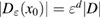
Consider an infinite homogeneous background acoustic medium occupying all of with d = 2 or 3 and characterized by the constant wave velocity c0 and the frequency . Let denote the background wave number in the background medium. Let D be an open, connected and bounded domain with Lipschitz boundary . We start by assuming that , where B1(0) is the unit ball around origin 0. This assumption is to separate the far-field from the near-field of the object D. Assuming that the minimal radius r = 1 among all bounding balls , we denote by the set of such shapes D. After rescaling by a size parameter this allows us to produce uniquely the geometric object located at a center


which is inscribed in the ball of radius ε and center x0. Now in our problem denotes the support of a scattering inhomogeneity characterized by a real constant (we will comment later on the case when n can be a function or complex) index of refraction n = c/c0 (with c denoting the wave velocity in ). In general, in the presence of absorption n is complex such that and . We extended n to by setting n = 1 in . The topology variables will be used for variation of inhomogeneities in our inverse scattering problem later on.


In the following formulation of the forward scattering problem and n are fixed. Considering an incident field that is a known solution of the unperturbed Helmholtz equation in called metaharmonic function [44] (typically such incident field is set to be a plane wave with incident direction and denoting the unit circle if d = 2 or the unit sphere if d = 3). Then the forward acoustic scattering problem under consideration is to find the total field


where the scattered field satisfies the Sommerfeld radiation condition (1c) uniformly in . The latter condition implies the existence of a far-field pattern [15] such that


The radiating fundamental solution Φ of the Helmholtz equation in is given by


where is the Hankel function of the first kind and order zero. The far-field pattern of , such that the asymptotic expansion


holds, is given by for , where the parameter is such that


It is well-known that the solution u of (1a)–(1c) satisfies the Lippmann–Schwinger equation (see e.g. [29, theorem 6.8])

where the volume potential

defines the bounded linear operator (see [29, section 6.2]) with the operator norm


If implying a contraction mapping, then from (5) it yields the convergent Neumann series for the solution

The far-field pattern of the scattered field corresponding to (1a)–(1c) admits the expression


For the following consideration we introduce the Herglotz operator defined as

Note that Hg is an entire solution to the Helmholtz equation. For a given geometry we denote by its restriction

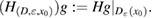
The L2-adjoint Herglotz operator is given by

Then from (9) and (11) it follows the following expression for the far-field pattern of the scattered field corresponding to (1a)–(1c)


which will be used later on in the proof of theorem 1.
The inverse scattering problem under consideration is to find the location x0 of the inhomogeneity from a knowledge of measured far-field pattern corresponding to a few (to become precise later) incident waves without knowing its refractive index n. Next we derive a stable criteria for solving this inverse problem based on an optimality condition associated with the topology sensitivity functional.

3. Optimality condition for the topological sensitivity functional
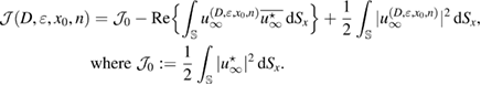
Let the true (unknown) inhomogeneity be with refractive index and let us denote the corresponding far-field measurement due to a given incident field by . The latter is what we measure. For variation of the topology, a trial inhomogeneity with a trial refractive index n is put in the background medium. This constitutes a family of solutions of the forward problem (1a)–(1c) for the same incident field. We denote by the corresponding far field pattern. To identify the unknown inhomogeneity, we set the least square L2 cost functional of the misfit far-field patterns by


which should be minimized over the trial variables. This minimization problem reads: find true variables such that


We say that the measurement is feasible with respect to the quadruple , if the solution of the corresponding forward problem obeys exactly this far-field pattern


In the feasible case (15), the trivial minimum in (14) is attained. Note that for uniqueness results on determining the support of the inhomogeneity (of polygonal shape or a ball) with one incident wave we refer to [16] and references therein.

Now we formulate the zero-order necessary optimality condition for (14), which is derivative-free.
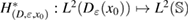
Theorem 1. Assume that and the measurement is feasible. Then the following necessary optimality condition for (14) holds


where the Herglotz operator H is defined in (10), is the solution of the forward scattering problem (1a)–(1c) for the true inhomogeneous medium, and the constant is given in (4).


Proof. For the feasible measurement , after multiplication with the complex conjugate of a test function u and integrating over the unit ball boundary , the identity (15) takes the following weak form


for all test-functions .

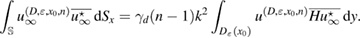
Next we insert in (17) with the adjoint Herglotz operator defined in (11) and use the integral representation (9) for the far-field pattern to derive from (17) that
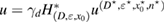


Using the identity (see [5, lemma 1]):

and interchanging the order of integration we arrive at
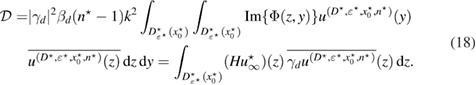
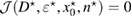
Since , then in the first equation in (18), which implies that the imaginary part of is zero, and the second equation in (18) after complex conjugation follows (16), thus proving the assertion of the theorem. □


Note that the factor is real-valued in 3d, and hence it can be omitted from formula (16) in three dimensions.

Remark 1. The weak variational form of the optimality condition (17), compared to its strong form (15), could potentially be used, by playing with test-functions, in order to seek other zero-order necessary optimality conditions in minimizing the least square L2 cost misfit functional for given measurements.
Next we apply to the necessary optimality condition (16) the asymptotic argument as , i.e. the volume of the support of the inhomogeneity becomes arbitrarily small.

4. Asymptotic optimality condition
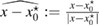
In order to arrive at an optimality condition that can be applied to solve the inverse problem we employ the topology asymptotic analysis using near-field expansions. To this end, in we assign to the center of the inhomogeneity a local d-dimensional coordinate system with the radial coordinate and d − 1 angular coordinates, i.e the polar coordinates in 2d, and the spherical coordinates in 3d. Furthermore denotes d-coordinate on the unit ball boundary centered at .


Since is an entire solution of the Helmholtz equation in an arbitrary ball of radius R > 0 and center , it has the following expansion in the two-dimensional case (see [15, section 3.4]):


with the Fourier coefficients and the Bessel functions of order , whereas in the three-dimensional case (see [15, section 2.4]):


where , are the spherical harmonics, and are the spherical Bessel functions of order .


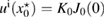
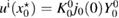
From (19) we find that , whereas from (20) that , and in the both 2d and 3d cases, we infer the following near-field asymptotic representation of as


The Herglotz wave defined in (10) is an entire solution of the Helmholtz equation, thus it satisfies


Hence, for a small size parameter , (21) and (22) in the ball of radius imply that in it holds


The Born approximation stated in (7) and (8) now takes the form

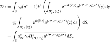
Plugging the asymptotic relations (23) and (24) into the necessary optimality condition (16) proves straightforwardly the following theorem.
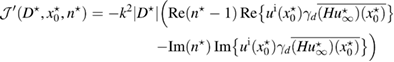
Theorem 2. Assume that and the measurement is feasible. Then the necessary optimality condition (16) has the asymptotic form as :


Remark 2. The principal asymptotic term in (25) is determined by the incident field which is an entire solution to the Helmholtz equation and by the Herglotz wave function which density is the far-field measurement corresponding to this incident field.


We give an interpretation of formula (25) from the point of view of a topological derivative following [5]. To this end, we first decompose the cost functional in (13) as follows

Interchanging the order of integration and using (9) implies that
Applying the asymptotic formula (23) and (24) we now get the two-parameter -asymptotic representation of the cost functional


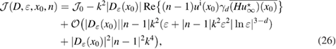
where we have assumed that according to (8), and for the Hausdorff measure of the sets in .


Hence from (26) it follows the following expression of the topological derivative of :

Theorem 3. For fixed and we have that


Now let be the solution of the topology optimization problem (14). This means that the optimal value of the cost functional in (26). Varying the imaginary part of the optimal refractive index , we observe that the second term in the expression of the topological derivative from (27):


should be asymptotically zero according to theorem 2.
Based on theorem 2, we suggest to consider the real-valued imaging operator which, for given incident field is defined over the space of far-field patterns as follows


Due to (25), the continuous function possesses the property that asymptotically at the center of the unknown inhomogeneity . This implies that the zero-level set of contains (asymptotically) the inhomogeneity center :


Consequently, this suggest the test center is looked for (asymptotically) as the intersection point of d zero-level sets:


from different far-field measurements in d dimensions.

An asymptotic model of similar type as (30) was justified numerically in [32] for the imaging of impedance obstacles from boundary measurements in the near-field. It was shown to produce high-accuracy and stable identification results. In the next section, we show that this is the case for the inhomogeneous media too, namely (30) produces accurate and stable location of the inhomogeneity center from far-field measurements.
5. Numerical examples
5.1. Direct scattering problem
For computation of the solution of the forward scattering problem (1a)–(1c) we use its equivalent formulation in the form of Lippmann–Schwinger integral equation (5) with the weakly singular operator given in (6).

Without loss of generality, let be the finite computational test domain, that is the unit square in 2d and the unite cube in 3d, containing a homogeneity with a refractive index n. For a fixed mesh size , we denote the nodal points of the uniform grid (quadrilateral in 2d and polyhedral in 3d) in the closure by


Based on the fast solver from [43], we apply to (5) and (6) the following formula of numerical integration over :

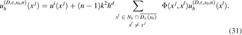
The system matrix of (31) is sparse and non-symmetric. In [43, theorem 1], for fixed k = 1 and sufficiently small h, the unique solvability of the linear system (31) is established and in addition the -error estimate in the max-norm:


is proved. We examine numerically the error defined in (32) with respect to the product kh following [23]. The error is presented here for a typical numerical test in 2d. In this example, the inhomogeneity D is circle-shaped of size centered at x0 = (0.25,0.75), with the complex-valued refractive index , which is illuminated in the direction of by the plane wave with . The wave numbers are taken in the range of , and the mesh size . Since there is no any analytical solution available, we substitute the exact solution with the discrete solution calculated on the finest mesh with . In figure 1 the values of are depicted in dependence on the parameter kh, respectively:


![$k\in[2, \dots, 2^7]$](https://content.cld.iop.org/journals/0266-5611/34/3/035009/revision2/ipaaa997ieqn144.gif)
![$h\in[2^{-7}, \dots, 2^{-3}]$](https://content.cld.iop.org/journals/0266-5611/34/3/035009/revision2/ipaaa997ieqn145.gif)


- for fixed waves numbers when varying h in plot (a),
- for fixed mesh sizes when varying k in plot (b),
- for fixed when increasing k in plot (c).


Figure 1. The Error in (32) for the discrete solution of the Lippmann–Schwinger equation with respect to kh.
Download figure:
Standard image High-resolution imageWe observe that the discretization error in plots (a) and (b) of figure 1 is super-linear, and the pollution error (see the explanation in [23]) in plot (c) is moderate. From our numerical tests we confirm these features of the error for wave numbers k and mesh sizes h chosen such that .


In the far-field, one needs to discretize the unit circle in 2d or the unit sphere in 3d. Here M denotes the finite set of nodal points on the unit ball boundary in . Then the discretization of the far-field (see [43, section 3.5]) for is given by


Finally, for far-field measurement given at nodes , the Herglotz operator (10) can be discretized for as


Proper weights in (34) should be determined depending on meshing of . For example, on the unit circle in 2d we use equidistant nodes with for and fixed , then all weights . For the uniform latitude-longitude grid on the unit sphere in 3d such that with as above and for and fixed , we use the cubature formula based on the trapezoidal rule with the positive weights


5.2. Optimality-based-imaging of the center
In our numerical tests, in order to compute the imaging function (28) for identifying the center of a given inhomogeneity with support and refractive index , we use the numerical solution given by (31), in order to synthesize the discrete far-field measurement according to formula (33) and the corresponding Herglotz wave as per (34). In this setting from the discrete far-field measurement given at nodes and the incident field known at mesh points , depending on these two grids we calculate the discrete imaging function according to (28) for as follows


In the following we show some examples as proof of concept showing the identification of the inhomogeneity center based on the imaging function from (35).
In figure 2 we present the result for the case when the inhomogeneity is L-shaped of size centered at , with the real-valued refractive index . The computation is done over the unit square with the mesh sizes , and equidistant points on the unit circle (relatively few measurement points).


Figure 2. Identification of the center of L-shaped inhomogeneity from two far-field measurements in 2d. The wave number here is k = 1.35.

Download figure:
Standard image High-resolution imageTwo far-field patterns and correspond to the case when the inhomogeneity is illuminated by a plane wave with in the direction of and , respectively. Plots (a) and (b) depict the corresponding imaging functions and together with the zero-level sets and , which form straight lines crossing the inhomogeneity. The zero-level sets are depicted also in the computational test domain Ω in the plot (c), their intersection point:


is unique and close (to become quantitative measure later) to the test center . Moreover, exactly, if the size is sufficiently small such that . Here zero-level sets are utilized numerically using the narrow strip technique, see e.g. [33]. More specifically, in a narrow strip of nodes where changes its sign, we interpolate the discrete imaging function by multivariate polynomials which are bilinear in 2d (respectively, trilinear in 3d). This technique determines zero-level sets on a local grid which maybe finer than Nh in the whole computational domain. Typically, we set it to in the narrow strip. It is important to stress that the wave number is chosen small: k < k1 below the threshold ( in this example) when the reconstruction starts to break down. We observe that starting from approximately k = 1.35, there appear multiple lines of zero sets (see the line in the upper right corner in figure 2) and they grow when increasing k.


In figure 3 we show the same experiment for k = 2.25. In this case the level curves are not necessary lines any longer and there appear multiple intersection points. A possible remedy of this situation is to use an additional measurement, which confirms the true intersection point as illustrated in figure 3 for three measurements with , , and .


Figure 3. Example of multiple intersection points of the zero-level sets for large wave numbers. The wave number here is k = 2.25.
Download figure:
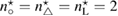
Standard image High-resolution imageSince the asymptotic expansions in section 4 are carried out in the near-field of the inhomogeneity center , the imaging function cannot distinguish between multiple inhomogeneities put in the test domain. In figure 4 we give an illustrative example of triple inhomogeneities: the ball-shaped of size centered at with the refractive index , the triangle-shaped of size centered at with , and the L-shaped of size centered at with . Here the wave number k = 1 and three plane waves propagate along the directions of . From figure 4 we conclude that the zero-level sets intersection is closer to those inhomogeneity mostly contrasting with the background refractive index n = 1 (here the triangle-shaped inhomogeneity). While the remaining inhomogeneities can be considered as a perturbation of the homogeneous background medium. If the refractive indexes all are equal here, then the intersection is close to a mass-center of the geometric set of inhomogeneities in the test domain, compare figures 4 and 5.


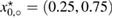


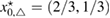


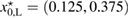


Figure 4. Example of three far-field measurements of the contrast obstacle for triple inhomogeneities. The refractive indexes are different here , , and .


Download figure:
Standard image High-resolution image
Figure 5. Example of three far-field measurements of the mass-center for triple inhomogeneities. The refractive indexes are the same here .
Download figure:
Standard image High-resolution imageWe carried out a series of numerical tests for inhomogeneities of various shapes, namely L-shape, ball, triangle, point (in the last case ), varying the location in the test domain , illumination directions, the wave number, and the mesh sizes in the range of . Although our theory covers only real refractive index we test our imaging criteria (36) for refractive index with small imaginary part. In the following we report our numerical findings. Figure 6 presents how the error of center-identification depends on various parameters explained below. This is a 2d study.


![$h, h^\star\in[2^{-6}, \dots, 2^{-3}]$](https://content.cld.iop.org/journals/0266-5611/34/3/035009/revision2/ipaaa997ieqn230.gif)


- (i)The intersection point of zero-level sets of the imaging function, calculated for a number of different measurements not less than the dimension, is uniquely determined for the wave numbers with depending on the problem parameters.
- (ii)The identification error depends super-linearly on the mesh size of the grid used to synthesize the far-field measurement . It is not sensitive to the mesh size used for the imaging function, and to the grid M if chosen uniformly on the unit circle with nodes.
- (iii)If the test center coincides with a node of the grid , this leads to the better identification result than . For comparison see the two curves of the error depicted in the plot (a) in figure 6 in terms of the size .
- (iv)The identification error drops super-linearly with respect to decreasing the size of the unknown inhomogeneity as shown in figure 6(a). For comparison, the error-curves for the ball of size and for the equilateral triangle of size are presented through the other plots (b)–(d).
- (v)
- (vi)In figure 6(d) the stability of the identification is tested with respect to a Gaussian noise with the standard deviation computed over 200 realizations of the far-field measurement. The error here is less then for .


![${\rm Re}(n^\star)\in[0.01, 100]$](https://content.cld.iop.org/journals/0266-5611/34/3/035009/revision2/ipaaa997ieqn248.gif)

![${\rm Im}(n^\star)\in[0, 0.1]$](https://content.cld.iop.org/journals/0266-5611/34/3/035009/revision2/ipaaa997ieqn250.gif)


Figure 6. Tests of the error in the identification of the inhomogeneity center.

Download figure:
Standard image High-resolution imageRemark 3. We list some conclusions obtained from our two-dimensional numerical study:
- (1.)Numerical examples demonstrate high-precision of the identification of the center of the inhomogeneity as well as stability with respect to discretization and noise.
- (2.)
Finally, in figure 7 we show a three-dimensional example, namely the identification of the center of a ball-shaped inhomogeneity of size centered at with the refractive index . Computations are done for the mesh sizes over the uniform grid with longitude and latitude lines on the unit sphere. The inhomogeneity is illuminated by 3 plane waves with and in three perpendicular directions of , , and . In the plots (a)–(c) we show the corresponding zero-level sets forming planes which cross the inhomogeneity, and their intersection point coincides with the center of the ball as shown in the plot (d).

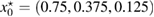


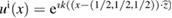


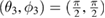


Figure 7. Identification of the center of ball-shaped inhomogeneity from three far-field measurements in 3d.

Download figure:
Standard image High-resolution image
Acknowledgments
FC is supported by AFOSR grant FA9550-17-1-0147, NSF Grant DMS-1602802 and Simons Foundation Award 392261.
VK is supported by the Austrian Science Fund (FWF) project P26147-N26: 'Object identification problems: numerical analysis' (PION) and the Austrian Academy of Sciences (OeAW).