

Abstract
An inverted pendulum can be stabilised by hand or by a high frequency sinusoidal vertical oscillation of the bottom end or by feedback control if a horizontal force is applied at the bottom end. The pendulum is unstable if a sinusoidal force is applied in a horizontal direction at the bottom end. It is shown in the present paper that an inverted pendulum can be stabilised if a low frequency horizontal force is applied at the bottom end to right the pendulum after it falls through a small angle. The technique requires a measurement of the fall angle but is not sensitive to the actual fall angle. The technique represents a simple example of feedback control and is more easily understood than vertical oscillation of the bottom end.
Export citation and abstract BibTeX RIS

Original content from this work may be used under the terms of the Creative Commons Attribution 4.0 licence. Any further distribution of this work must maintain attribution to the author(s) and the title of the work, journal citation and DOI.
1. Introduction
An inverted pendulum or a uniform rod supported at its bottom end on a horizontal surface will fall quickly onto the surface if released from rest. However, a rod or an inverted pendulum can be stabilised in a near vertical position if the surface itself oscillates in a vertical or horizontal direction in an appropriate manner. The stability problem has been studied extensively since the 1960s and is related to the problem of balancing an inverted stick on one finger or in the palm of the hand [1–3]. Early theoretical studies of the stability problem focussed on sinusoidal excitation of the bottom end of an inverted pendulum [4, 5], indicating that vertical or horizontal excitation should both stabilise the pendulum. Experiments with vertical excitation were subsequently reported [6, 7], but not with horizontal excitation.
Sinusoidal excitation of an inverted pendulum in the horizontal direction was later found to be unstable after several stable cycles of oscillation [8]. However, feedback control has been used by engineers to stabilise an inverted pendulum by mounting it on a cart that moves horizontally in response to the sensed parameters of the pendulum. It is still an active area of research, referred to as the cart and pole task or system, and has led to practical applications such as the self-balancing Segway personal transporter. A history of research into inverted pendulum problems is given by Lundberg and Barton [9].
In 1970, Kalmus [6] found that an inverted pendulum could be stabilised by subjecting the bottom end to a series of short vertical impulses rather than using sinusoidal excitation. The claimed advantage was that it is more easily and more intuitively understood. A similar technique is analyzed in the present paper for the case of horizontal excitation. The main difference is that in the case of vertical excitation there is no need to monitor the angular displacement of the pendulum, whereas the angular displacement needs to be monitored if horizontal excitation of an inverted pendulum is used to stabilise the pendulum in a near vertical position. On the other hand, sinusoidal horizontal excitation can be used to stabilise a pendulum in a near horizontal position, without the need to monitor the angular displacement [10].
Feedback control of an inverted pendulum is now a standard topic for undergraduate engineering students. The simplified version described in the present paper would be a suitable topic for physics students, and also for biomechanics students since the same control method is commonly used to stabilise motion of the human body.
2. Theoretical model
The geometry of an inverted pendulum or rod is shown in figure 1. The pendulum is inclined at an angle θ to the vertical, and the bottom end rests on a horizontal surface at x coordinate xP and y coordinate yP = 0. The center of mass, G is located at a distance h from the bottom end, with coordinates  and
and  . The angle θ is taken to be positive if xG
> xP or negative if xG
< xP. Released from rest, the pendulum will fall onto the horizontal surface at angular velocity ω = dθ/dt and the center of mass will translate in the x direction at velocity vx
= dxG
/dt.
. The angle θ is taken to be positive if xG
> xP or negative if xG
< xP. Released from rest, the pendulum will fall onto the horizontal surface at angular velocity ω = dθ/dt and the center of mass will translate in the x direction at velocity vx
= dxG
/dt.
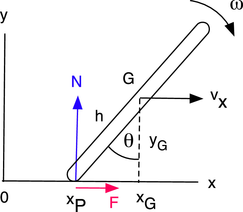
Figure 1. Geometry of an inverted pedulum. G is the center of mass.
Download figure:
Standard image High-resolution imageThe bottom end of the pendulum is subject to a vertical force N and a horizontal force F. The bottom end could pivot about a fixed point, or it could slide forwards or backwards depending on the magnitude of F. If m is the mass of the pendulum then the equations of motion are


and

where Icm is the moment of inertia of the pendulum for rotation about an axis through its center of mass. In terms of the angle θ,


and

where aP = d2
xP/dt2 and I0 = Icm + mh2 is the moment of inertia about an axis through the bottom end of the pendulum. A horizontal force at the bottom end of the pendulum is needed to accelerate G in the x direction, arising from static friction if the bottom end remains at rest, or sliding friction if the bottom end slides backwards or forwards, or from an external force if the bottom end is pushed forward or pulled backward. Equation (6) indicates that the pendulum can stop falling and start to rise if  . As described below, that condition can be satisfied if an external horizontal force is applied after the pendulum starts falling.
When balancing a rod using one finger on the bottom end, the bottom end needs to be relocated under the center of mass if the rod starts to fall. If that is done while the rod is falling, the rod will have sufficient angular velocity to keep falling, at a smaller rate. The bottom end needs to be moved past the center of mass to reverse the direction of the fall, then relocated under the center of mass when the angular velocity decreases to zero. That is how a person can balance a rod and how the cart and pole problem is solved. One might therefore expect that sinusoidal motion of the bottom end in a horizontal direction should also work, as claimed in [4] and [5].
3. Sinusoidally driven pendulum
A numerical solution of equations (4)–(6) is shown in figure 2 assuming that  and
and  for a uniform rod of mass m = 0.5 kg and h = 0.6 m, with θ(0) = 0, ω(0) = 0.1 rad s−1, x0 = 0.2 m and ω0 = –1.843226 rad s−1. The numerical solutions were obtained using both a second order finite difference method and a second order predictor-corrector method, with essentially the same results. Solutions are very sensitive to each of these parameters, giving a stable result for one or two cycles before becoming unstable. The same problem was encountered in [8], regardless of the numerical method used to solve the problem. The authors concluded that 'the origin of the physical instability requires further elaboration'. The solution for a falling rod hinged at the bottom end shows that θ increases exponentially with time [11] so any small numerical or physical departure from the ideal driven solution is likely to lead to instability.

Download figure:
Standard image High-resolution imageDespite the result in figure 2, a rod can be balanced in a horizontal position when driven by a sinusoidal horizontal oscillation of the pivot end [10]. A numerical solution of equations (4)–(6) is shown in figure 3 for the same conditions as figure 2 but with θ(0) = 90° instead of θ(0) = 0, and with ω(0) = 0.1 rad s−1, x0 = 0.2 m and ω0 = 100 rad s−1. The solution is essentially the same as that when balancing a vertical inverted rod by oscillating the bottom end in a vertical direction. A nice demonstration and explanation of the effect can be found on YouTube at https://youtu.be/5uZdwxbLdJ8.

Download figure:
Standard image High-resolution image4. Impulsive drive
An alternative solution of equations (4)–(6) for an initially vertical pendulum is shown in figure 4, assuming that aP = 5 m s−2 if θ > 5°, aP = −5 m s−2 if θ < − 5° and aP = 0 if −5° < θ < 5°. The same pendulum as that in figure 2 was allowed to fall freely from the vertical by up to 5°, then the bottom end of the pendulum was accelerated at a constant rate in the direction of the fall to stop and reverse the fall. The stability of the pendulum was not sensitive to any of these parameters when driving the pendulum using this technique, and the pendulum remained stable for at least 20 cycles. Solutions with more than 20 cycles were not investigated. Similar results were obtained with other values of aP between 1.8 and 20 m s−2, with other values of ω(0) between 0.05 and 1.2 rad s−1 and with other values of the permitted incline angle, θ.

Figure 4. Solution of equations (3)–(6) with horizontal impulse excitation, assuming that vx (0) = –0.255 m s−1, ω(0) = 0.1 rad s−1, and ∣aP∣ = 5 m s−2 when ∣θ∣ > 5°.
Download figure:
Standard image High-resolution imageThe solution in figure 4 is stable and periodic but the whole pendulum undergoes large excursions, back and forth in the x direction, while θ oscillates between −5.5° and +5.5°. Large excursions of the center of mass arise since the net force at the bottom end is enhanced when the external force is applied, and the force at the bottom end does not reverse direction until θ decreases to zero, as shown in figure 4(a). The sign and magnitude of the excursions depend on the initial value of vx (0), which was chosen as −0.255 m s−1 so that the excursions would be approximately symmetrical about xG = 0. The excursions were not exactly symmetrical since the time at which the external force was applied depends slightly on the step size used in the numerical integration. The step size was 0.002 s in figure 4. Much smaller excursions of the bottom end of the pendulum arise if the variations in θ are limited to say ±1° before the external horizontal force is applied, since the magnitude of the required external force can then be reduced.
Other stable solutions with horizontal drive can be obtained by ensuring that  when θ is small and that
  when θ exceeds some nominal value. For example, stable solutions can be obtained if
  , giving dω/dt = 0 when θ = 1.15° from equation (6), and dω/dt < 0 when θ > 1.15°. In that case, aP increases smoothly from zero when θ = 0 to a maximum when θ > 1.15°, rather than increasing suddenly, as it does in figure 4. A typical result is shown in figure 5, for the same pendulum as that in figure 2, assuming that ω(0) = 0.1 rad s−1 and dω/dt = 0 when θ = 1.15°.

Figure 5. Solutions of equations (4)–(6) with horizontal impulse excitation, assuming that vx (0) = −0.147 m s−1, ω(0) = 0.1 rad s−1, and dω/dt = 0 when θ = 1.15°.
Download figure:
Standard image High-resolution image5. Discussion
The essential physics of the horizontally driven vertical pendulum is described by equations (3) and (6) Without intervention, a falling rod will fall at a rate that increases with time since the torque acting on the rod due to the normal reaction force increases with time, while the opposing torque due to the friction force decreases with time. A rod of length say 1 m will take about 0.6 s to fall into a horizontal position, depending on its initial inclination to the vertical. If an external horizontal force of sufficient magnitude and duration is applied to the falling rod, the direction of the torque can be reversed, in which case the rod can stop falling and begin to rise. If the rod swings past the vertical position then it will start falling in the opposite direction, so the external force needs to decrease to zero before that happens. However, the rod can be allowed to swing past the vertical position due to its momentum, in which case an external horizontal force in the reverse direction can then be applied to stop the rod falling too far in the reverse direction. A periodic oscillation of the rod will arise if a periodic external horizontal force is applied for a short time each time the rod falls through a given angle past the vertical, as shown in figure 4. The period of oscillation of the rod will then be the same as the period of the external force.
An inverted pendulum can therefore be stabilised by applying a periodic force in the horizontal direction at the bottom end of the pendulum, with a slight disadvantage that the whole pendulum moves back and forth in the horizontal direction. Nevertheless, a similar technique is used to advantage by people who skate on ice or on roller skates. Skaters lean to the left and right periodically, and arrest their fall by pushing hard on the skate when the lean angle exceeds about 10 or 20 degrees. The action is depicted in figure 6, indicating that the center of mass of each skater is well to the left of the point of support. Between each push, the skater travels at roughly constant speed at an angle to the mean forward direction of motion, then changes direction during each push, and transfers weight onto the other skate, in a manner similar to that shown in figure 4(b). The center of mass of the skater translates from side to side, like the inverted pendulum in figure 4, while the skater moves forward at approximately constant average speed. The push force applied by the skater is not exactly periodic, and does not need to be, since the push force and duration needs to be adjusted by the skater to vary the speed and direction of travel around the skating track [12].

Figure 6. (a) An ice skater and (b) an in-line roller skater both falling to the left and both skating at about 50 km hr−1.
Download figure:
Standard image High-resolution image
A similar result is obtained when a person walks in a straight line [13]. When the left foot lifts off the ground and moves forward, the center of mass rotates forward about the right foot like an inverted pendulum. The fall is arrested by planting the left foot on the ground and pushing forward and downward on the ground. In that case, the center of mass moves forward at a constant average speed, rather than oscillating back and forth at zero average speed as in figure 3(b). Walking on a treadmill would achieve the latter result.
6. Conclusion
It is not possible to stabilise an inverted pendulum using sinusoidal horizontal oscillation of the bottom end without some form of feedback control. A simple technique is described in the present paper where a horizontal restoring force is applied each time the pendulum falls through a given angle. That technique is used by people to prevent themselves falling forwards or sideways, given that activities such as walking or running or skating can be described in terms of inverted pendulum models.
Data availability statement
All data that support the findings of this study are included within the article (and any supplementary files).
Author declaration
The author has no conflicts to disclose.