

Abstract
In this paper a novel highly birefringent neodymium-doped microstructured optical fiber is presented. The modal properties of the structure are analyzed numerically using a fully vectorial finite difference method. Results obtained are compared with experimental near-field measurements. The emission properties of the structure have also been investigated. The emission cross-sections at 900, 1064 and 1334 nm have been measured. Laser action has been achieved at a wavelength of 1064 nm in the simplest configuration, based on Fresnel light reflection at both ends of the fiber. The optical conversion efficiency was 9% and the slope efficiency reached 16%. A laser configuration with an external fiber Bragg grating has also been studied; promising results obtained for this configuration suggest that such a laser can find applications in sensing.
Export citation and abstract BibTeX RIS
1. Introduction
Microstructured fiber (MOF) optics technology opens new opportunities for the design of special fibers with an improved range of parameters when compared with the traditional step index optical fiber. With an appropriate design a microstructured fiber with single-mode operation, anomalous dispersion or nonlinearity control can be realized [1–3]. Microstructured fibers have also found applications in fiber laser technology due to the great flexibility in shaping photonic crystal waveguide structures. Based on these properties one can design, for instance, a large mode area (LMA) fiber for a high brightness fiber laser or a small core fiber for telecommunications or sensing applications [4–7]. One of the main types of optical fiber used in both laser and sensor applications is the highly birefringent fiber. Several types of highly birefringent fiber can be distinguished. One type is based on introducing a mechanical stress into the cladding region (using materials with a higher thermal expansion coefficient than silica glass), e.g. PANDA and bow-tie fibers [8–10]. Another type, investigated in this work, is realized by introducing an asymmetric air hole lattice pattern into a MOF. This second approach gives similar, or even higher, values of the modal birefringence when compared to commercially available fibers that are based on stress applied parts (SAP) [11]. However, the main advantage of using the second approach is the very low temperature sensitivity compared to highly birefringent fibers based on SAP; the reason for this is that MOFs are only made from one material (silica) and air. Consequently, HB MOFs are better candidates for sensor applications than SAP fibers.
Using a highly birefringent fiber in a laser cavity allows the construction of a single polarization fiber laser or a multi-wavelength fiber laser [12–17]. The insensitivity of the MOF opens the way to the realization of lasers with better stability than that achievable with a SAP fiber. Single polarization and stability are also required for the construction of pulsed fiber lasers. Furthermore, a fiber with an inscribed fiber Bragg grating (FBG) can be a very good sensor, because the difference in the wavelengths of the laser spectrum peaks is equal to the birefringence of the fiber. The factors that change the birefringence of the fiber (i.e. mechanical strain, pressure, elongation) can thus be related to the wavelength difference between the laser peaks [18]. In this paper we present a specially designed and manufactured neodymium-doped highly birefringent microstructured fiber (Nd-HB-MOF). The emission spectra of the doped fiber are measured. The electromagnetic field distributions of the MOF structure are calculated using a fully vectorial finite difference method. Laser action in a cavity based on the Fresnel reflection between the air and glass at both fiber ends is demonstrated. A laser cavity based on a FGB and Fresnel reflection has also been presented.
The results are presented as follows. In section 2 the procedures used for the fabrication and characterization of the Nd-HB-MOF are described. In section 3 we present results on the construction of a Nd-HB-MOF laser in a linear configuration. Conclusions are drawn in section 4.
2. Characterization of the Nd-HB-MOF
2.1. Fabrication of the photonic active fiber
The cross-sectional structure of the manufactured microstructured optical fiber is presented in figure 1. This MOF was specially designed for FBG inscription. The limited number of air holes minimizes scattering, diffraction and defocusing of the FBG laser writing beam [11, 19]. The fiber was made using a stack-and-draw technique. The fiber preform was created by stacking capillaries around a solid rod. The doped core was produced using a conventional modified chemical vapor deposition technique. The active core was doped with 1300 ppm of neodymium with aluminum and germanium co-doping. The co-doping elements are used to compensate for the change in the refractive index that is introduced when doping the core with neodymium ions. Co-doping with germanium gives the possibility of writing FBGs (fiber Bragg gratings) in this structure. The average refractive index of the active preform was similar to the refractive index of pure silica.
2.2. Modal properties of the Nd-HB-MOF
The basic modal properties of the presented structure have been calculated using a commercially available finite difference solver [20]. We used a simulation area of 46 μm × 27 μm with perfectly matched layer (PML) boundaries. The grid spacing was chosen to be 0.05 μm in the fiber core area and 0.1 μm in the rest of the simulation area. The cross-section of the Nd-HB-MOF analyzed using the finite difference method is presented in figure 2. Based on the electromagnetic simulation, the phase modal birefringence, the effective index and the mode field area have been calculated. Figure 3 presents the calculated phase modal birefringence as a function of the wavelength. The definition of the phase modal birefringence used in these calculations is

where βx and βy are the propagation constants of the modes polarized in the x- and y-directions respectively [21] while λ is the free-space wavelength. The calculated phase modal birefringence for this fiber is equal to 1.19 × 10⁻⁴ at a wavelength of 808 nm and 2.67 × 10⁻⁴ at a wavelength of 1064 nm. The range of values of phase modal birefringence obtained for the Nd-HB-MOF is comparable to the values quoted for commercially available highly birefringent fibers based on SAP [11]. Figure 4 presents the calculated effective indices of the x- and y-polarized fundamental modes as a function of the wavelength. The calculated effective mode areas for the x- and y-polarized fundamental modes are presented as a function of wavelength in figure 5. The mode field areas for the x- and y-polarized fundamental modes at 1064 nm are equal to 13.27 μm2 and 12.79 μm2 respectively. These results indicate that for the MOF studied the mode area is less dependent on wavelength than in comparable traditional fibers [22]. This feature is advantageous in a fiber laser because the overlap integral for the pump and the signal can be higher than in a conventional rare earth doped fiber.
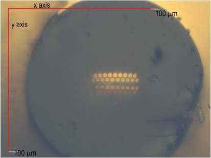
Figure 1. Cross-section of the Nd-HB-MOF.
Download figure:
Standard image High-resolution image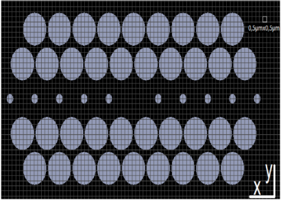
Figure 2. Cross-section of the Nd-HB-MOF as analyzed using the finite difference method. Lilac regions indicate the air holes and black regions are the silica.
Download figure:
Standard image High-resolution image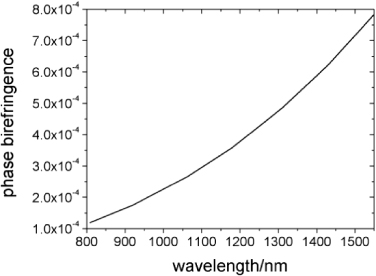
Figure 3. Calculated phase birefringence of the Nd-HB-MOF as a function of wavelength.
Download figure:
Standard image High-resolution image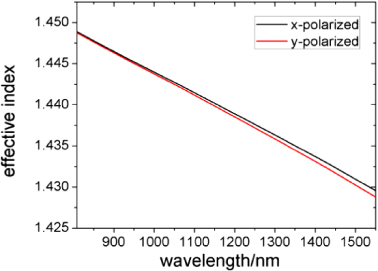
Figure 4. Effective indices of the x-polarized (black) and y-polarized (red) fundamental modes of the Nd-HB-MOF as a function of wavelength.
Download figure:
Standard image High-resolution image
Figure 5. Effective mode area of the x-polarized (black) and y-polarized (red) fundamental modes of the Nd-HB-MOF as a function of wavelength.
Download figure:
Standard image High-resolution image2.3. Near-field measurements and calculations
The mode field profiles in a MOF are not clearly defined as in a typical cylindrical fiber. The modal field that is guided inside the MOF depends on the parameters of the lattice structure. Hence, it is important to know the exact mode field profile of a MOF. The calculated field intensity profile for the x polarized fundamental mode at a wavelength of 1064 nm is presented in figure 6.
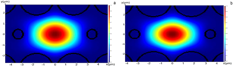
Figure 6. Calculated field intensity profile for the x-polarized fundamental mode (a) and the y-polarized mode (b) at a wavelength of 1064 nm.
Download figure:
Standard image High-resolution imageThe mode field intensity has been also measured experimentally at the signal wavelength of 1060 nm. This measurement was performed using a Thorlabs BP 104 Slit Scanning Beam Profiler and the obtained mode field profile is shown in figure 7. The mode has a nearly elliptical spot shape, which is typical for the fundamental mode. The elliptical shape of the beam is caused by breaking the rotational symmetry of the MOF structure. The experiments show that this mode is very robust, and no evidence of higher-order modes was observed even when changing the launching conditions. The measured modal distributions along the x- and y-axes closely follow a Gaussian (fit) profile.
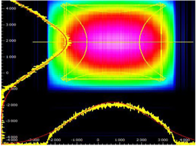
Figure 7. Measured mode field intensity at the signal wavelength (1060 nm). Horizontal and vertical line scans through the maximum intensity point (yellow lines) with Gaussian fits (red lines).
Download figure:
Standard image High-resolution image2.4. Emission cross-section measurements
The emission spectrum from a 1 m length of Nd-HB-MOF was measured. Light from a single-mode laser diode working at a nominal wavelength of 808 nm was introduced into the Nd-HB-MOF using bulk optics. The launching equipment consisted of a fiber collimator (f = 11 mm and NA = 0.25) and a microscope objective with magnification ×40 and NA=0.6. Since the Nd-HB-MOF has a very small core, the coupling efficiency was low. The output spectrum was observed using an optical spectrum analyzer (OSA), Yokogawa AQ6370C. Based on this measurement the emission cross-sections at 900, 1064 and 1334 nm have been calculated using the Fuchtbauer–Ladenburg theory, see figure 8 [23]. The measured lifetime at 4F3/2 was equal to 450 μs, while the assumed branching ratios for the transitions 4F3/2→4I9/2, 4F3/2→4I11/2 and 4F3/2→4I13/2 are 60%, 39% and 1% respectively [24]. The calculated emission cross-section was 1.5 × 10⁻²⁰ cm2 at a wavelength of 900 nm, 2.18 × 10⁻²⁰ cm2 at 1064 nm and 0.139 × 10⁻²⁰ cm2 at 1334 nm. The results obtained are in good agreement with the results for silicate fibers quoted in the literature [24].
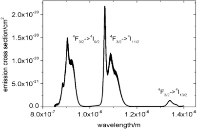
Figure 8. Measured emission cross-sections for the Nd-HB-MOF.
Download figure:
Standard image High-resolution image2.5. Lifetime measurements
The decay curve of the upper laser manifold 4F3/2 was measured using a pulse excitation at the wavelength 808 nm. The decay waveform was captured on a LeCroy 1 GHz oscilloscope. The characteristic lifetime was found by fitting a single exponential function to the measured waveforms. The measured lifetime was 450 μs ± 30 μs for pump powers in the range 3–10 mW. The measured decay profiles and fitting functions are presented in figures 9(a) and (b).

Figure 9. Decay curve with e-folding fitting of the 4F3/2 lifetime in the Nd-HB-MOF (a) on a linear scale and (b) on a logarithmic scale.
Download figure:
Standard image High-resolution image3. Experimental results for the Nd-HB-MOF fiber laser
The laser setup is presented in figure 10. Laser action was achieved experimentally in a simple configuration based on the Fresnel reflection at both ends of the fiber. The fiber was pumped by a single-mode pigtailed laser diode (LU0808M250). The diode FWHM was 0.5 nm and the peak wavelength was 808 nm. The Nd-HB-MOF fiber length was 15 m. The optimum fiber length has been found experimentally. We measured, at a fixed launched pump power, the output power for different fiber lengths of 1, 5, 15, 30 m. The best result was obtained for L = 15 m, for which around 90% of pump power was absorbed. Figure 11 shows the dependence of the laser output power on the launched pump power. The launched pump power was measured using a 5 cm length of the fiber with the same launching conditions. The laser threshold occurs for a launched pump power of around 18 mW. The maximum laser output power was 3 mW at 1064 nm for 33.83 mW of launched pump power. The measured optical conversion is therefore 9% and the slope efficiency equals 16%. The slope efficiency was measured using an optical power meter and a long pass optical filter with a cut on at a wavelength of 1030 nm. The laser light was passed through the optical filter in order to ensure that only the signal above 1030 nm was recorded. Figure 12 shows the laser spectra as a function of the launched pump power recorded using the OSA. A spectrum about 5 nm wide and with a difference of over 25 dB between the radiation peak and the background noise indicates that a lasing action is taking place. The laser action was observed at around 1064 nm. Figure 13 shows the laser spectrum in more detail around 1064 nm. This result indicates a multi-wavelength laser operation. The observed multi-wavelength operation was not stable and the output oscillated with time.
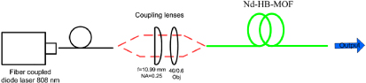
Figure 10. Laser configuration based on Fresnel reflection at both ends of the fiber.
Download figure:
Standard image High-resolution image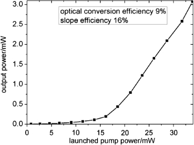
Figure 11. Output power as a function of launched pump power for a Nd-HB-MOF laser setup with Fresnel reflection at both ends of the fiber, from which the laser slope efficiency can be determined.
Download figure:
Standard image High-resolution image
Figure 12. Laser output spectrum recorded for different pump powers .
Download figure:
Standard image High-resolution image
Figure 13. Detail of the laser spectrum shown in figure 12 around 1064 nm.
Download figure:
Standard image High-resolution imageThe second laser configuration that has been studied is presented in figure 14. This laser configuration uses an external fiber Bragg grating (FBG) inscribed on a traditional photosensitive SM 780 fiber. The measured spectrum of the FBG grating is presented in figure 15. The properties of this FBG were measured by using neodymium ASE sources and an OSA (Yokogawa AQ6370C) with a spectral resolution of 0.02 nm. The FBG has 20 dB depth and 200 pm spectral width. The FBG was aligned to the end of the Nd-HB-MOF using a V-groove in a silicon wafer. The laser spectra recorded at the end of the FBG for different pump powers are shown in figure 16(a). Figure 16(b) shows the output spectrum in more detail, revealing that the laser action is multi-wavelength and that it occurs on the second dip of the FBG. The peak lasing wavelength was observed at 1064.16 nm. The laser threshold was recorded to be at around 15 mW of the launched pump power. The 3 dB bandwidth of the laser constructed is 0.5 nm. Experiments show that the laser has a signal-to-noise ratio of 24 dB at 1064.16 nm. Figure 17 shows the laser output recorded at the end of the FBG as a function of the launched pump power.

Figure 14. Experimental setup laser with an external FBG.
Download figure:
Standard image High-resolution image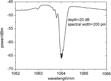
Figure 15. Spectrum of the FBG used in the configuration presented in figure 14.
Download figure:
Standard image High-resolution image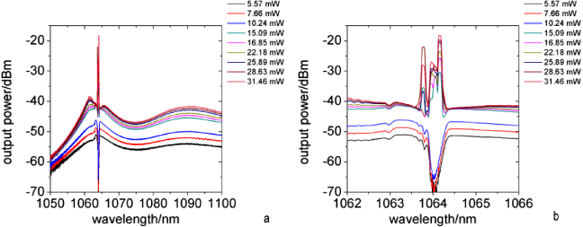
Figure 16. (a) The dependence of the output spectrum on the pump power; (b) the zoomed output spectrum.
Download figure:
Standard image High-resolution image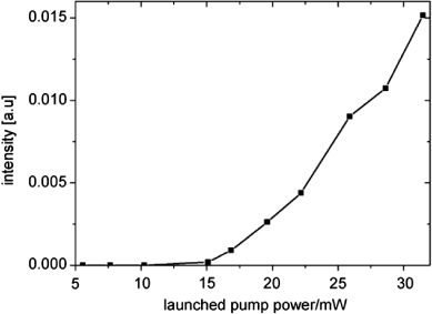
Figure 17. Laser output recorded at the end of the FBG with respect to the launched pump power.
Download figure:
Standard image High-resolution image
4. Conclusion
In this paper a novel highly birefringent MOF doped with Nd3+ is presented. The properties of this fiber have been investigated by a combination of simulation and experimental methods. Efficient laser operation has been achieved in the simplest resonator, based on Fresnel reflection from the ends of the fiber. Narrow band laser action was also achieved in a configuration with an external FBG placed at one end of the resonator.
These results suggest that Nd-HB-MOF is good candidate to achieve an efficient and stable laser. In order to obtain better results we plan in the future to directly inscribe the FBG on to the MOF structure. Fiber lasers based on a Nd-HB-MOF with an inscribed FBG can find potential applications in sensing equipment, such as interferometers and gyroscopes.
Acknowledgment
The work presented in this paper was supported by the statutory funds of the Institute of Telecommunication, Teleinformatics & Acoustics, Wroclaw University of Technology, Poland.