

Abstract
An efficient erbium doped superfluorescent fiber source (SFS) is proposed by comparing the different configurations in the C and L band regions. The flat spectrum of the source over a wide range is examined in various arrangements. The suggested array employed is based on loop mirror and double-pass bidirectional sources for making a flat and stable amplified spontaneous emission power. The maximum power of each of the two 980 nm laser diodes was optimized at 180 mW. Furthermore, the place effect of the laser diode's power near the output port was demonstrated for the first time. Finally, the optimum flattening manner of this ASE source was achieved in 185–50 mW pump powers and 32 mW total power over the 1525–1605 nm region (C+L band).
Export citation and abstract BibTeX RIS
1. Introduction
Wide band erbium doped superfluorescent fiber sources (SFS) have not only been used as a broadband light source for fiber optics gyroscopes (FOG) [1] but have also been studied for super-continuum generation [2, 3] and multi-wavelength fiber laser sources [4]. These sources based on erbium doped fibers (EDFs) have also been widely investigated due to their advantages, such as higher power conversion efficiency and lower threshold powers [5, 6]. Also, the use of SFS for EDF amplifier characterization and the wavelength division multiplexing (WDM) communication system have made it an important source [7]. These sources exhibit a unique combination of high efficiency, high spatial coherence, broad spectral emission and excellent long-term stability of the mean wavelength [8–10].
In general, there are four kinds of configurations for implementing amplified spontaneous emission (ASE) sources: single-pass forward (SPF), single-pass backward (SPB), double-pass forward (DPF) and double-pass backward (DPB). The characteristics of an Er-doped SFS are strongly dependant on the applied configuration. There are also some reports on SPF SFSs [11], but their insufficient output powers are rarely used [12]. The SPB configuration has been most commonly adopted for the C band ASE source owing to its ease of design and lower susceptibility to lasing [12, 13]. The double-pass forward (DPF) configuration is also suitable for an L band erbium doped fiber source [7]. Furthermore, an efficient SFS in DPB setup has been demonstrated to have a stable broadband spectrum with high output power [12, 14].
However, the development of fiber sensing based on fibre Bragg grating (FBG) technology and the application of WDM technology achieving multi-signals power equalization is also important for long-distance transmission, amplification, and demodulation of FBG sensing signals. So, the broadband SFS with a high flatness spectrum is applied in FBG sensing systems [15].
Some investigations have also been carried out on a C and L band ASE source based on fiber grating and loop mirror configurations under specific designs [7, 16]. In addition, the simple design and cost effectiveness of the source is also preferred.
In this paper, the effect of various array based pumping statuses and the level of the pumping powers from either side on the SFS spectrum are investigated. However, the environmental conditions for all setups is kept the same. A comparison between three lengths of EDF based ASE sources and the effect of replacing the loop mirror and Faraday rotator mirror is also presented. Hence, by use of simple and cost effective design, a SFS is proposed in the C and L band regions.
2. Experimental setup and results
Figure 1 shows the proposed setup for a flat and high power C and L band ASE source. Two 980 nm laser diodes (LDs) are employed to pump the EDF and a loop mirror which are used to establish the DPB configuration for LD2 and LD1, respectively.
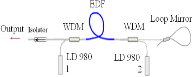
Figure 1. Configuration of the proposed bidirectional double-pass ASE source based EDF.
Download figure:
Standard image High-resolution imageIn this work, the combination of DPF and DPB configurations are used to achieve a C and L band ASE bidirectional source. A length of EDF (20 m) is employed as the active medium where the fiber doping concentration is 1/9 × 1025 ions m−3 and its mode field diameter (MFD) is near 6.5 μm at 1550 nm with an numerical aperture of 0.2. The 3 dB optical coupler is placed at the end of the amplifier to act as a fiber loop mirror. An optical isolator is also employed in our case to block the spurious back reflection and to ensure unidirectional operation of the output. Two 980/1550 nm WDMs are inserted to combine the pump and signal wavelengths as well.
In order to compare the four different configurations, the output spectrum of all arrays was compared and recorded as below.
2.1. SPF
The first configuration is the SPF that is shown in figure 2. Variations of output spectrum against pump power are very fast and lie in the L band region. Another interesting result is the shifting of the output spectrum toward a shorter wavelength by increasing the pump power. The flat bandwidth of this source under 400 mW pump power is also demonstrated at around 40 nm in the L band area.

Figure 2. Schematic output spectrum of SPF as a function of wavelength for various pump powers.
Download figure:
Standard image High-resolution image2.2. SPB
The second configuration is SPB, with its schematic diagram inserted in the inset of figure 3. In order to preventing lasing, the free end of the fiber with an 8° angle is cleaved. This source emits light in the C band region. In comparison, figure 3 shows variations of the spectrum against pump power that are much lower than in the SPF case. According to this figure, a local peak around 1560 nm grows by increasing the pump power as well.

Figure 3. Output spectrum of SPB for various pump powers.
Download figure:
Standard image High-resolution image2.3. SPF+SPB
Another design is the SPF+SPB configuration that is shown in figure 4.
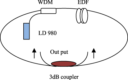
Figure 4. Schematic diagram of SPF+SPB.
Download figure:
Standard image High-resolution imageAs shown in the figure, a 3 dB coupler is used to combine the spectrum of forward and backward photons. Figure 5 compares the spectrum of SPF, SPB and SPF+SPB. Although the total figure is generally similar to SPB's spectrum, variations of the spectrum in 1560–1580 nm are considerable. For this reason the SPB's power is higher than the SPF's, so by the attenuation of the 3 dB coupler the effect of the SPF's spectrum on the SPF+SPB spectrum would be less than the SPB's spectrum due to the lower power of SPF. As forward photons become considerable around 1570 nm, distinctions between SPB and SPF+SPB emerge.
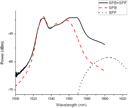
Figure 5. Output spectrum of SPB, SPF and SPF+SPB for the same pump power.
Download figure:
Standard image High-resolution image2.4. DPF
The third basic arrangement is introduced by DPF which includes a broadband reflector (loop mirror) as shown in figure 6.
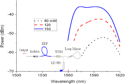
Figure 6. Schematic diagram and output spectrum of DPF for various pump powers.
Download figure:
Standard image High-resolution imageAs demonstrated in the figure, the ASE source at the L band region can be proposed by a simple setup rather than the design of Wang et al [7]. In this work, the flattened area is included in the 1570–1605 nm region (L band).
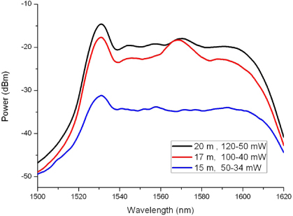
At an input pump power of 150 mW, the measured ASE power of the bidirectional double-pass source varies for different lengths of gain medium within a wide wavelength region from 1560–1620 nm in figure 7. As we show in this figure, the employed higher length (20 m) source is much flatter and less sensitive to power level when compared to other lengths of EDF. Although the total power is less than for the two other shorter lengths, the fluctuation of the power level is less than 3 dB without employing the flattening filters.

Figure 7. The ASE spectra at various lengths of EDF and 150 mW fixed pump power.
Download figure:
Standard image High-resolution imageInstead of a loop mirror, a Faraday rotator mirror (FRM) with 17 nm bandwidth and 1550 nm center wavelength is also examined in this report. Figure 8 compares the spectra of the DPF source for 150 mW pump power by employing the loop mirror and FRM. Because of some limitations, the bandwidth and output power level of FRM were lower than the loop mirror. So, the loop mirror is preferred as a reflector for broadband SFS.

Figure 8. Comparison of performance loop mirror and FRM as a reflector in the DPF setup.
Download figure:
Standard image High-resolution image2.5. DPB
DPB had been also suggested in figure 9 as offering the higher output power and better mean wavelength stability for the C band ASE source [17]. The power spectrum covers the C band region which can be seen by the fact that when increasing the pump power, the portion of photons in the L band increase.
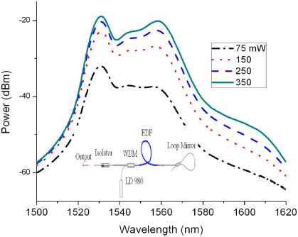
Figure 9. Schematic diagram and output spectrum of DPB versus different pump powers.
Download figure:
Standard image High-resolution imageAs we mentioned before, the output spectrum of SPF and DPF covers the L band and the power spectrum of SPB and DPB covers the C band. Also, the combination of C and L band spectra can be made with specific designs. Also, for increasing the conversion efficiency, it is more efficient to use the DP SFS as demonstrated in recent studies [1].
So, it seems that by seeding the L band photons to a DPB configuration, establishing a C and L band SFS will be possible.
Hence, we proposed a simple array that provides a high power and flat C and L band output. This arrangement is a combination of DPB and DPF setups. The output port of the source is located near the LD1 which for this laser diode makes a DPB state and for LD2 makes a DPF status. The output spectrum of this ASE source is shown in figure 10 as well. Since the output makes a DPB state for LD1, the sensitivity of the spectrum to pump power is low and by adjusting the LD2's power, a flattening of the spectrum will be possible. The output power of this ASE source in 185–50 mW pump power is around 32 mW over a 1525–1605 nm area. The fiber loop mirror is also used in optimum in figure 1 to allow a double propagation of signal and thus increasing the attainable flat gain in both C and L band regions. As a result, this suggested setup is simpler and flatter than other proposed arrays [16, 17].
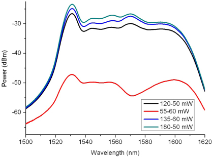
Figure 10. Output spectrum of double-pass bidirectional configuration for various pump powers.
Download figure:
Standard image High-resolution imageFigure 11 also compares the ASE spectra at various lengths and the laser diode pump powers.
Figure 11. The ASE spectra at various pump powers for different length gain mediums.
Download figure:
Standard image High-resolution image
The different choices of pump power are dependent on the cross section emission of the EDF in various cavity lengths, where lasing peaks appear at around a 1560 nm wavelength for higher pump powers, especially in a 15 m long EDF. This is attributed to the system which requires the higher pump power and cavity length to achieve a flatter gain and overcome the lasing generation.
3. Conclusions
This piece of research improved the selection of optimum design for the superfluorescent ASE sources based EDF. DBF and SPS are demonstrated by simple careful source arrays in the L band region as well as the SPB and DPB setups which show flattening output power in the C band region.
The combination of simple setups leads to high flat stability output power to cover the C and L band area. These compact ASE flat sources are also very applicable for broadband sensors, WDM systems etc.