
Abstract
This paper shows the first application of in situ manipulation of discontinuous fibrous structure mid-print, within a 3D printed polymeric composite architecture. Currently, rapid prototyping methods (fused filament fabrication, stereolithography) are gaining increasing popularity within the engineering commnity to build structural components. Unfortunately, the full potential of these components is limited by the mechanical properties of the materials used. The aim of this study is to create and demonstrate a novel method to instantaneously orient micro-scale glass fibres within a selectively cured photocurable resin system, using ultrasonic forces to align the fibres in the desired 3D architecture. To achieve this we have mounted a switchable, focused laser module on the carriage of a three-axis 3D printing stage, above an in-house ultrasonic alignment rig containing a mixture of photocurable resin and discontinuous 14 μm diameter glass fibre reinforcement(50 μm length). In our study, a suitable print speed of 20 mm s−1 was used, which is comparable to conventional additive layer techniques. We show the ability to construct in-plane orthogonally aligned sections printed side by side, where the precise orientation of the configurations is controlled by switching the ultrasonic standing wave profile mid-print. This approach permits the realisation of complex fibrous architectures within a 3D printed landscape. The versatile nature of the ultrasonic manipulation technique also permits a wide range of particle types (diameters, aspect ratios and functions) and architectures (in-plane, and out-plane) to be patterned, leading to the creation of a new generation of fibrous reinforced composites for 3D printing.
Export citation and abstract BibTeX RIS

Content from this work may be used under the terms of the Creative Commons Attribution 3.0 licence. Any further distribution of this work must maintain attribution to the author(s) and the title of the work, journal citation and DOI.
1. Introduction
3D printing techniques have quickly become some of the most useful and prevalent tools in designing and building novel components. These techniques allow for multiple design iterations to be completed in a day, where in the past this may have taken weeks or months employing traditional subtractive manufacturing methodologies. The rapid developments in 3D printing methods such as selective laser sintering and plastic jet printing allow for final components to be manufactured as well as prototypes, with applications ranging from prosthetic limbs and biomedical implants to aeroplane components [1, 2]2 . With the introduction of multimaterial printers, a variety of functional structures have been developed based on these methods [3, 4]. At present, the most common type of 3D printing for component production is fused filament fabrication, wherein a thermoplastic filament is extruded through a heated nozzle and the part is built layer by layer, effectively growing from the print bed. This method is cheap, reliable and allows for a wide variety of materials with different properties to be printed. However, like most 3D printing techniques, the structural properties of the part are relatively poor, and not suitable for producing finished components for high stress purposes [5]3 . Typical printers use thermoplastics, such as polylactic acid or nylon and the inclusion of nano- or micron length scale particulate or fibrous reinforcement within the feedstock material have been shown to improve the mechanical performance of the bulk polymer and have the potential to provide added functionality [6, 7]. In order to use polymeric solutions in high performance applications, the current approach is to use continuous fibres (glass, Kevlar or carbon) to improve the mechanical performance by maximising the fibre-matrix stress transfer. However, continuous fibres inhibit the full potential of complex 3D printed constructs, where a trade-off is required between maximising print quality, print resolution and print speed, with the material performance (which is associated with fibre length, fibre alignment and fibre volume fraction).
Introducing short fibre microscale reinforcements into 3D printed parts is of current interest to improve the structural properties of polymer based 3D printed components [6, 7]. Much of this work is based in fused filament fabrication printing, wherein fibrous reinforcement is included in the thermoplastic feedstock prior to printing. This method produces components with fibres partly aligned to the print path due to the shear flow induced by the print nozzle. Furthermore, since the fibres within the filament align along the direction of extrusion (within the nozzle head), the introduction of any off-axis structure is problematic.
In order to have full control of the distribution and orientation of the microstructure, an alternative to fused filament fabrication printing is required, such that the designer has full 3D placement control of the particles without any imposed manufacturing constraints. Here we show that stereolithography printing coupled with ultrasonic alignment has this potential. To include microstructure in stereolithographic printing, a new processing protocol is required to orient the fibres within the resin tank prior to polymerisation of the host medium. A number of techniques have the potential to manipulate microparticles in suspension, including use of electric, magnetic and acoustic fields, and flow-induced alignment methods [8–10]. The use of electric and magnetic fields typically only allow for the formation of nematic phases [8]. In addition they require the micro- or nano-scale particles to have specific electrical or magnetic properties. The dynamic nature of flow-induced fibre alignment methods is not compatible with stereolithographic 3D printing. Acoustophoresis is a versatile method for distributing and patterning particles within a fluid medium [11]. Here, acoustic radiation forces are generated in a fluid medium (i.e. the host polymer), using counter-propagating plane waves to generate a standing-wave field, leading to steep acoustic pressure gradients. These gradients lead to acoustic radiation forces acting on suspended particles, manipulating them towards either pressure nodes or anti-nodes depending on the relative densities of the fluid and particles [12, 13]. Particles with a higher density than the host fluid medium will be forced towards pressure nodes, while those with lower density will be forced to anti-nodes. This means that, so long as there is acoustic contrast (i.e. differences in density and speed of sound) then any combination of particle and host materials are suitable. In a 1D pressure field neighbouring trap sites are separated by  where λ is the wavelength of the ultrasonic wave in the host fluid [14, 15]. Acoustophoresis has found primarily found application in biological research, particularly in cell sorting/patterning and tissue scaffold engineering [16, 17]. This is due to the requirement for upscaling of the capabilites of optical tweezers to large numbers of particles, as well as reducing the damage caused to biological materials by high intensity lasers [18]. Previous work has proven the efficacy of ultrasonically arranging particles within a resin matrix [19–22]. Mechanical characterisation of such parts demonstrated that structural anisotropy was achieved (8% stiffness and 43% strength anisotropy along the two principal directions) [9]. In this proof-of-concept, we extend this concept to consider the direct integration of acoustophoresis and selective resin curing within a 3D printing process to harness unique complex fibrous geometries not achievable through fused filament fabrication. Here, a method for aligning fibres via the use of acoustic radiation forces is demonstrated, in order to position and align fibres within a photocurable resin system. The resin is subsequently cured using a focused near-UV light source, in a similar way to stereolithographic printing, however the laser is physically moved across the surface of the resin tank instead of being redirected by a rotating mirror, as is typical in commercial systems. The proposed method effectively separates the printing and microstructural formation processes, thus allowing control of discontinuous fibre orientation and ensuring the printing process is unaffected by the inclusion of the new microstructure.
2. Design concept
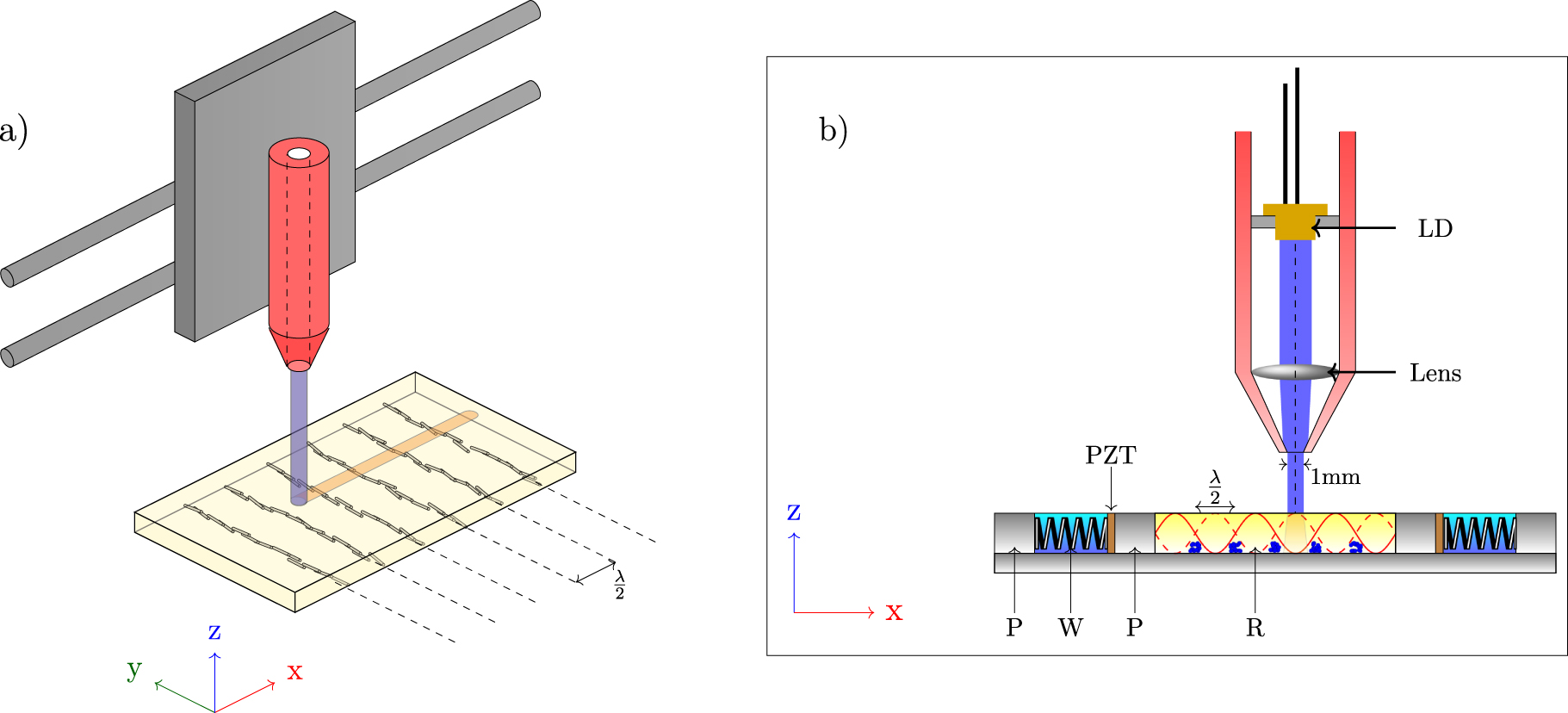
An existing open source 3D printer (Prusa i3) was used to demonstrate the ease of incorporating ultrasonic assembly into an existing fused filament fabrication printer, by replacing the thermoplastic extrusion system. As shown in figure 1, a 405 nm laser diode module was mounted on the print head to cure the resin, with an emitting power of 50 mW. The laser diode was housed in a shroud, and was focused using a single 6 mm diameter lens, with a focal length of 20 mm. The resulting beam was passed through a 1 mm diameter aperture which produces a beam with uniform radial intensity. The laser diode and lens housing were mounted on the x-travel carriage, with the focused beam pointing vertically downwards towards the horizontal print bed (see video 1 in supplementary data found at stacks.iop.org/sms/25/02LT01/mmedia). The ultrasonic alignment stage is shown in figure 1 and was designed to physically separate the piezoceramic ultrasonic transducers (Noliac NCE51) and resin sample, thus enabling the reuse of the transducers should the alignment stage require changing, which is generally the case if the resin has been left unused for more than 1 h as it will have partially cured under ambient light. The design was made to provide a reasonable resin cavity size (35 mm by 35 mm) while driving the transducers below 100Vpp to prevent overheating and damage to the alignment stage. The dimensions of the transducers are 35 mm by 2 mm by 0.975 mm. The two piezoceramic plates were placed in the inner walls of the outer cavities, and held in place with small springs (Lee Spring CIM 040EG01S). These two cavities were then filled with water, which acts as a heatsink during operation of the transducers. The large central cavity was filled with a mixture of a low viscosity photocurable resin (Spot-A LV) and commercially sourced glass microfibres (Lanxess MF7904, length 50 μm, 14 μm). The transducers were then driven in their first through-thickness resonant mode at a frequency f = 2.35 MHz with a driving voltage  This produced an approximately 1D pressure field which caused the glass microfibres to align along acoustic pressure nodal planes in the y–z plane in ∼5 s, with planes equally spaced in x by
  (see video 2 in supplementary data found at stacks.iop.org/sms/25/02LT01/mmedia).
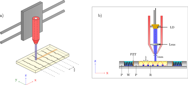
Figure 1. Schematic representation of printer and ultrasonic manipulation rig. (a) Switchable laser module is attached to the print head carriage, and traces out the shape of the printed part. The laser can be deliberately defocused to cure large regions slowly by increasing the height of the laser module. (b) Focused laser beam cures resin within the cavity of the ultrasonic manipulation device. P = PMMA, W = Water, PZT = lead zirconate titanate transducers, R = spot-a low Viscosity photocurable resin. Cross sections of the bundles of fibres lying within traps are shown, and are separated by half a wavelength.
Download figure:
Standard image High-resolution imageInitial tests were performed to determine the resin cure rate under the near-UV light source used, in order to set a suitable print speed. Ideally, the curing rate would solidify the resin through its entire z-thickness (1–2 mm) at a particular point, while not adhering the resin excessively to the rig base thereby allowing removal of the finished part. Driving the near-UV laser diode at 3 V, a print speed of 20 mm s−1 was found to provide the required level of curing in 1 mm depth of resin, allowing for easy separation of the printed part from the glass substrate. It was found to be desirable to use the fastest print speed available (i.e. 20 mm s−1) to cure through the full thickness of the resin, as this prevents warping from residual stresses caused by over-curing on the top surface (i.e. on the laser diode side) of the resin.
3. Results and discussions
Figure 2 shows an example of a printed part with an ultrasonically assembled microstructure, as well as optical microscopy images detailing various regions of the part containing the assembled fibres (see Supplementary Information for full details supplementary data found at stacks.iop.org/sms/25/02LT01/mmedia). Within figure 2, microscope images of sections 2 and 3 include edges of the specimen, with fibres clearly extending to the edge of the parts and maintaining their alignment. Fibre dispersion also appears uniform throughout the part, with an average separation between neighbouring acoustic traps of  . At a frequency of 2.35 MHz and with a speed of sound c = 1400 m s−1 in the resin, the theoretical node spacing,
  is in good agreement with experimental observation.

Figure 2. Optical microscopy images (1)–(4) of various sections of a printed part (centre top) reinforced with ultrasonically aligned glass microfibres, with desired orientation direction shown (centre bottom). In each of the sections, 'stripes' of aligned fibres can be seen with uniform dispersion and an average trap spacing of 300 μm. Sections 2 and 3 show discernible features of the printed part, with fibres extending to the edge of the part and maintaining their alignment.
Download figure:
Standard image High-resolution imageCross-sectional SEM images (shown in figure 3) establish that the bundles of fibres within each acoustic trap in these samples extend approximately 100 μm into the part (z-direction), or  which is comparable to the layer thicknesses used in standard stereolithographic 3D printing. The depth of the fibres was found to be dependent on the fibre volume fraction within the resin, and so can be tailored for the desired layer thickness. The majority of the fibres are also clearly visible 'end-on' throughout the depth of the bundle, showing that a high degree of alignment has been achieved even at relatively large print layer thicknesses.

Figure 3. Cross sectional SEM images of 3D printed component with ultrasonically aligned glass microfibre reinforcement. The cross sectional plane is orthogonal to the alignment axis of the fibres. Back-scattered electron detection was used, with a beam energy of 15 kV. Magnifications for each image are: (a) 100 × (b) 500 ×.
Download figure:
Standard image High-resolution imageFigure 4 demonstrates the ability to orient fibres within the microstructure at any angle with respect to the edge of a printed part. A long rectangular 'strip', 20 mm(length) × 2 mm(width) × 1 mm(thickness), was printed at a variety of angles with respect to the device coordinates. Optical microscopy images of one of the long edges of the part show the fibres extending from this edge at different angles. In all cases the average spacing between fibres bundles is ∼300 μm, and the fibres maintain their alignment to within 50 μm of the edge of the part. The fibre lines are not perfectly parallel which is thought to be due to imperfections in the device, such as slightly misaligned transducers. A consequence of this is that the alignment direction is not perfectly parallel to the print direction.

Figure 4. Demonstration of varying fibre angle within a printed component, with desired microstructure shown in inset. All parts had dimensions 20 mm (l) × 2 mm (w) × 1 mm (t). (a) Fibres aligned along part axis. (b) Fibres aligned at  to part axis. (c) Fibres aligned at
  to part axis. (d) Demonstration of orthogonally aligned reinforcement within the same printed layer.
Download figure:
Standard image High-resolution image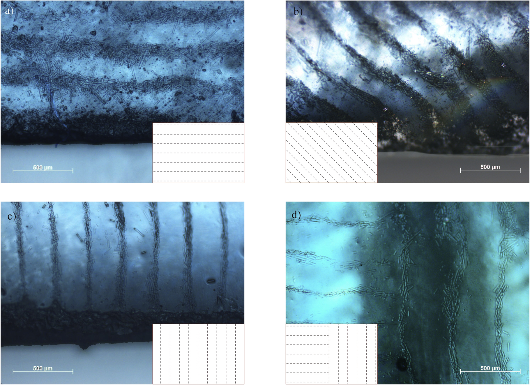
Mid-print realignment was performed by using an identical pair of transducers oriented at  to the original pair to align fibres perpendicular to their original position. The same shape was printed as in figure 2, with the top and bottom cross bars containing fibres aligned using the original pair of transducers. The print is then briefly paused (∼10 s) while the other set of transducers are driven to realign the fibres, after which the remaining central section of the part is printed. Figure 4(d) shows an example of the intersection between the two orthogonally aligned regions from which it can be seen that the two regions of differing alignment were achieved in close proximity (<100 μm). Further work is required to allow thickness control of the printed part, and the ability to print consecutive layers in the z-direction (i.e. on top of each other) with varying fibre orientation layer-by-layer.
4. Conclusions
Clear compositional anisotropy was observed in 3D printed parts using ultrasonic manipulation to distribute glass microfibres within a resin matrix. The anisotropic mechanical properties due to the arrangement of fibres into lines (see figure 2) can be expected to reflect that seen in previous work by Scholz et al, owing particularly to the similarities in alignment technique and reinforcing material used in the present paper [9]. Further experimental testing is required to verify this expectation, and explore the wide range of possible microstructures that this technique is capable of producing. The print speed was determined in order to optimise the printing process for full part curing while allowing removal of the part itself from the resin tank. Further, the alignment process does not significantly interfere with the printing process, and as such print speeds are comparable to those of existing stereolithographic printers. A variety of fibre orientation angles within the same part design were shown to demonstrate the versatility of the process. This work has shown the first example of 3D printing with real time control over the distribution of an internal microstructure, which demonstrates the potential to produce rapid prototypes with complex microstructural arrangements. This orientation control will provide the ability to produce printed parts with tailored anisotropy without compromising toolpaths, thus enabling the production of components for a range of smart materials applications e.g. resin-filled capsules for self healing or piezoelectric particles for energy harvesting.
Acknowledgments
This work was supported by the Engineering and Physical Sciences Research Council through the EPSRC Centre for Doctoral Training in Advanced Composites for Innovation and Science (grant number EP/G036772/1). The authors gratefully acknowledge the support of the UK Engineering Physical Sciences Research Council (EPSRC) for funding Dr Richard S Trask's fellowship and research under EPSRC 'Engineering Fellowships for Growth', (grant number EP/M002489/1).
Footnotes
- 2
Stratasys chosen by airbus to produce 3D printed parts for A350 XWB.
- 3
FDM materials comparison—stratasys.