
Abstract
Photovoltaic materials can turn light energy into electric energy directly, and thus have the advantages of high electrical output voltages and the ability to realize remote or non-contact control. When high-energy ultraviolet light illuminates polarized PbLaZrTi (PLZT) materials, high photovoltages will be generated along the spontaneous polarization direction due to the photovoltaic effect. In this paper, a novel hybrid photovoltaic/piezoelectric actuation mechanism is proposed. PLZT ceramics are used as a photovoltaic generator to drive a piezoelectric actuator. A mathematical model is established to define the time history of the actuation voltage between two electrodes of the piezoelectric actuator, which is experimentally validated by the test results of a piezoelectric actuator with different geometrical parameters under irradiation at different light intensities. Some important characteristics of this novel actuation mechanism are analyzed and it can be concluded that (1) it is experimentally validated that there is no hysteresis between voltage and deformation which exists in a PLZT actuator; (2) the saturated voltage and response speed can be improved by using a multi-patch PLZT generator to drive the piezoelectric actuator; and (3) the initial voltage of the piezoelectric actuator can be acquired by controlling the logical switch between the PLZT and the piezoelectric actuator while the initial voltages increase with the rise of light intensity.
Export citation and abstract BibTeX RIS

Original content from this work may be used under the terms of the Creative Commons Attribution 3.0 licence. Any further distribution of this work must maintain attribution to the author(s) and the title of the work, journal citation and DOI.
1. Introduction
Due to the lightweight trend in space structures, the field of photonic control without accessorial devices and connecting wires has great research value. When ultraviolet light with a wavelength near 365 nm illuminates polarized PbLaZrTi (PLZT) materials, an electrical field can be generated along the spontaneous polarization direction due to the photovoltaic effect [1–3]. Based on the photovoltaic effect and the converse piezoelectric effect, PLZT may also exhibit a photostrictive effect [4–6]. Because of its advantages of non-contact optical control and lower susceptibility to electric/magnetic disturbances, PLZT wafers were used as distributed actuators in the study of photonic vibration control of flexible shells [7–12]. However, there are some demerits of PLZT in photostrictive actuation, such as one-way actuation, the hysteresis phenomenon between the photovoltage and the photodeformation, slow response of the photodeformation and the serious residual voltage and strain after turning off the light [13–15]. In order to remedy these defects of PLZT as an actuator, a hybrid photovoltaic/piezoelectric actuation mechanism was proposed and studied, in which the light-driven photovoltaic generator-induced voltage was used to drive the piezoelectric actuator [16, 17]. It was proven by these studies that the novel actuation mechanism possesses a great potential application in the vibration control and shape control of shell structures and other micro actuation fields, while only a rough mathematical model was established, in which the coupling mechanisms of multi-physics fields and the equivalent resistance of piezoelectric actuator were not taken into consideration. So the precise mathematical model and the characteristics of this novel actuation mechanism need to be studied in depth. In this study, based on theoretical analysis and experimental validation, the constitutive equations defining the time history of the actuation voltage of the piezoelectric actuator are presented. It is experimentally validated that there is no hysteresis between the actuation voltage and the strain of the piezoelectric actuator when using the hybrid actuation mechanism. The feasibility of driving the piezoelectric actuator with multi-patches of the PLZT generator to improve the response speed is experimentally validated. In order to apply this actuation mechanism to the vibration control of the shell, a logical switch between the PLZT generator and the piezoelectric actuator is designed to acquire the initial voltage of the piezoelectric actuator.
2. The mathematical model and experimental validation of the novel hybrid actuation mechanism
In this section, the mathematical model of the hybrid actuation mechanism is established based on its equivalent electrical model. The reliability of the mathematical model is validated by measuring the actuation voltage of polyvinylidene fluoride (PVDF) actuators with different geometrical parameters under the irradiation of different light intensities.
2.1. Mathematical model for the hybrid actuation mechanism
If two electrodes of the PLZT and the piezoelectric actuator are connected by wires, when the PLZT is illuminated by high-energy ultraviolet light with a wavelength near 365 nm, high voltages will be generated between the two electrodes. The piezoelectric actuator can accordingly induce actuation strain based on the converse piezoelectric effect.
2.1.1. Mathematical model of PLZT-inducing voltages with coupling multi-physics fields
When high-energy ultraviolet light illuminates PLZT, as a result of the anomalous photovoltaic, pyroelectric, photothermal and piezoelectric effects, high voltage is generated between the two electrodes of PLZT. The coupling mechanisms of the multi-physics fields are shown in figure 1.
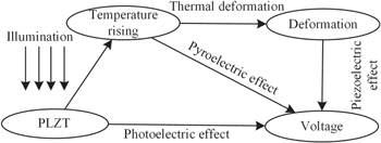
Figure 1. The coupling mechanisms of multi-physics fields.
Download figure:
Standard image High-resolution imageThe generation of photovoltage is a dynamic response to light illumination. The equivalent electrical model of the photovoltaic effect is a parallel circuit of the current source, resistance Rp and the capacitance Cp [18]. Thus, the voltages generated by photovoltaic effect can be approximately written as

where Rp is resistance; ip is photocurrent; Vs is saturated photovoltage, and τ is illumination time constant. The resistance and photocurrent can be respectively written as [18]


where Br, Bi, ar and ai are constants which can be determined by experiments, and I is light intensity.
In the meantime, the light energy also heats up the actuator, and accordingly the body temperature of the PLZT rises. According to the thermal energy balance principle, the additional voltage generated owing to the pyroelectric effect can be deduced as [14]
where A is the illumination area of PLZT and  is the maximal temperature variation,

where GT is the thermal conductance to ambient and  is the thermal time constant,

where CT is the thermal capacitance of PLZT and P is the pyroelectric coefficient of PLZT, and

where Ps is the intensity of spontaneous polarization. When the temperature of PLZT rises, part of the thermal deformation caused by the thermal expansion effect can generate a voltage in opposition to the photovoltage and the pyroelectric voltage. The voltage caused by the thermal deformation and the positive piezoelectric effect can be written as

where  is the conversion coefficient;
  is the thermal stress coefficient of PLZT; d3i is the piezoelectric constant of PLZT, i is the direction of the positive strain in the coordinates system of PLZT, i = 1, 2, 3; and hp and Yp are the thickness and elastic modulus of PLZT respectively. Thus, the total voltages generated by PLZT can be written as
2.1.2. Mathematical model of the actuation voltage of the piezoelectric actuator
According to the above deduction, when two electrodes of the PLZT are connected to two electrodes of the piezoelectric actuator, the equivalent electrical model can be represented as shown in figure 2.

Figure 2. The equivalent electrical model of the photovoltaic/piezoelectric actuation mechanism.
Download figure:
Standard image High-resolution imageAccordingly, the actuation voltage between the two electrodes of the piezoelectric actuator can be written as

where


Where Ca and Ra are the capacitance and resistance of the PVDF actuator respectively,  and
and  are the equivalent thermal capacitance and thermal resistance respectively and according to equation (9):


2.2. Experimental validation for constitutive equations
In this section, experiments are conducted to validate the constitutive equations of this actuation mechanism. PLZT(3/52/48) ceramic with 3 at% La, a Zr/Ti ratio of 52/48 and WO3 as the dopant is selected for this study. The geometric parameter of PLZT is LP × bP × hP = 10 mm × 5 mm × 2 mm and it is polarized along 5 mm. The relative permittivity of the PLZT is 1860. According to our previous experimental work, the photocurrent ip and resistance Rp can be written as: ip = 2.01 × 10⁻¹¹ × I1.01 and Rp = 5.44 × 10¹¹ × I − 0.96. Two PVDF test pieces with different geometric parameters are used: P2 (45 mm × 13 mm × 0.1 mm) and P3 (55 mm × 13 mm × 0.1 mm). When the illumination intensity is 6 kW m−2, the voltage between two electrodes of the PVDF actuator is measured by a high impedance voltmeter. According to the experimental and fitting curves of the voltages, as shown in figure 3, the saturated photovoltages and time constants of PVDF actuators can be acquired as listed in table 1.

Figure 3. Experimental and fitting curves of actuation voltage of PVDF actuator(I = 6 kW m−2).
Download figure:
Standard image High-resolution imageTable 1. Parameters of P2 and P3 by fitting curves when light intensity I = 6 kW m−2.
| P2 | P3 | ||||||
|---|---|---|---|---|---|---|---|
| I (kW m−2) | Vas(V) | τa (s) | R-square | Vas(V) | τa (s) | R-square | |
| 6 | 887.3 | 34.83 | 0.997 | 741.8 | 35.39 | 0.9985 | |
Then the equivalent resistance of P2 and P3 can be calculated as Ra1 = 6.35 × 10¹⁰ Ω, Ra2 = 11.67 × 10¹⁰ Ω respectively. The relative permittivity of PVDF is 9.5, so the capacitance of P2 and P3 are Ca1 = 4.92 × 10⁻¹⁰ F and Ca2 = 6.02 × 10⁻¹⁰ F respectively. Thus, the saturated voltages and time constants of P2 and P3 under the illumination of different light intensity can be calculated as listed in table 2.
Table 2. Theoretical parameters of P2 and P3 under irradiation at different light intensities.
| P2 | P3 | |||
|---|---|---|---|---|
| I (kW m−2) | Vas(V) | τa (s) | Vas(V) | τa (s) |
| 5 | 819.87 | 38.75 | 726.38 | 41.45 |
| 4 | 725.11 | 43.81 | 639.02 | 46.22 |
| 3 | 608.63 | 50.46 | 527.56 | 52.36 |
| 2 | 460.50 | 59.64 | 389.13 | 60.33 |
The comparative curves between theoretical and experimental actuation voltages of P2 and P3 under illumination at different light intensities are shown in figures 4 and 5 respectively. The theoretical and experimental curves do match very favorably, so the mathematical model established can be validated.
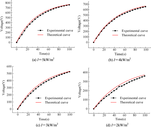
Figure 4. Theoretical and experimental curves of actuation voltages of P2.
Download figure:
Standard image High-resolution image3. Analysis of the hysteresis between voltage and deformation
Since the hysteresis between voltage and deformation can be observed in PLZT ceramics, whether this hysteresis phenomenon exists in the hybrid photovoltaic/piezoelectric actuation mechanism will be analyzed in this section. When PLZT is not connected to the PVDF actuator, the time history of the photovoltage is measured by the high impedance voltmeter, and the deformation of the PLZT ceramics can be directly measured by a laser displacement sensor under irradiation at light intensity I = 6 kW m−2. The experimental results are presented in figure 6. Obviously, the response of strain is much slower than that of photovoltage. This hysteresis phenomenon is considered to be one of the main factors contributing to the slow response of PLZT ceramics when they are used as actuators.
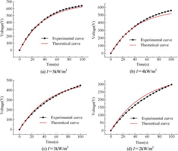
Figure 5. Theoretical and experimental curves of actuation voltages of P3.
Download figure:
Standard image High-resolution image
Figure 6. Time history of photovoltage and strain of PLZT ceramics when light intensity I = 6 kW m−2.
Download figure:
Standard image High-resolution imageIn order to measure the actuation voltage and the strain of the piezoelectric actuator when using the photovoltaic/piezoelectric actuation mechanism, the testing platform is set up as shown in figure 7. The two electrodes of PLZT are connected to the PVDF actuator. The PVDF actuator is laminated on the fixed end of a flexible cantilever beam. When the PLZT generator is illuminated by a LED UV light source, the deflection at the free end of this cantilever beam is measured by a non-contact laser displacement sensor of 0.1 μm resolution. The beam is made of Plexiglas. The geometric and material parameters of the beam and the PVDF actuator are listed in table A1. The time history of the voltages and deflections of the free end of the cantilever beam when using P2 and P3 are presented in figures 8(a) and (b) respectively when the light intensity is 6 kW m−2.
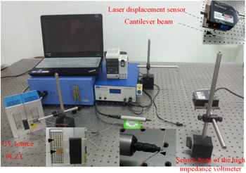
Figure 7. Testing platform for measuring the actuation voltage and strain of the piezoelectric actuator.
Download figure:
Standard image High-resolution image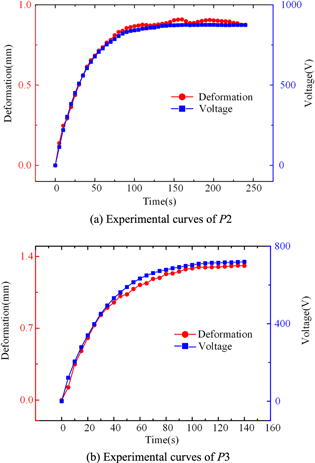
Figure 8. Time history of the actuation voltage and strain of P2 and P3.
Download figure:
Standard image High-resolution imageThe experimental results show that there is no hysteresis phenomenon when the hybrid actuation mechanism is used.
4. Driving piezoelectric actuator with multi-patches of PLZT generator
According to the experimental results, although there is no hysteresis phenomenon when the hybrid photovoltaic/piezoelectric actuation mechanism is used, the response speed of the actuation strain of the PVDF actuator is relatively slow. Driving the piezoelectric actuator with multi-patches of the PLZT generator to improve the response speed will be proposed in this section.
As shown in figure 9, two PLZT generators are connected to the PVDF actuator and both are illuminated by UV lights. When the PVDF actuator (147 mm × 12 mm × 0.1 mm) is connected to one and two PLZT generators, the voltage between its two electrodes and the deflections of the free end of the cantilever beam (350 mm × 12 mm × 1 mm) are measured respectively and compared. The mass density and Young's modulus of the beam are 1.02 × 10³ kg m−3 and 8.05 × 10⁹ N m−2 respectively. When light intensity I = 5 kW m−2, I = 4 kW m−2, I = 3 kW m−2 and I = 2 kW m−2, the experimental results are shown in figure 10.

Figure 9. Diagram of PVDF actuator driven by two PLZT generators.
Download figure:
Standard image High-resolution image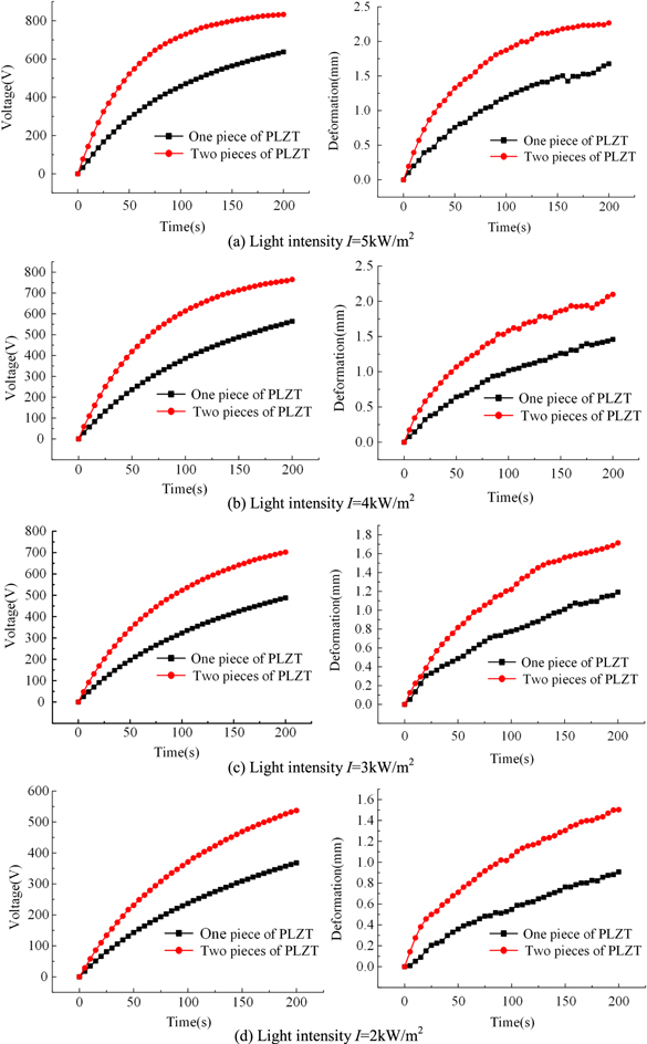
Figure 10. Time history of voltages and deflections of the free end of the cantilever beam.
Download figure:
Standard image High-resolution imageThe saturated voltages and time constants of different light intensities are acquired by fitting the experimental curves using MATLAB software, as listed in table 3.
Table 3. Fitting results of saturated voltages and time constants.
| Single PLZT | Two patches PLZT | |||||
|---|---|---|---|---|---|---|
| I(kw m–2) | Vas(V) | τa (s) | R-square | Vas(V) | τa (s) | R-square |
| 5 | 727.7 | 99.68 | 0.9996 | 850.8 | 53.06 | 0.9998 |
| 4 | 690.8 | 121.5 | 0.9997 | 804.8 | 68.68 | 0.9999 |
| 3 | 624.5 | 135.1 | 0.9995 | 770.3 | 86.22 | 0.9994 |
| 2 | 492.1 | 149.9 | 0.9992 | 642.8 | 114.2 | 0.9993 |
The experimental results show that both the saturated voltage and response speed can be improved by using a multi-patch PLZT generator to drive the piezoelectric actuator, and the response speed will be faster when the light intensity is higher.
5. Method to acquire and improve the initial voltage
Although the response speed can be improved by using a multi-patch PLZT generator, the hybrid photovoltaic/piezoelectric actuation mechanism cannot be applied to high frequency vibration control. Because the initial voltage of the PVDF actuator is zero and the response speed of this actuation mechanism is relatively slow, the piezoelectric actuator can only provide a small amount of control force to the structure when the frequency is high. One of the solutions to this problem would be to acquire and improve the initial voltage of the piezoelectric actuator.
If the PLZT generator is connected to the piezoelectric actuator after it has been illuminated by UV light for a period of time, the initial voltage of the actuator can be acquired. A logical switch connecting the PLZT generator and the piezoelectric actuator is designed to realize ON/OFF control between the PLZT generator and the piezoelectric actuator. It consists of KAQY216 light relays and CD4052 analog switches. The control principle of this logical switch is shown in figure 11. The CT10 analog switches CD4052 are controlled by a signal generator. The IN+ and IN− of port Q3 of KAQY216 are connected to the positive and the negative electrodes of the PLZT respectively. The 41 and 42 of port O1 of KAQY216 are connected to the positive and negative electrodes of the PVDF actuator respectively. When the control signal is on, the KAQY216 light relays break over, thus the two electrodes of the PLZT generator are connected to the piezoelectric actuator respectively. Conversely, when the control signal is off, the KAQY216 light relays cut off, thus the connection between the two electrodes of the PLZT generator and the piezoelectric actuator is cut off.

Figure 11. Schematic diagram of the PLZT-PVDF ON/OFF control.
Download figure:
Standard image High-resolution imageWhen the control signal is on after the UV light is opened, the initial voltage between the two electrodes of the PVDF actuator can be acquired. When light intensity I = 5 kW m−2, I = 4 kW m−2, I = 3 kW m−2 and I = 2 kW m−2, the control signal is on after the photovoltages of the PLZT are approximate to its saturated voltage. The experimental curves of the voltage of the PVDF actuator (147 mm × 12 mm × 0.1 mm) are shown in figure 12.
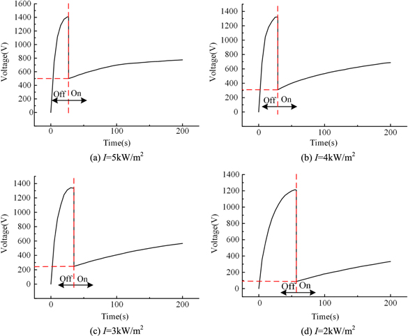
Figure 12. Experimental curves of the voltage of the PLZT generator.
Download figure:
Standard image High-resolution imageWhen the control signal is on, and the voltage of the PLZT generator is equal to that of the PVDF actuator, the initial voltage of the PVDF actuator can be acquired. By comparing the curves of different light intensity, it can also be shown that the initial voltage can be improved by using higher light intensity.
When the logical switch is used, the PVDF actuator-induced actuation strain can be written as

where d3i and ha are the piezoelectric constant and thickness of the actuator respectively;  is the initial voltage of the PVDF actuator.
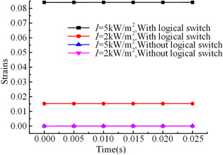
When this actuation mechanism is used for vibration control of the shell structures, the actuator will induce positive control forces to the structure during one half of a period, and induce negative control forces during the other half of a period, and thus the cycle will repeat. The higher the frequency is, the shorter time the actuator-induced control forces needs, and accordingly the actuator can induce less control force to the shell when its initial voltage is zero. When the frequencies are 1 Hz and 20 Hz, the actuator-induced actuation strain with and without logical switch during half a period are compared, as shown in figures 13 and 14 respectively.

Figure 13. The actuator-induced actuation strain during half a period when frequency f = 1 Hz.
Download figure:
Standard image High-resolution imageIt is shown that the actuation strain can be improved to a large degree when using the logical switch and the actuation strain can be increased to a greater degree with higher light intensity. Thus, this novel actuation mechanism can be applied to high frequency control.
Figure 14. The actuator-induced actuation strain during half a period when frequency f = 20 Hz.
Download figure:
Standard image High-resolution image
6. Conclusions
In this study, a novel hybrid photovoltaic/piezoelectric actuation mechanism is proposed and evaluated. The constitutive model of this new actuation mechanism is established and experimentally verified. Some characteristics of this novel hybrid actuation mechanism are experimentally analyzed. The analytical and experimental results obtained indicate that
- (1)The constitutive equations derived by the equal electrical model of this actuation mechanism can approximately define the dynamic response of actuation voltage of the piezoelectric actuator to the illumination time, which is still reliable when the geometrical parameters of the piezoelectric actuator and the light intensity are changed.
- (2)There is no hysteresis phenomenon between the actuation voltages and the strains when using the hybrid photovoltaic/piezoelectric actuation mechanism.
- (3)Both the saturated voltage and response speed can be improved by using a multi-patch PLZT generator to drive the piezoelectric actuator.
- (4)The initial voltage of the piezoelectric actuator can be acquired by using a logical switch between the PLZT and the piezoelectric actuator, and it can be improved by using higher light intensity. Thus, this novel actuation mechanism can be applied to high frequency control.
Acknowledgments
This research is supported in part by two grants from the Chinese Natural Science Foundation (No.51105095, 51575125) and the China Postdoctoral Science Foundation (2014M561358).
Appendix
Table A1. Material properties of the beam and PVDF actuator.
| Property | P2 | P3 | beam |
|---|---|---|---|
| Length | 0.045 m | 0.055 m | 0.14 m |
| Width | 0.013 m | 0.013 m | 0.013 m |
| Thickness | 1 × 10⁻⁴ m | 1 × 10⁻⁴ m | 4 × 10⁻⁴ m |
| Piezoelectric strain constant | 21 × 10−12 C N−1 | 21 × 10−12 C N−1 | — |
| Relative dielectric constant | 9.5 | 9.5 | — |
| Mass density | — | 1.33 × 10³ kg m−3 | |
| Young's modulus | 4.7 × 10⁸ N m−2 | 1.6 × 10⁹ N m−2 |