

Abstract
Multilayer dielectric elastomer actuators (DEA) perform worst off than single-layer DEAs due to higher susceptibility to electro-thermal breakdown. This paper presents a hot-spot model to predict the electro-thermal breakdown field of DEAs and its dependence on thermal insulation. To inhibit the electrothermal breakdown, silicone gel coating was applied as barrier coating to multilayer acrylic DEA. The gel coating helps suppress the electro-thermally induced puncturing of DEA membrane at the hot spot. As a result, the gel-coated DEAs, in either a single layer or a multilayer stack, can produce 30% more isometric stress change as compared to those none-coated. These gel-coated acrylic DEAs show great potential to make stronger artificial muscles.
Export citation and abstract BibTeX RIS
1. Introduction
Dielectric elastomer actuators (DEAs) in a pure-shear configuration can act like muscles to do work [1, 2]. High-voltage activation of them induces either a linear free stroke under an axial pre-load (in isotonic test) or an axial stress change given a constant axial pre-stretch (in isometric test) [2–5]. Stretching helps greatly increase their dielectric strength, in particular for acrylic elastomeric ones whose breakdown field increases from 18 to 218 MV m–1 [2, 3]. Moreover, anisotropic stretching (larger lateral stretching than the axial one) enhances the axial actuation.
Being a soft capacitor, DEAs are susceptible to various breakdown mechanisms [6]. At a low or no pre-stretch, soft dielectric elastomer is prone to partial discharge of embedded air void and electro-mechanical instabilities [7–9]. At a large pre-stretch, the ultimate breakdown of DEAs is often due to electronic avalanche [6, 8, 10] and thermal breakdown [6, 11, 12]. The electrothermally induced puncture (pin-hole formation) through the dielectric membrane ends up with a permanent short circuit [11, 12], and even a membrane rupture [10, 13]. For example, a laterally clamped acrylic DEA of high pre-stretch was reported to survive electro-mechanical instability [10, 14], but eventually succumbed to the electro-thermal breakdown.
Multilayer stacking [15–19] of these DEAs are necessary for force accumulation to make stronger artificial muscles. Yet, multilayer DEAs perform inferiorly as compared to a single-layer DEA [15]. To operate safely, the multilayer DEAs are often activated at a moderate field and thus produce less actuation than single-layer DEAs do. The reasons causing premature breakdown of multilayer DEAs were not clear. Wrinkling could be a lesser issue to multilayer DEAs because the interfaces, sandwiched by two adjacent dielectric elastomer layers, tend less to buckle. The air voids trapped at the interface can also be removed by degassing in vacuum. However, it is noted that local interfacial defects of multilayer DEAs (with self-clearable metallic electrodes) are harder to be cleared completely [20, 21]. Dielectric oil coatings [17] help improve the fault tolerance of multi-layer DEAs (with carbon-base compliant electrodes) despite oil leakage issues [12, 13, 17, 22]. This led us to speculate that the culprit to subpar performance of multilayer DEAs could be thermal insulation.
Recently, we have reported [23] the use of silicone-gel coating (Dow Corning 3-4170) to inhibit the electro-thermal breakdown of single-layer acrylic DEAs (with carbon grease electrodes). The gel-coated acrylic DEAs can tolerate higher electric field before succumbing to the leak-induced puncturing of dielectric elastomer at the hot spot. The report found that the gel-encapsulated acrylic elastomer can withstand a higher degradation temperature of up to 300 °C, as compared to 218 °C of unprotected acrylic elastomer. The beneficial effect of silicone gel coating is expected to apply to other designs of acrylic DEA, such as a pure-shear DEA. Yet, it is not clear whether thermal insulation of multilayer DEA would have adverse impact on the actuator performance, to overwhelm the protection by silicone gel coating.
A hot spot is observed during the DEA's electrothermal breakdown. Here, we develop a simple electro-thermal model to estimate the critical electric field that resistively heat the hot spot to reach the degradation temperature of dielectric elastomer, causing the dielectric puncture. This model will be useful to explain the adverse effect of multi-layer thermal insulation and if gel coating helps. In addition, we shall experimentally demonstrate the improved voltage-induced actuation (both isotonic strain and isometric stress change) of the gel-coated multilayer DEAs.
2. Hot-spot model for electrothermal breakdown
Here, we develop an electro-thermal model (see figure 1) to predict the temperature rise at the breakdown spot on a DEA. The breakdown spot of DEA is subjected to high current leakage and resistive heating and thus develops into a hot spot. Meanwhile, the other healthy parts of DEA remain electrically insulating near room temperature. This model consists of a hot pin and a heat affected zone (HAZ) of annular shape. The hot pin (which corresponds to the hot spot) turns conductive at an elevated temperature before being burnt into a pin hole [24]. The HAZ conducts radially the heat from the hot spot to the surrounding heat sink.
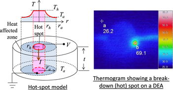
Figure 1. A hot-spot model to predict the critical electric field (Vb/t) that resitively heat the hot spot to temperature Th. The cooling is achieved by heat conduction through the elastomer annulus whose outer boundary is fixed at the ambient temperature Ta.
Download figure:
Standard image High-resolution imageFigure 1 shows that the hot pin has a spot radius of rh and a uniform temperature Th through the dielectric membrane of a uniform thickness t. The annular HAZ of dielectric elastomer membrane has an outer boundary of radius ra fixed at the ambient temperature Ta. At voltage V, current I leaks through the hot pin to generate heat. The resistance of the hot pin can be derived to be  using the Klein's empirical model [6, 25] for electrical resistivity:
  (where
  is the Klein's resistivity at 0 K and a is a material constant). The hot spot is cooled by radial heat conduction [26] across the elastomeric annulus of thermal conductivity k.
The power balance equation for this hot-spot model is

Re-expression yields the electrothermal breakdown field Eb which causes resistive heating of the hot spot to the elastomer's degradation temperature Th = Td:

where Vb is the breakdown voltage.
Acrylic dielectric elastomer (VHB 4905) was reported [23] with a 2%-weight degradation temperature of 218 °C and Klein's electrical resistivity of  = 1.822
 at 0 K, and
  K–1. Electrical breakdown of such a single-layer acrylic DEA (in a circular shape) at room temperature (25 °C) was reported with a hot spot size of 0.15 mm while the outer radius of the HAZ is 0.45 mm. Substituting these parameters in to equation (2) leads to the estimate of electrothermal breakdown field of Eb = 345.6 MV m–1, which is closed to the experimental measured one (without gel coating) [23].
A small HAZ of a 0.45 mm radius was observed surrounding a hot spot on a single-layer DEA [23]. A larger HAZ is expected from multilayer DEAs, especially on their middle layers which are subjected to thermal insulation and less cooling. Consider that a larger HAZ of a ro = 1 mm radius on a 'middle' layer of the multilayer DEA. The electrothermal breakdown field of this middle layer is calculated to be 263.0 MV m–1, a 23% reduction as compared to the one of better cooling (at ro = 0.45 mm). This simple calculation shows the adverse impact of thermal insulation on the electrothermal breakdown.
Silicone gel coating is expected to contain the electro-thermal breakdown as it serves well as an oxygen barrier layer and resists flashover [23, 27]. As a result, it could help inhibit thermo-oxidation of acrylic elastomer from worsening the electrothermal breakdown. Though it does not allow heat convection, the silicon gel coating adds extra passive thermal mass to decrease the rate of temperature rise at the DEA's breakdown spot.
In comparison to the permanent damage rendered by electrothermal breakdown, the effect of electro-mechanical instabilities could be less damaging [10]. The membrane collapse or tension loss [9, 10] under the critically high Maxwell stress could be reversed upon removal of the critically high voltage, if the dielectric membrane was not punctured electro-thermally (i.e. burnt through literally).
3. Experimental section
3.1. Material and fabrication
Consider a bi-axially pre-stretched DEA as shown in figure 2(a). Initial dimensions of the non-prestreched dielectric elastomer membrane are L0 long, W0 wide and t0 thick. Subsequently, the membrane is pre-stretched to be L long, W wide, and t thick. The width pre-stretch is kept by the lateral clamps. The longitudinal pre-stretch is maintained by either a constant pre-load (in the isotonic condition) or a fixed boundary (in the isometric condition).

Figure 2. Fabrication steps for silicone-gel coated acrylic DEA (VHB). (a) From prestreching of VHB membrane to the complete assembly of pure-shear dielectric elastomer actuator; (b) preparation steps for graphite-powder compliant electrodes, its scanning electron micrograph and a photograph in angled view (b) preparation steps of silicone gel coating over compliant electrode and a photograph.
Download figure:
Standard image High-resolution imageFigure 2 shows the making of a single layer of the pure-shear DEA. First, the acrylic elastomer membrane (VHB4905) was pre-stretched laterally for 5 times (a lateral stretch ratio:  = 5) and longitudinally for 2 times (an axial stretch ratio:
  = 2) or more. The pre-stretched membrane was held by a rectangular frame (not shown) for easy handling. Second, graphite powders (Timcal Timrex KS6) were brushed and smeared (through a teflon stencil mask not shown) to make a compliant electrode on the pre-stretched elastomer membrane. Dimensions of the compliant electrodes are 70 mm wide (W) and 10 mm long (L). A scanning electron micrograph (in figure 2(b)) shows a very thin coating of graphite powders. The graphite compliant electrode was measured with an average surface resistance close to 600
  .
.
Dielectric silicone gel (Dow Corning 3-4170) is soft and tacky upon heat curing. Prior to the curing, its pre-polymer comes in a liquid form and it can be drawn cast as a wet film on an elastomeric substrate. Details of the process steps for gel coating are as follow. The liquid pre-polymer was dripped over the graphite compliant electrodes, which is not masked by a liner. A wet film is obtained by drawing an applicator over the liquid puddle. Afterwards, degassing (for 30 min) and heating (at 80 °C for 1 h) of the wet film yield a solid coating of cured gel that well seeps into the gaps among conductive graphite powders on the elastomeric substrate. Repeating the same process yields another gel-coated compliant electrode. The first and second electrodes together sandwich the dielectric elastomer membrane to make a DEA. Next, the obtained DEA was laterally clamped using hard acrylic plates. Finally, the completed actuator was cut out and released from the holding membrane and frame. Free edges of the released DEA relax and neck, causing the wrinkles of gel coating near the edges (see figure 2(c)).
It is relatively easy to multiply the number of the gel-coated DEA but the process steps can be tedious. Figure 3 shows the stacking and bonding process to make a multilayer DEA out of multiple DEA layers. First, we prepared separate layers of DEAs with one-sided solid coating of cured gel. Second, each DEA layer was applied with a wet coating of liquid gel pre-polymer, as interlayer adhesive. Stacking of multiple DEAs (together with holding frames) can be done manually step by step. Next, the interlayer adhesives in this stack is heat cured in one go. Each layer of DEA has a pair of aluminum leads. The leads of positive polarity are connected to a common source while the leads of negative polarity are connected to a common ground. Next the multilayer stack was clamped to rigid plates by adhesive bonding. Finally, the multilayer actuator with the clamps was released to be stand-alone from the holding frames.

Figure 3. Making of multilayer DEAs: (left) preparation of individual layers of DEAs with gel coating (right) stacking of multiple layers of DEAs and arrangement for common leads.
Download figure:
Standard image High-resolution imageFor mechanical tensile characterization, we prepared three types of pre-stretched dielectric elastomer samples, namely (1) gel-coated VHB membrane post heating, (2) non-coated VHB membrane with no heating, (3) non-coated VHB membrane post heating. The gel-coated sample is a pre-stretched VHB membrane with double-side coatings of silicone gel, prepared following the process described for actuator making. Dimensions of these samples (coated or non-coated) are 80 mm wide and 10 mm long after biaxially pre-stretched for 5 times ( ) and 2 times (
 ) in the lateral and longitudinal directions respectively. Their thicknesses before the tensile stretch are: 0.5 mm thick for each solid gel coating and initially 50 μm thick for the pre-stretched VHB membrane. The samples were laterally clamped and axially extensible.
3.2. Methods of characterization
Firstly, we study the stiffening effect of gel coating on a pre-stretched dielectric elastomer membrane. Meanwhile, we also study if there is any side effect of heating (at 80 °C for 1 h) on the pre-stretched elastomer membrane itself. During the tensile testing, various samples (with gel coating, post heating or pristine) were stretched at a rate of 3 mm min–1 and the force required to extend the sample was measured using a 500 N load cell. Differences among their hyper-elastic properties at room temperature will reveal the effect of gel coating and post heating.
Secondly, we measure the electromechanical responses of pure-shear DEAs, in terms of isotonic strain, isometric stress, and breakdown fields. During the electromechanical tests (see figure 4), the actuators are subjected to a step-wise voltage ramp until breakdown. These testings are all done at room temperature (around 20 °C). The driving voltage is provided by a high voltage supply (Spellman's CZE 1000R) and is logged using a data logger (NI-cRIO-9075). Monitor of leakage current across provides a simple way to measure of the DEA health, without the need to locating a defective spot from a micrograph or a thermogram. In experiment, the leakage current is measured using a multimeter (Agilent 34410A) while the DEA is subjected to a voltage ramp.
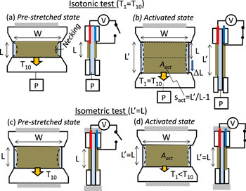
Figure 4. Electro-mechanical test of DEAs in (a)–(b) isotonic condition and in (c)–(d) isometric condition.
Download figure:
Standard image High-resolution imageIn the isotonic test (see figures 4(a) and (b)), the activated DEA elongates axially under a constant pre-load P. The voltage-induced elongation are analyzed from the photographs taken using a digital camera (Canon EOS 550D fitted with Tamron AF 90 mm f/2.8 Di SP A/M 1:1 macro lens). The isotonic strain sact in the longitudinal direction is measured as:

where  is the activated length of actuator, and L is the initial in-activated length (i.e. the pre-stretched length).
Ideally, membrane thickness of the activated DEA can be estimated from the length change given the volume incompressibility and a constant width. However, in practice, the width is not a constant along the length. The pre-stretched DEA membrane could relax and neck at the middle despite the lateral clamps over the ends. As a result, the average membrane thickness needs to be estimated from the area change following:

where t is the pre-stretched membrane thickness initially before the necking formation and Aact is the activated electrode area, which is obtained from the photograph by pixel counting using the ImageJ software. As an approximate, Aact is close to L'W.
Hence, the electric field across the activated membrane of DEA under isotonic test is:

In the isometric test (see figures 4(c) and (d)), the actuator under test was axially stretched for 4 times to emulate the stress change at the maximum voltage-induced isotonic strain. The DEA membrane is kept a constant length ( ) by the fixed ends. Voltage activation of the DEA induces Maxwell stress to reduce the membrane pre-stresses, which was measured using a 15 N load cell of Instron machine.
Ideally, the length and width remains constant for the isometric test. However, due to pre-stretch, the actuator membrane forms a necking at the middle. The voltage activation reduces the membrane necking and thus the electrode slightly expands in area. Hence, calculation of the average membrane thickness and average electric field under the isometric test are similar to the equations (4) and (5) for the isotonic test.
The voltage-induced stress change  is calculated as the tension change over the cross-sectional area of DEAs following

where F0 is the measured pretension at zero voltage and F is the measured activated tension. The passive gel coating does not induces a stress change during the voltage activation even though it increases the pre-tension.
3.3. Thermogram of isometric breakdown
Thermogram can show the temperature distribution of a DEA during a persisting breakdown (with high current leak). An infared camera (Thermo Shot F30, NEC Avio Infrared Technologies Co. Ltd) was used to measure the breakdown thermogram of a DEA sample in a dark box. The DEA samples under the isometric test are activated by a step-wise voltage ramp until the breakdown. Thereafter, the breakdown voltage is held constant so that the DEA breakdown persists for a while for thermal imaging.
4. Results and discussions
First, we characterize the elastic properties of pre-stretched dielectric elastomer membrane and investigate the effect of gel coating and heating on it. The baseline of tensile force requirement is obtained from the extension of a pre-stretched membrane of dielectric elastomer, which is 80 mm wide and 10 mm long (at the initial pre-stretches of 5 times by 2 times). Figure 5 shows that heating at 80 °C for 1 hour does not affect the modulus of the pre-stretched VHB membrane, but it has impact on the ultimate elongation. On the other hand, it is noted that the thick gel coating (2 × 0.5 mm thick initially) adds stiffness to the thin dielectric elastomer membrane (50 μm thick initially). The gel-coated sample requires more force for extension than the non-coated ones. For example, at the stretch ratio of 2, the initial blocked force needed is 0.6–0.65 N for the gel-coated sample, higher than 0.5–0.53 N for the non-coated ones. In the actuation range (with the stretch ratio from 2 to 4), the gel coating sticks well to the elastomer substrate and adds the axial stiffness by 20%–30%. Delamination of the gel coating off the VHB substrate occurs when the stretch ratio exceeds 10.54.
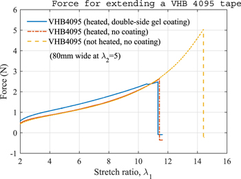
Figure 5. Tensile testing of none-coated and gel-coated samples of pre-stretched VHB membrane (80 wide at a lateral stretch ratio of 5). Silicone-gel coatings (2 × 0.5 mm thick) sandwich the VHB membrane and stiffen it.
Download figure:
Standard image High-resolution imageFigure 6 shows that the voltage-induced elongation in the isotonic test. The voltage-induced axial strain (sact) increases with the applied electric field. It is noted that gel-coated DEAs, either in a single layer or a three-layer stack, can sustain higher breakdown electric field (close to double), as compared to the non-coated ones. However, the gel coated DEAs produce lesser voltage-induced strain given the same electric field, due to the added stiffness of gel coating. Eventually at a higher breakdown field, the gel coated DEAs manage to produce a close to 110% ultimate isotonic strain. This improved dielectric strength of gel-coated DEAs is believed to be attributed to the prevention of localized electro-thermal breakdown as explained [23], and the added thermal mass of passive gel to resist the temperature rise.
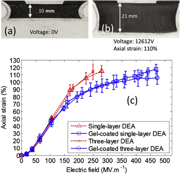
Figure 6. Voltage induced elongation of various DEAs (three samples each) under isotonic tests: (a)–(b) the photographs of a three-layer gel-coated DEA at 0 kV and 12.26 kV respectively; (c) the isotonic strains for various DEAs as a function of applied electric field.
Download figure:
Standard image High-resolution imageIn the isometric test, voltage activation reduces the membrane tension of the pre-stretched DEA. Hence, as shown in figure 7(a), the blocked force needed to keep the DEA membrane taut at a fixed length (20 mm) decreases with a voltage ramp. During each voltage step, the blocked force decreases stepwise and relaxes exponentially over time. Given the same voltage step, the gel-coated DEAs produce lesser voltage-induced force decrement as compared to the none-coated ones due to the added passive stiffness of gel coating. The force reduction continues with the voltage ramp until breakdown. Towards the breakdown, the voltage-activated membrane tension becomes unstable. At the moment of terminal breakdown, the blocked force surges up from the activated low to the high pre-tension.

Figure 7. Voltage-induced change in the blocked force or isometric stress of various DEAs: (a) time history of the total blocked force (for keeping the axial stretch at  ) in response to a step-wise voltage ramp; (b) the voltage-induced isometric stress change as a function of applied electric field.
Download figure:
Standard image High-resolution imageThree-layers DEAs are found to generate more force change than single-layer DEAs. Yet, the dielectric strengths of multilayer DEAs are lower (than those of single-layer ones) due to thermal insulation. The none-coated three-layers DEAs are subjected to isometric breakdown at 4 kV, lower than the 6 kV breakdown voltage of a single-layer one. Fortunately, the gel coating helps make the acrylic DEA thermally more stable, and help the DEA withstand higher electric field before succumbing to electro-thermal breakdown. Figure 7(b) shows that the gel-coated DEAs produces a higher change of isometric stress as compared to the none-coated ones. The maximum voltage-induced isometric stress change in the gel-coated DEAs is 30% higher, thanks to the improved thermal stability and electric breakdown field.
The I–V curves in figure 8 provides a simple monitor of the DEA's health during high-voltage activation. It is noted that the leakage current through a DEA increases with a voltage ramp. Transient current spikes are observed during the voltage ramp due to either the circuit switching or transient arc discharges, which eventually diminish. The ultimate electrothermal breakdown is marked by a current surge of up to the supply current limit and a voltage fall below the pre-set value.

Figure 8. Typical I–V curves of the DEAs under the isometric test with stepwise voltage ramp until breakdown.
Download figure:
Standard image High-resolution imageThe gel-coated DEAs can survive much higher field than the non-coated ones. It is noted that gel coating helps reduce the leakage current, suppress transient current spike, and most importantly prevent the dielectric puncturing. The ultimate failure of the gel-coated DEA, for example the 12 kV or higher breakdown voltage, is a result of the air breakdown with arching between the sample and neighboring ground. As compared to single-layer DEAs, three-layer DEAs are subjected to higher leakage current at the same voltage due to multiples of electrical capacitance and electrode area.
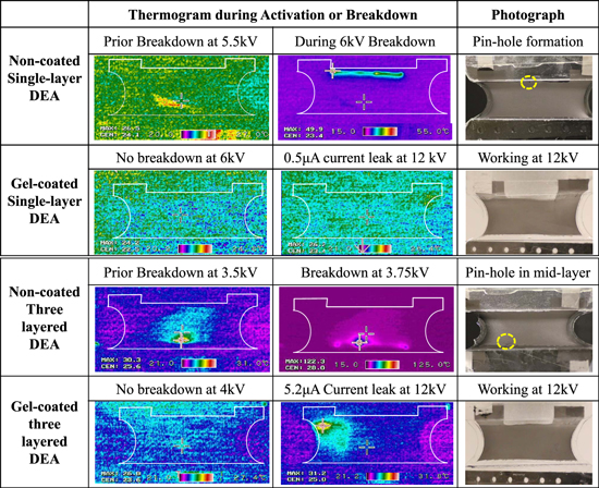
Thermograms in figure 9 show the hot-spot development of various DEAs tested under isometric condition, and the corresponding photograph shows the pin-hole formation. The thermograms shows temperature distribution obtained raw from the camera software without correction for emissivity. A healthy DEA has uniform temperature distribution near the room temperature, despite the presence of some leakage current prior the ultimate breakdown. The breakdown of non-coated DEA is clearly marked with a hot spot and HAZ. In addition, heat path was also shown if there is resistive heating along the graphite electrode. The major hot spot coincides with the location of a pinhole as a result of leak-induced resistive heating. In addition, it is noted that the breakdown of multilayer DEAs is accompanied by a higher hot spot temperature and wider heat spread (a larger HAZ). For the broken 3-layer DEA, the intact cover layers protude slightly due to the pinhole formation in the middle layer. These observations suggests that thermal insulation of multilayer DEAs leads to poorer cooling and thus higher susceptibility to electrothermal breakdown.
Figure 9. Thermograms and corresponding photograph of various DEAs tested under isometric condition. The thermograms show the development of a hot spot and the effects of multilayer and gel coating.
Download figure:
Standard image High-resolution image
5. Conclusions
This paper presented a hot-spot model to predict the electrothermal breakdown field of DEA. Its good agreement with the experimentally measured breakdown strength confirms the ultimate breakdown of acrylic DEAs to be localized electrothermal breakdown. Thermograms of breaking down multi-layer DEAs showed a wider spread of HAZ around the hot spot due to thermal insulation, as compared to a single-layer DEA does. As a solution, dielectric gel coating was applied to protect compliant electrodes of DEA. The protection by gel coating is found effective to reduce the leakage current and to inhibit the electro-thermal breakdown of multi-layer acrylic DEAs. Hence, the silicone-gel-coated acrylic DEAs can sustain higher electric field and produce a higher isometric stress change, as compared to the none-coated ones. This finding is important to make stronger multilayer acrylic DEAs.
Acknowledgments
This research was supported by Singapore Millennium Foundation funded by Temasek Trust. The fourth author Mr M Shrestha is grateful to Singapore Center for 3D Printing (SC3DP) for supporting his PhD scholarship.