

Abstract
This paper presents the model and design of a novel hybrid piezoelectric actuator which provides high active and passive performances for smart structural systems. The actuator is composed of a pair of curved pre-stressed piezoelectric actuators, so-called commercially THUNDER actuators, installed opposite each other using two clamping mechanisms constructed of in-plane fixable hinges, grippers and solid links. A fully mathematical model is developed to describe the active and passive dynamics of the actuator and investigate the effects of its geometrical parameters on the dynamic stiffness, free displacement and blocked force properties. Among the literature that deals with piezoelectric actuators in which THUNDER elements are used as a source of electromechanical power, the proposed study is unique in that it presents a mathematical model that has the ability to predict the actuator characteristics and achieve other phenomena, such as resonances, mode shapes, phase shifts, dips, etc. For model validation, the measurements of the free dynamic response per unit voltage and passive acceleration transmissibility of a particular actuator design are used to check the accuracy of the results predicted by the model. The results reveal that there is a good agreement between the model and experiment. Another experiment is performed to teste the linearity of the actuator system by examining the variation of the output dynamic responses with varying forces and voltages at different frequencies. From the results, it can be concluded that the actuator acts approximately as a linear system at frequencies up to 1000 Hz. A parametric study is achieved here by applying the developed model to analyze the influence of the geometrical parameters of the fixable hinges on the active and passive actuator properties. The model predictions in the frequency range of 0–1000 Hz show that the hinge thickness, radius, and opening angle parameters have great effects on the frequency dynamic responses, passive isolation characteristics and the locations of their peaks and dips. Furthermore, the output actuating force can be improved by increasing the hinge hardness, which is controlled by its dimensions, although increasing the hinge hardness may cause a decrease in the free displacement and passive insulation performance, particularly at low frequencies.
Export citation and abstract BibTeX RIS
1. Introduction
The development of a piezoelectric actuator with high active-passive performance has been a challenging topic in many smart structural applications, and attracted the attention of numerous researchers in the last decades [1–13]. In active-passive vibration isolation presented in [8–10], for example, the applicable actuators should work simultaneously to isolate the mechanical transmission of kinetic energy at mid and high frequencies and generate sufficient forces to control the structural vibrations at low frequencies, which implies that the actuators must be designed to be capable of controlling the system both actively and passively. The electro-mechanical and physical properties, such as dynamic stiffness, blocked force, free displacement, dimensions, weight, and even manufacturing possibilities are the most important points in the design of an ideal actuator. The mechanical stiffness characteristic significantly affects the passive isolation performance, while the blocked force and free displacement properties determine the level of the active control force and output displacement under voltage excitations. Adding extra weight and size to the smart systems is undesirable in many cases, such as in aircraft applications. Therefore, lightweight and easy-to-install actuator devices are also needed.
Nowadays, actuator technology has been intensely involved in all the fields of industrial applications for supplying forces and dynamics. Consequently, a large variety of actuators with different configurations, mechanical and electrical properties, and implementations have been developed and commercially marketed. Generally, the input energy to an actuator is either hydraulic, pneumatic, thermal or electrical, while the output is typically mechanical work. Although hydraulic and pneumatic actuators can apply ultra-high actuating forces and displacements, they cause incredible increase in mass and space to the overall system. In addition, hydraulic actuators as well as pneumatic and thermal actuators are usually limited to low-frequency and low-accuracy systems [13]. Electrodynamic actuators are normally composed of heavy magnetic components and long metallic coils [14, 15]. Thus, inductive heating and significant loss in energy may occur due to the electrical resistance of the electromagnetic coils. However, in the last decades, a new class of actuators using smart materials can provide alternative solutions for achieving high energy efficiency, light-weight, small, and cost saving systems. The piezoelectric actuators, for instance, can generate about 10 times more energy per mass and 100 to 1000 times more work per volume than that of electromagnetic or hydraulic actuators [46]. There are a number of actuators using different types of smart materials in the applications of structural vibration, motion and control systems, including, for example, piezoelectric actuators, piezo-magnetic actuators, shape-memory alloy actuators, magnetostrictive actuators, electroactive polymer actuators, etc. However, the actuators most widely used nowadays are piezoelectric actuators due to the fact that they can produce high levels of forces and fast dynamic responses without significant disadvantages in terms of mass, size or electrical consumption. Thus, a large number of designs of piezoelectric actuators are reviewed frequently in the literature, which can be generally categorized as direct or indirect piezoelectric actuators. A typical direct actuator, such as a PZT (Lead Zirconate Titanate) patch or rod, is widely used to generate mechanical energy or motion without integrating with an external structure [16, 17]. In general, direct actuators are constructed by means of a single layer of piezoelectric material sandwiched by a pair of electrodes. They are principally a mechanical work generator, or motor, since a direct piezoelectric actuator is capable of generating a force and displacement at the boundaries, when it is activated, and therefore doing a mechanical work. However, direct actuators suffer from being not able to satisfy the demands of most industrial applications, which require higher actuating displacement, due to the fact that the free strains of a natural piezoelectric material are extremely small, on the order of 0.1%–0.2% of the material size [18]. In the last two decades, a significant effort has been directed towards the development of mechanisms that can indirectly enlarge the output displacements of direct actuators enough to be applicable in industrial fields. The basis for indirect actuation devices is that a greater displacement can be achieved using an amplification system including one or more direct actuators in order to magnify their dimensional changes. There are various types of indirect actuation devices well attested to in the existing literature. Basically, they can be grouped into three main categories: externally leveraged, frequency leveraged, and internally leveraged actuators [19–21], which can be either applied independently or combined together.
Externally leveraged actuators use external amplification mechanisms (e.g. a lever arm [20–22], a hydraulic mechanism [23–25], or a flextensional mechanism [26–32]) to increase the actuating displacement response. The external mechanisms are usually complex structures that contribute significantly to the overall weight and dimensions. Also, they afford extremely low passive isolation for structural vibration and control system applications due to the high stiffness of the mechanism. Frequency leveraged actuators can generate linear or rotational motions relying on friction and pressure of contacting surfaces between piezoelectric elements and external structures, e.g. inchworm motors [33–35] and ultrasonic actuators [36–38]. Frequency leveraged actuators are able to produce unlimited displacement using a number of actuator elements moving rapidly in one direction but with different phase shifts. However, the overall frequency response is very slow and their applications are usually limited to light and multi-axis positioning systems. Internally leveraged actuators, in contrast to externally leveraged actuators, use internal structure components to generate relatively high actuating displacements instead of external mechanisms [19, 20]. A typical internally leveraged actuator utilizes either a bending mechanism, such as bi-morph bending cantilevers and uni-morph bowing actuators, or parallel expansion/contraction mechanism, such as stack actuators [19].
Stack actuators are generally constructed by means of multiple layers of piezoelectric materials sandwiched by pairs of electrodes and bonded to each other using adhesive materials. A typical stack actuator can be applied independently or integrated with external amplified mechanism as a source of force. The improvement of this type of actuator is usually obtained by stacking a sufficiently large number of piezoelectric layers in opposite polarization directions, which change their dimensions (i.e. expansion or contraction) simultaneously, in order to increase the total strain. The other category of internally leveraged actuation devices uses one or more piezoelectric patches. This type of device can be either constructed as a unimorph actuator by bonding a single piezoelectric layer to a flexible passive layer or as a bimorph actuator by attaching a double layer of piezoelectric patches to each other or to a passive layer between them [19]. When the piezoelectric patches are active, high shear stresses are generated between the bonded layers creating an internal bending moment along the actuator and thereby high deflection. Although unimorph and bimorph actuators are capable of providing ultra-high displacement and better passive isolation with minor size and mass penalties in comparison with externally leveraged actuators, the output actuating force is generally weaker and, in some applications, not sufficient. Thus, new classes of unimorph actuators, known as 'mechanically pre-stressed internally leveraged bending actuators', such as RAINBOW [19, 39], CERAMBOW [19], CRESCENT [19, 40], C-block [19], and THUNDER [19, 41], have recently been introduced in many research and studies to enhance the dynamic response and mechanical load capability [46].
The THUNDER (thin-layer composite-unimorph ferroelectric driver and sensor) actuator was developed by the NASA Langley Research Center (LaRC) in 1994 [19] as a new actuator technology offering high output displacement and improved loading force capabilities. As shown in figure 1, a typical THUNDER actuator is composed of a piezoceramic wafer (e.g., PZT-5H or PZT-5A) bonded under high temperature and pressure to a relatively thick metallic backing sheet (e.g., aluminum, copper, or stainless steel) and an upper thin sheet of metal acting as an electrode using a LaRC-SI adhesive layer [42]. Then, the composite structure is progressively cooled down to ambient temperature. During the cooling process, the adhesive layers solidify at around 270 °C, creating pre-stressed conditions in the bonded layers due to the effect of the thermal expansion coefficients, and thereby an out-of-plane curvature. Thus, the final radius of curvature of the actuator, when inactivated, depends only on the amplitude of the ambient temperature. Since the Curie points of PZT-5H and PZT-5A are around 195 °C and 365 °C, respectively, some loss of polarization may occur in the piezoelectric layer [19–21]. Therefore, a re-poling process must follow the cooling phase by subjecting the actuator to a high DC voltage along its thickness [19]. Thus, both the thermal and re-poling effects must be considered in the modeling of the actuator. Figure 2 illustrates a typical THUNDER actuator after cooling and re-poling processes. Practically, activating the piezoelectric layer generates out-of-plane flexural vibrations in the THUNDER actuator. As the piezoelectric material is activated by positive and negative voltages, in-plane expansions and contractions in direction 1 are produced in the piezoelectric layer causing an in-plane compression/tension stress field on the surface of the backing sheet, and thereby out-of-plane vibrations in the actuator, as shown in figure 3. The thin curved metallic backing layer, which supports the composite layers, provides high bending flexibility to the structure, and thereby increases the mechanical insulation coefficient of the actuator. In addition to its passive performance, the pre-stressed characteristic and curved shape of the actuator improve the active strain and loading force performances relative to conventional unimorph and bimorph actuators.

Figure 1. Shape and configuration of a THUNDER element before and after cooling process.
Download figure:
Standard image High-resolution image
Figure 2. A manufactured THUNDER actuator model TH-8R.
Download figure:
Standard image High-resolution image
Figure 3. Active deformation of a typical THUNDER actuator: (a) cantilever mounting; (b) simply-supported mounting.
Download figure:
Standard image High-resolution imageFor active vibration isolation and active structural acoustic control (ASAC) systems, in which both active and passive controls are required, THUNDER is a perfect actuator to be considered in the design of an actuator device with high active-passive performances. Thus, a number of actuator models using THUNDER elements have been presented in several studies about enhancing the active and passive vibration control. The simulation of a simple four-degrees-of-freedom model with active actuators and experimental investigations for active vibration isolation design of a vehicle seat and passenger using THUNDER elements was addressed by Malowicki and Leo [2]. In the same field of study, Marouzand and Cheng [1] discussed the active-passive effects of THUNDER actuators by predicting and testing the active and passive vibration isolation performance of a single-degree-of-freedom system. However, these studies focused generally on the feasibility of improving the vibration isolation of a system by applying active THUNDER actuators without attempting to enhance the actuator priorities. Similarly to stacked actuators, the active and passive properties of THUNDER actuators can be increased by integrating one or more THUNDER actuators with external amplification mechanisms. Although amplification mechanisms of stacked actuators have been widely presented in numerous studies, only few of them have addressed the amplification mechanical device involved in using for THUNDER actuators. Because of the curved shape and out-of-plane deformation of THUNDER actuators, the design of an appropriate mechanism is not as easy as it seems. In the design of the actuator device, the THUNDER actuator can generally be supported by two methods, as shown in figure 3, using either: (a) a hard clamping mechanism applied to only one tab so that it behaves as a cantilevered beam; or (b) a soft clamping mechanism at both tabs to make the actuator acts similarly as a simply-supported beam. The cantilever mounting method, in fact, needs very simple mechanism since one of the tabs is fixed and the other deforms freely. Also, this method can extremely improve the actuating displacement performance. However, the output forces that can be produced are very weak and, in many cases, insufficient for some applications. In order to achieve a more practical actuator design providing high active loading capability and dynamic response, the second supporting method must be applied.
An active device using a single THUNDER element bonded at its tabs to the free ends of two thin aluminum sheets was developed in [4]. This soft clamping provides a simply-supported boundary condition to the actuator and therefore can increase the passive insulation of energy transmission. Another actuator configuration was presented by Gao and Cheng [5], in which a pair of THUNDER actuators were used. These elements were attached to two thin V-shaped stainless steel sheets to provide very soft clamping support. The experimental tests in this paper showed that integrating two THUNDER elements can generate higher active displacement than one THUNDER does. Although the use of very soft and flexible clamping mechanisms for an actuator increases the active dynamic response, which is desirable in some cases, in many cases, however, it makes the actuator vulnerable and significantly decreases the actuating force. Thus, to increase the output force of the actuator, a new amplification mechanism design was introduced in a number of research works by stacking multi pre-stressed piezoelectric unimorph elements mounted in a parallel way either vertically [43] or horizontally [5, 44] on sliding side mounts. It was demonstrated that the actuating force can be maximized by stacking more piezoelectric elements, but the increase in piezoelectric elements decreases the actuator dynamic response and passive isolation performance. Also, since the ends of the piezoelectric elements are either connected to rotational joints or received in slots, which are located in side mounts sliding on the actuator housing structure, high friction may occur on the sliding and rotating surfaces, particularly at high vibrational frequencies. The use of this design of amplification mechanism is therefore limited to low-frequency applications. Although a number of amplification mechanisms for pre-stressed unimorph bending actuators from different studies have been introduced in this research, no mathematical models have been performed yet to predict and optimize the active and passive actuator properties. These studies simply model the actuator structure as a spring-damper system to analyze its dynamic responses, in with its passive properties, such as stiffness and damping coefficients, and active properties, such as free displacement and blocked force per unit voltage, are obtained experimentally in labs. Thus, this paper presents alternative solutions to these problems by designing a novel piezoelectric actuator has the ability of controlling its output work and also developing analytical and experimental modelling of the actuator to achieve optimal active and passive performances.
In this research, a new amplification device for pre-stressed unimorph bending actuators is proposed. The device uses two THUNDER elements linked to each other by means of a fixable clamping mechanism. Furthermore, a mathematical model is developed for obtaining the electromechanical properties and describing the dynamic responses under mechanical and electrical excitations. The analytical model is validated experimentally and then implemented in the design and optimization of the clamping mechanism. In the rest of the paper, detailed description of the presented actuator device is given in section 2, and analytical dynamic modeling is developed in section 3. Experimental measurements with model validation are carried out in section 4. To achieve the highest level of the active and passive performances, a parametric study is performed to optimize the mechanical device in section 5.
2. Actuator design
The configuration and design of the actuator device is the main task in this study. The actuator model must be capable of working as a passive isolator and active mechanical generator so that it can be applied efficiently in coupled active and passive control systems and many other applications. Generally, the dynamic stiffness, actuating force and displacement capabilities, size, weight, ease of installation and also the possibility of manufacturing are the most considerable factors in the design of a multi-application actuator system. The mechanical stiffness of the actuator has a significant influence on the performance of passive isolation while the blocked force property plays an important role in the evaluation of the level of the active force control. The problem of adding extra weight and complex structure to a system is undesirable, in many cases.
The actuator device is composed of one pair of THUNDER piezoelectric elements, which are mounted opposite each other using two aluminum clamping mechanisms. In this study, a THUNDER model TH-8R (Face International Corporation), shown in figure 2, is considered to generate sufficient active work in the system. The THUNDER actuator can be generally divided into three regions: two tabs on either side of the actuator and a PZT-region. The tabs remain flat since each region consists of only one metallic layer. Thus, they are not subjected to thermal or re-poling strains. Tab-regions are usually used for gripping the actuator. The multi-layer or PZT region is curved because of the mechanical pre-stressing of the piezoceramic and metallic backing layers during the manufacturing process. The material parameters and physical dimensions of the THUNDER element layers are described in table 1. Since the dome height of the THUNDER TH-8R is about 0.151ʺ (3.84 mm) [45], which is very small for some applications, the clamping mechanisms play a role not only in the installation of the piezoelectric elements, but also in increasing the device length to achieve the desirable length. Each clamping mechanism consists of a rigid link in the middle ending with elastically fixable hinges at the corners and then two grippers including very narrow slots at the ends of the mechanism to grasp the tab regions of the piezoelectric elements. The grippers can tighten the elements using screws at the center, as shown in figure 4. This mechanical system allows the piezoelectric elements to vibrate as fully simple-supported curved beams with higher electromechanical responses at the midpoints of the actuators. Rigid and lightweight mounts fastened at the midpoint of each piezoelectric element are used to attachthe actuator device to the systems that need to be controlled. In this case, the mounts transmit mechanical energy from the actuator to the attached systems. The mounts are made of non-conductive material, such as plastic, to avoid any electrical conduction between the actuator electrodes.
Table 1. Geometrical and material properties of the layers used in a THUNDER model TH-8R.
| Material | Thickness mm | Width mm | Density 
|
Young's modulus 
|
Poisson's ratio | Thermal coefficient 
|
Piezoelectric coefficients 
|
Loss factor |
|---|---|---|---|---|---|---|---|---|
| Stainless steel 304 | 0.15 | 13.7 | 8000 | 193 | 0.29 | 17.8 | 0.008 | |
| PZT-5A Wafer | 0.20 | 12.7 | 7750 | 62 | 0.30 | 3.5 | 171 | 0.05 |
| LaRC-SI adhesive | 0.025 | 12.7 | 400 | 5 | 0.40 | 59.0 | 0.35 | |
| Aluminum 3003 | 0.025 | 11.7 | 2730 | 72 | 0.33 | 24.7 | 0.01 |
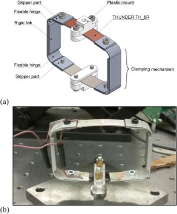
Figure 4. A prototype design (a) and photo (b) of the proposed actuator device.
Download figure:
Standard image High-resolution imageAn individual clamping mechanism can be divided into five parts: a rigid link, two fixable hinges and two grippers, as shown in figure 4. The grippers attach the THUNDER elements to the clamping mechanism while the link ties the two piezo elements and also elongates the device to the desirable length. In case of actuator design, the hinges are the critical parts in the clamping mechanism because the hinge configuration significantly influences the passive and active performances. In general, the hinge mechanism behaves as translational and rotational (in-plane) spring systems at the actuator corners with stiffness parameters depending on the dimensions of the hinges. Thus, radius, thickness and degree of hinge curvature are the influential dimensions which play important roles in the control of the actuator flexibility and the output actuating force and displacement.
3. Theoretical model
3.1. Modeling of the post-manufacturing shape of a THUNDER element
In this section, an analytical model has been derived using classical lamination theory for a piezo-composite laminate in order to predict the room-temperature geometrical dimensions of a THUNDER element after manufacturing processes. To formulate the mode, a number of assumptions are made, including, all components are homogeneous and perfectly bonded to each other, the total thickness of the piezo-composite actuator is small compared to its length and width, and the change in the plane cross-section is negligible. It is assumed also that the deformations in y–z and x–y planes are very small compared to that in x–z plane and can be neglected, and the neutral axis remains fixed. Thus, based on Love and Timoshenko theories [47, 49], the total strain field of a composite curved thin beam in x–z plane can be expressed as

where  are the axial strain and curvature along the neutral axis, resulting from the internal axial force and in-plane bending moment. The total strain can be also defined as the superposition of the thermal, mechanical and electrical strain and the strain resulted after re-poling process [42, 48],

where:
-
 which denotes the mechanical strain, and are the stress and Young's modulus.
 -
which denotes the electrical strain, and are the piezoelectric coefficients, applied voltage, and patch thickness.
-
which denotes the re-poling strain, and are the Poisson ratio and saturation electrostriction due to dipole alignment [42].
-
which denotes the thermal stain, and are the thermal expansion coefficient and temperature difference.


Substituting equation (2) into equation (1), a new formula describing the axial strain and curvature can be written as:

Also, the above equation can be rewritten in term of stress as
Now, integrating all the terms over the composite cross section area gives
where the terms:
-
describes the mechanical load at the neutral axis due to external forces,
-
describes the electrical load at the neutral axis due to output voltage,
-
describes the re-poling excitation, and
-
describes the thermal excitation due to differential thermal expansion.


However, to determine the final configuration of the actuator after manufacturing process, only the thermal and re-poling effects are considered, while the mechanical and electrical excitation terms are absent. Also, because of the symmetry above and below the neutral axis, the term  is zero. Thus, equation (5) can be reduced as,
Therefore, the solution of the axial stain  can be calculated from equation (6), as
Similar to the axial stain  the actuator curvature
  can be calculated by multiplying all the terms in equation (4) by
  and then integrating over cross section area to be given as
The term  is zero due to the symmetry around the neutral axis, and also the terms associated to the mechanical and electrical excitations are zeros. Thus, the description the curvature
  can be derived from equation (8)
Once the axial strain  and curvature
  are calculated, the change in the configurations of the THUNDER actuator after manufacturing process can be determined. The final shape is an arch with radius of curvature given by
  while the axial strain causes an elongation in the circumference of the arch by
  .
.
3.1.1. Example model
In this section, typical examples are carried out to check the validity of the derived model. A set of three different THUNDER models are selected, as shown in table 2, to predict their final geometries using the present model, and then comparing the results with the data sheet measured by FACE International Corporation [45]. Measuring the original lengths of the piezo-ceramic patch  and tabs
  and calculating the change in the axial length
  and radius of curvature
  after manufacturing process, the actuator dome height H can be calculated using the follow formula [42]. For validation, the measured values of the dome height for the three THUNDER actuators are compared with the calculated ones, as shown in table 2.
Table 2. Measured and predicted dome height of TH-6R, TH-7R and TH-8R (mm).
| TH-6R Actuator | TH-7R Actuator | TH-8R Actuator | |||||||
|---|---|---|---|---|---|---|---|---|---|
| Measured by FACE | Present model | Error % | Measured by FACE | Present model | Error % | Measured by FACE | Present model | Error % | |
| Dome height | 4.24 | 4.286 | 1.085 | 9.55 | 9.407 | 1.497 | 3.84 | 3.836 | 0.104 |
| Radius of curvature | 149.992 | 116.845 | 109.926 | ||||||
3.2. Modeling of the dynamics of a THUNDER element
Under mechanical and electrical loads, the dynamics of a THUNDER actuator is modeled as a unimorph curved-beam composed of a single active layer and four passive layers, as shown in figure 1. In general, there are four impotent types of mechanical vibrations exist in the curved beam, which are a longitudinal vibration, a torsional vibration, an in-plane flexural vibration, and an out-of-plane flexural vibration. However, the torsional and out-of-plane flexural vibrations are absent in this actuator design since the mechanical and electrical loads influence only on the deformation of curvature of the THUNDER actuator. The dynamic model quantifies the longitudinal and in-plane deformations of the actuator produced through the input voltages to the piezoelectric layer and external forces on the actuator. The analytical formulations have been modeled based on Newtonian principles and under the following assumptions:
- The total thickness is small compared to the radius of curvature,
- Stress and strain are linearly related,
- The deformations are planer in x–z coordinate plane and small compared to the total thickness,
- The rotational inertia effects and shear deformation are negligible,
- Euler–Bernoulli hypothesis hold, and
- During the actuator dynamics, the changes in temperature and polarization are negligible.
Considering the free-body diagram of a thin composite curved beam, the circumferential, radial, and rotational equilibrium equations can be given as:

where  is the linear density, and
  are the radial and circumferential deformations.
  are the internal force tangent to the neutral axis, transverse shear force perpendicular to the neutral axis, and in-plane internal moment.
  are the external radial surface force, circumferential surface force, and surface moment. From the definitions of the internal force
  and in-plane moment resultant
  they can be gotten by taking the integration of the normal stresses over the cross section area [42]


Using the definition of equations (12a), (12b) into equations (5) and (8) leads up to get the following expression [50]


The definition of the circumferential strain and curvature along the neutral axis of a curved beam both can be given as

In this study, the actuator is only subjected to radial forces  from the mounts and voltage
  Now, the governing dynamic equations of the actuator can be obtained by substituting equations (13a), (13b) and (14a), (14b) into equations (11a)–(11c) as follows
where the mechanical properties  are the linear mass density, longitudinal stiffness and bending stiffness, respectively,

and the active properties  are the blocked force and blocked moment per unit voltage, respectively.

Since the actuator is excited by a mechanical point force from a connected mount at the midpoint, the radial surface force can be described using the Dirac delta function. In addition, the distribution of voltages over the actuator electrodes can be described by the Heaviside step function, as follow


where  are the magnitudes of the point force and input voltage to the actuator. Also,
  are the Dirac and Heaviside step functions, which can be mathematically expressed as,


where the point  is the location of the point force and the points
  describe the piezo-patch position. Now, the general solution of both the radial and circumferential deformations in response to a harmonic force excitation and actuation voltage can be expressed as a sum of their mode shape functions.
where  are the deformation modal amplitudes.
  are the mode shape functions, which can be obtained using the homogeneous dynamic equations (15a), (15b) when the system has the conditions of being free and un-damped
By definition that each mode satisfies the homogeneous dynamic equations, the modal functions  can be also solutions for the homogeneous equations at the nth natural frequency. Also, by assuming that the mode shape functions can be described as harmonic equations
  (where
  is the mechanical wave-number and
  are the amplitudes), the homogeneous equations can be rewritten in a matrix form.
Taking the determinant of the matrix in equation (24) to be zero value, the equation can be solved in terms of the wavenumber 
In order to obtain the six roots of the wave-numbers, the above sextic equation can be reduced to a cubic equation by replacing  Hence, it is possible to describe the mode functions as follows:
where the roots  and the amplitudes
  are dependent and their amplitude ratio is
3.3. Modeling of the dynamics of the actuator system
The actuator system can be considered as a discontinuous ring beam constructed of active and inactive curved-beams which are coupled to each other at linked points, as shown in figure 4. The governing dynamic equations for each curved-beam in the system can be simply given by equations (15a), (15b) considering the dimensions and material properties. The physical properties—linear mass density  longitudinal stiffness
  and bending stiffness
  —of the actuator system are given in appendix
  (see appendix

where the constants  represent the wave-number, radial amplitude and circumferential amplitude of the
  curved-beam and the
  root. These constants can be determined by solving the characteristic equations of the system and applying the continuity conditions at the linked points and the boundary conditions at the connected mounts for the actuator system. The respective continuity conditions of the radial deflection, radial deflection slope, circumferential deflection, bending moment, shear force and normal force of the
  and the
  curved-beams coupled at the
  linked point are given by,
A characteristic matrix with size (72 × 72) is formed by substituting the mode functions of equations (28a), (28b) into equation (29). By setting the determinant of the matrix to zero, the natural frequencies of the actuator system can be determined. Now, the constants wavenumbers  and the amplitude ratio
  of the
  curved beam at each natural frequency can be obtained using equations (25) and (27). Applying the obtained wavenumbers into the characteristics matrix and using the normalization condition, thus the radial amplitude vector
  can be calculated. Then, the circumferential amplitude vector
  can be also calculated by applying the achieved radial amplitude vector into the amplitude ratio equation. The mode shapes of natural frequencies can be obtained by solving the characteristics equation. Now, the governing dynamic equations in response to input voltage and external forces can be formulated in matrix as,
When the piezoelectric layers are applied to a harmonic voltage  and the mounts excite the actuators by a harmonic force
  the dynamic response of the system can be described as follows:
where  are the deformation amplitudes, and
  are the radial and circumferential mode functions of the system. In order to determine the modal amplitudes, the solutions defined in equation (31) is substituted into the governing dynamic equations to get,
where ![$\,\{{\rm{\Upsilon }}\}\,{\rm{and}}\,[{\rm{\Omega }}]$](https://content.cld.iop.org/journals/0964-1726/25/12/125004/revision1/smsaa47fcieqn78.gif) are the deformation amplitude vector and the radial and circumferential mode shapes matrix,
are the deformation amplitude vector and the radial and circumferential mode shapes matrix,


To determine the deformation amplitude vector  all term in equation (32) are multiplied by the transpose of the mode shapes matrix
 ![$\,{[{\rm{\Omega }}]}^{{\rm{T}}},$](https://content.cld.iop.org/journals/0964-1726/25/12/125004/revision1/smsaa47fcieqn80.gif) and then integrated over the length of the actuator system. The result is a single dynamic equation expressed in matrix form as
and then integrated over the length of the actuator system. The result is a single dynamic equation expressed in matrix form as
where the sub-mastics  are square mastics and the sub-vectors
  are column vectors, in which their entries are described in appendix
Substituting equation (36) into equation (31), the output dynamic response of the system can be achieved as follows
The obtained dynamic equation gives an (2 × 1) output vector to describe the deformation response in the radial direction  and circumferential direction
  for the actuator system at the point
  when the system is excited by a dynamic force
  with frequency
  and phase shift
  and an actuation voltage
  with frequency
  and phase shift
  .
.
3.4. Symmetric and anti-symmetric mode shapes
The deformations in the radial and circumferential directions and the mode shapes of the first four vibration modes are plotted in figure 5 for a typical actuator design. The geometrical and material parameters of the HUNDER elements and amplification mechanisms used in the actuator design are described in tables 1 and 3. Figure 5 presents the symmetric modes, which correspond to the frequencies of 310 and 1080 Hz, and the anti-symmetric modes, which correspond to the frequencies of 726 and 812 Hz of the actuator structure in the low frequency range.
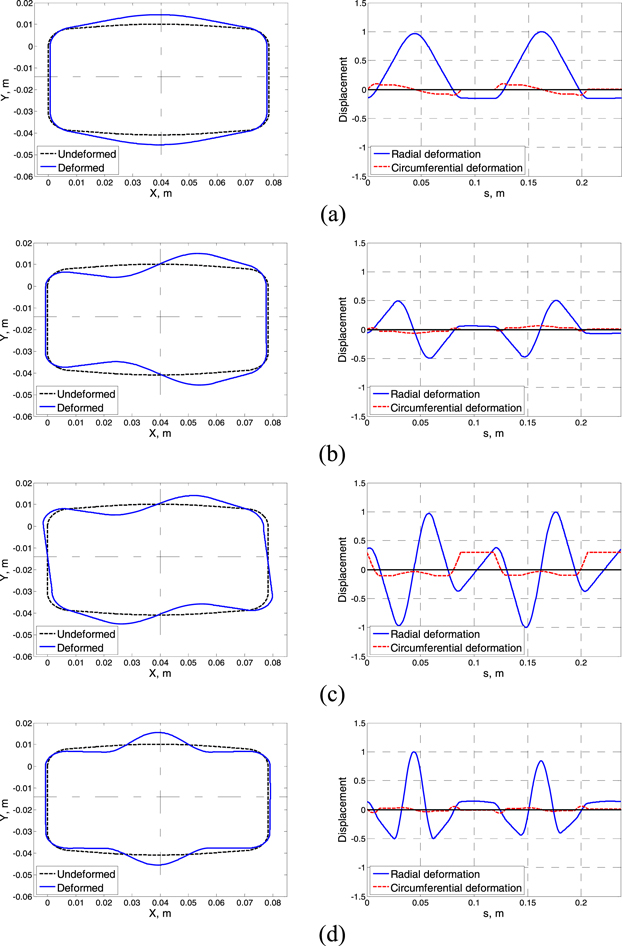
Figure 5. First four mode shapes: (a) first mode (symmetric) at 310 Hz; (b) second mode (anti-symmetric) at 726 Hz; (c) third mode (anti-symmetric) at 812 Hz; (c) fourth mode (symmetric) at 1080 Hz.
Download figure:
Standard image High-resolution image4. Experimental set-up and model validation
4.1. Open circuit dynamic stiffness
4.1.1. Experimental measurement
The experiment of the open circuit dynamic stiffness was achieved by measuring the acceleration transmissibility of a fabricated piezoelectric actuator with clamping mechanism designs described in table 3. Figure 6 shows the experimental set-up carried out to measure the dynamic stiffness of the actuator when it is inactive and harmonically excited by an external force in the frequency range of 0–1500 Hz. The bottom THUNDER element of the actuator was mounted on a base subjected to sinusoidal motion resulted from the excitation of an electrodynamic shaker (K2007E01). A mass of 100 g was attached to the top THUNDER element to vibrate freely along the vertical axis. The acceleration response and phase shift of the base and the mass were measured using small accelerometers (PCB 352B10). The transmissibility was obtained by taking the ratio of the acceleration of the mass  to the acceleration of the base
  The dynamic transmissibility of the system can be expressed in the frequency domain as:

where  is the dynamic transmissibility,
  is the dynamic stiffness,
  is the mass and
  is the excitation frequency. The actuator loss factor
  can be obtained using the measured reverberation time results
  at different frequencies. For example, the measured structural reverberation time of the actuator at 400 Hz was 0.23 s, as shown in appendix

Table 3. Geometrical and material properties of the fabricated clamping mechanism.
| Material | Width 
|
Hinge thickness 
|
Hinge radius 
|
Hinge opening angle 
|
Link thickness 
|
Link length 
|
Density 
|
Young's modulus 
|
Poisson's ratio | Loss factor |
|---|---|---|---|---|---|---|---|---|---|---|
| Aluminum 6061 | 14.0 | 0.70 | 8.5 | 84.5 | 2730 | 31.5 | 2700 | 69 | 0.33 | 0.02 |
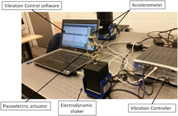
Figure 6. Experimental set-up of the open circuit dynamic stiffness test.
Download figure:
Standard image High-resolution imageThe variations of the measured transmissibility and phase shift are plotted in figure 7 in the frequency range up to 1500 Hz. It can be noticed from the figure that at low frequencies and under harmonic excitations, the piezoelectric actuator structure behaves roughly as a simple spring-damper system having a maximum transmissibility peak of around 1.05 corresponding to the frequency of 172 Hz. Above 250 Hz, additional small peaks exist and the variation of the dynamic transmissibility is weaker than that below 200 Hz. Also, above 1000 Hz the transmissibility value of the actuator is approximately constant and is around 0.0075, as shown in figure 7. By measuring the reverberation time, the loss factor of the actuator can be determined by applying equation (39), which yields 0.05 for all frequencies.
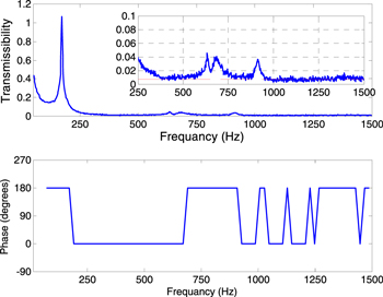
Figure 7. Variation of acceleration transmissibility and phase shift with frequency.
Download figure:
Standard image High-resolution image4.1.2. Analytical prediction
The analytical actuator model developed in section 3 is applied here to predict the structural dynamic stiffness of the actuator in the absence of the input voltage. Figure 8 is a graphical representation of the results of the analytical dynamic stiffness calculated for the fabricated THUNDER actuator system in the frequency range of 0–1500 Hz. Below 800 Hz and above 1100 Hz, the actuator system behaves as a soft structure with a dynamic stiffness range of 0.5–60 KN m−1. This result implies that the transmission of the kinetic energy through the actuator is very low, so that the designed actuator provides a weak structural path in this range of frequencies. However, the dynamic stiffness peak corresponding to the frequency of 970 Hz causes the actuator to act as a hard structural link and decreases the passive performance of the actuator.

Figure 8. Predicted dynamic stiffness plotted as a function of frequency for the fabricated actuator system.
Download figure:
Standard image High-resolution image4.1.3. Model validation
The validation of the analytical model derived here for studying the passive dynamic response of the designed actuator, in the absence of voltage, was performed by comparing the predicted dynamic stiffness with that measured experimentally, as shown in figure 9. It can be clearly seen that the present model agrees with the experimental results.

Figure 9. Comparison of the dynamic stiffness of the present model with the experimental measurements.
Download figure:
Standard image High-resolution image4.1.4. Velocity–force linearity test
The passive velocity–force linearity test of the piezoelectric actuator system was determined in the lab by measuring the output velocity as the force excitation is increased at a set of frequencies: 10, 50, 100, 250, 500 and 750 Hz. As shown in figure 10, the relation between the output velocity and input force are approximately linear at each frequency, which leads to the fact that, in the low frequency range, the piezoelectric actuator, when it is passive, behaves as a linear system.
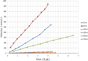
Figure 10. Variation of the free velocity response with force at frequencies of 10, 50, 100, 250, 500 and 750 Hz.
Download figure:
Standard image High-resolution image4.2. Free dynamic response
4.2.1. Experimental measurement
Two experiments were performed to determine the free dynamic response of the piezoelectric actuator. The first experiment was carried out to measure the free displacement and velocity at the midpoint of the top actuator when the actuator is simply supported at a single point located at the midpoint of the bottom actuator). In the second test, the free displacement and velocity of the midpoint of the top actuator was also measured, but when the actuator is clamped at two points located at the midpoint of the clamping mechanisms. The two tests were carried out by applying various sinusoidal voltages at different frequencies to the THUNDER elements without external force or moment excitations. As shown in figure 11(a), a voltage suppler (Tektronix AFG-3102) was used to generate input voltage signals to the actuator with a frequency range of 50–1500 Hz. The voltage signals were amplified up to 240 peak-to-peak volt using a voltage amplifier (TEGAM 2350) with a voltage gain of 50. The peak-to-peak free velocity at the midpoint of the top THUNDER element was measured using a laser vibrometer (Polytec OFV-5000) at different input voltages and frequencies. The velocity response was read directly from an oscilloscope connected to the vibrometer, while the free displacement was calculated by dividing the velocity response by  Figure 12 illustrates the measured frequency response of the free displacement and free velocity per unit voltage in decibels scale (dB).
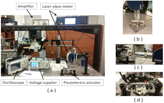
Figure 11. (a) Experimental set-up of the active free dynamic test; for (b) a vertically mounting actuator at one point; (c) a horizontally mounting actuator at one point; (d) a vertically mounting actuator at two points.
Download figure:
Standard image High-resolution image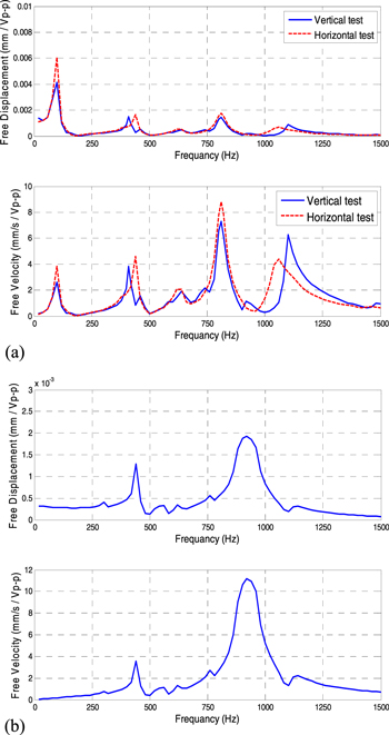
Figure 12. Free displacement and free velocity per unit voltage measurements carried out for: (a) a simply-supported actuator at a single point; (b) a clamp-supported actuator at two points.
Download figure:
Standard image High-resolution imageIn order to study the effect of the actuator weight on the measurements, the first experiment was carried out in two phases. The dynamic response of the actuator was first measured when the actuator vibrated along the vertical axis (parallel to the force of gravity), as shown in figure 11(b). Then, the measurements were performed again after installing the actuator in horizontal position (perpendicular to the force of gravity), as shown in figure 11(c). It can be clearly seen from figure 12(a) that the actuator weight influences not only the dynamic response value, but also the resonance frequency. For example, the second resonance at 400 Hz and the fourth resonance at 1100 Hz were shifted forward by 51 Hz and backward by 120 Hz, respectively, in the absence of the effect of gravity. Furthermore, the response of the free displacement and velocity per unit voltage in the horizontal test are higher than that in the vertical test at frequencies in the range of 0–1100 Hz. Although the analytical model predicts that there are only two resonances in the frequency range of 0–1500 Hz due the symmetric modes at 310 and 1080 Hz, the measurements show four resonances at 120, 380, 805 and 1050 Hz. This is due to the fact that, in the analytical model, it is assumed that the actuator is perfectly simply supported at the midpoint of the bottom THUNDER element. Thus, the first mode occurs at 0 Hz as a rigid rotational mode. However, the assumed boundary condition cannot be achieved in the actual experiment. In fact, the actuator was clamped by two parallel surfaces using plastic mounts to verify that the actuator vibrates in a direction parallel to the laser vibrometer. This clamping generates an internal reaction moment between the mount and actuator. Therefore, the first rigid rotational mode at 0 Hz was shifted to 120 Hz as a flexural mode, and also the mode resonance at 310 Hz was shifted forward to 380 Hz. Note also that the curves show a peak at the second anti-symmetric mode (805 Hz) due to the excitation of this mode.
4.2.2. Model validation
As shown in figure 13(a), there is general agreement in the trend of the analytical model with experimental results. In fact, the excitation of the second anti-symmetric mode and the shift of the first mode significantly affected the model validation. Thus, there is a slight divergence between the analytical and experimental results around 18 dB at frequencies between the first and second peaks and there is one around 10 dB at the second anti-symmetric mode. In order to check the accuracy of the present model, the assumed boundary conditions in the analytical model should be identical with that in the experiment. Hence, further validation tests were performed by comparing the results obtained by the analytical model with the measurements of the second experiment, as discussed in section 4.2.1. As mentioned previously, the actuator was clamped at two points at the clamping mechanism instead of at a single point at the bottom THUNDER element. Here, it can be guaranteed that the actuator vibrates perfectly along the vertical axis and the anti-symmetric modes are not excited. As shown in figure 13(b), the measured results for the free displacement and free velocity per unit voltage demonstrate an excellent agreement with the analytical results.

Figure 13. Comparison of the free displacement and velocity per unit voltage results of the present model with measurements carried out for: (a) a simply-supported actuator at a single point; (b) a clamp-supported actuator at two points.
Download figure:
Standard image High-resolution image4.2.3. Velocity–voltage linearity test
To check the velocity–voltage linearity of the piezoelectric actuator system, the free dynamic response was measured by amplifying the voltage applied to the actuator at different frequencies (10, 50, 100, 250, 500, 750, 1000, 1250 and 1500 Hz). As illustrated in figure 14, the velocity–voltage curves increase approximately linearly as the actuation voltage is increased for all frequencies except for the frequency of 750 Hz, where the actuator behaves as a nonlinear system. In fact, the nonlinear response of the actuator velocity at 750 Hz occurs due to the excitation of the non-symmetric mode corresponding to the natural frequency of 805 Hz, as shown in figure 13(a). Although it is expected that the excitation of the non-symmetric modes should be completely absent, the appearance of these modes could be attributed to three reasons:
- The actuator was not mounted exactly at the midpoint or shifted from the midpoint during the experiment.
- The applied voltage was not perfectly uniform over the electrodes.
- The actuator structure itself was not symmetrical.
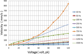
Figure 14. Variation of the free velocity response with exciting voltage at frequencies of 10, 50, 100, 250, 500, 750, 1000, 1250 and 1500 Hz.
Download figure:
Standard image High-resolution imageHowever, in general, the results in this section and section 4.1.4 reveal that the piezoelectric actuator can be considered as a linear system in the actuating frequency range of 0–1500 Hz.
4.3. Blocked force
The blocked force characteristic of a piezoelectric actuator describes the maximum actuating force when the system is completely blocked and there is no dynamic response. The blocked force can be measured experimentally using a force sensor and can be also obtained using the measured actuator parameters: free displacement and dynamic stiffness. Since the actuator system is approximately linear, the mechanical and electrical properties of the actuator can be coupled into a single linear equation as,

where  are the displacement, mechanical force and electrical voltage, respectively. The frequency constants
  are the displacement per unit force (the inverse of the measured dynamic stiffness) and the displacement per unit voltage (the measured free displacement), respectively. The actuating force function can be obtained by rearranging equation (40) to be given as,

where  is the complex dynamic stiffness. By blocking the actuator, the displacement along the vertical axis is zero for all actuating frequencies. Thus, equation (41) can be rewritten as,

where the frequency constant  is the blocked force per unit voltage. Using equation (42) and the measured data, the blocked force can be calculated at different frequencies.
5. Parametric study
For the actuator designs, the developed model, discussed in section 3, is applied here in order to investigate the active and passive characteristics and discuss the influence of structural parameters on actuator device performances. As shown in figure 3, the clamping mechanism is constructed of two in-plane fixable hinges at the corners as well as two grippers at the ends and a solid link. However, the configuration of the hinges is the critical part in the design of the actuator device and plays an important role in the control of passive and active performances. The flexible hinges have been designed in a curved-shape with rounded corners, as shown in figure 15. In the current investigation, the material properties and width of the clamping mechanism are considered to be fixed, however, the curved-hinge parameters that have considerable effects on the bending rigidity and arc length, such as the thickness t, radius R and opening angle α, are varied as defined in table 4. Thus, the theoretical model is applied in this study to quantify the influence of these geometrical parameters on the free dynamic response and blocked actuating force per unit voltage, when the actuator is active, as well as the passive dynamic stiffness.
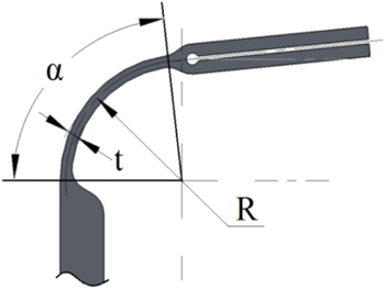
Figure 15. Configuration of flexible hinge design.
Download figure:
Standard image High-resolution imageTable 4. Geometric parameters of flexible hinge design.
| Set | Hinge design | Thickness (mm) | Radius (mm) | Opening angle (degree) | Width (mm) |
|---|---|---|---|---|---|
| I | 1 | 0.30 | 8.00 | 84 | 14.0 |
| 2 | 0.50 | ||||
| 3 | 0.75 | ||||
| 4 | 1.00 | ||||
| II | 5 | 0.75 | 4.00 | 84 | |
| 6 | 6.00 | ||||
| 7 | 8.00 | ||||
| 8 | 10.00 | ||||
| III | 9 | 0.75 | 8.00 | 78 | |
| 10 | 80 | ||||
| 11 | 82 | ||||
| 12 | 84 | ||||
5.1. The effects of thickness on the actuator properties
A parametric study is performed in this section to investigate the effects of the hinge thickness, by obtaining the frequency response of the free displacement, blocked force and dynamic stiffness of an actuator design. Four hinge designs are selected with identical material and geometrical parameters, but various thicknesses, as defined in table 4. Four thickness—0.3, 0.5, 0.75 and 1.0 mm—are given to the hinge designs: 1, 2, 3 and 4, respectively, to represent four different types of static hinge flexibility: very soft, soft, medium and hard. The frequencies corresponding to the symmetric and anti-symmetric modes of the four actuator designs are calculated using the analytically model and listed in table 5. Note that the frequency values corresponding to the first symmetric modes are shifted forward to higher frequencies as hinge thickness is increased. Single symmetric mode exists in the frequency range up to 1000 Hz for all the present designs except the very soft one which has two symmetric modes.
Table 5. Natural frequencies corresponding to the lower symmetric and anti-symmetric mode shapes of the actuator structure.
| Hinge design | Thickness (mm) | Symmetric resonances (Hz) | Anti-symmetric resonances (Hz) |
|---|---|---|---|
| 1 | 0.30 | 128, 740, 1109 | 436, 516, 1040 |
| 2 | 0.50 | 185, 1252, 1423 | 525, 585 |
| 3 | 0.75 | 285, 1414, 1510 | 644, 685 |
| 4 | 1.00 | 393, 1490, 1598 | 807, 815 |
Figures 16(a)–(c) demonstrate the influence of the hinge thickness variation on the results of the free displacement, blocked force and dynamic stiffness of the actuator device in the frequency range of 0–1000 Hz. As predicted, hinge thickness significantly affects the dynamic stiffness values of the actuator device at low frequencies, in particular, below the fundamental resonance frequency. As shown in figure 16(a), below the first dips, which correspond to the first symmetric modes, the dynamic stiffness–frequency curves of the four designs are approximately constant. Furthermore, as the hinge thickness decreases, the results of the passive dynamic stiffness are plotted in lower levels, which imply an increase in structural flexibility of the actuator. Therefore, the active free displacement per unit voltage is improved in this frequency range, as shown in figure 16(b). Above the first resonance frequencies, the stiffness curves rise slightly and approximately linearly with slope of about 0.03 dB Hz−1 as the frequency is increased. Interestingly, the hinge thickness effect on actuator flexibility is reflected at high frequencies, so that the reduction in thickness causes an increase in the dynamic stiffness because of the 180° phase shift occurring at the first modes, as illustrated in figure 17. The graphical representations in figures 17(a)–(d) illustration the phase shifts occurred between the input force with output passive displacement and the applied voltage with active displacement for the four actuator models. The results shown in the figures clearly demonstrate that there is an approximate correlation between the phase shift of the active and passive dynamic responses at frequencies before the peaks in curves of the dynamic stiffness. However, this correlation is obviously absent at higher frequencies. The free displacement describes the ratio of the active displacement response at the plastic mounts to the electrical excitation value, while the dynamic stiffness is the ratio of the mechanical excitation value to the passive displacement response. Thus, the displacement is inversely proportional to actuator hardness, as can be clearly observed by comparing the curves in figure 16(a) with those in figure 16(b). It can be seen that first dip point on a stiffness–frequency curve of a specified thickness, resulting from the first symmetric resonance, turns to a peak point on the corresponded displacement–frequency curve. At frequencies above the first symmetric modes, a slight and approximately linear reduction in free displacement curves occurs with increasing frequency or decreasing hinge thickness.

Figure 16. Effects of hinge thickness on the actuator properties: (a) dynamic stiffness, (b) free displacement, and (c) blocked force.
Download figure:
Standard image High-resolution image
Figure 17. Phase shifts plotted for the displacement versus the input force and voltage when the hinge design is: (a) 1, (b) 2, (c) 3 and (d) 4, as described in table 4.
Download figure:
Standard image High-resolution imageFor the blocked force, as the hinge thickness increases, the location of the peaks in the blocked force versus frequency curves, which correspond to the peaks in curves of the dynamic stiffness, shift to higher frequencies because of the flexibility effect. Below these peaks, the blocked force values are approximately constant (independent of frequency) and also increase to higher levels as the thickness is increased. Thus, to advance the blocked force of an actuator without dips at low and high frequencies, the hinge thickness must be increased, although it may adversely affect the performance of the free dynamic response, particularly at low frequencies. Note that, for a simple spring actuator system, the blocked force  can be mathematically defined as the product of the absolute values of the free displacement
  and dynamic stiffness
  or, as another definition, the summation of the magnitudes of the free displacement and dynamic stiffness in decibel scale at each frequency,


Thus, the results of the blocked force versus frequency, which are obtained from equation (44), can be analyzed considering this simple description. At frequencies below 500 Hz, the blocked force levels remain unchanged with frequency although both the free displacement and dynamic stiffness curves are characterized by having dips and peaks in this frequency range. In fact, the curves of the free displacement and dynamic stiffness are approximately symmetrical. Thus, the dips and peaks cancel each other out, producing straight lines. However, this symmetry is almost nonexistent at higher frequencies, so that the curves are characterized by peaks at frequencies corresponding to the peaks in dynamic stiffness curves. The two blocked force dips at 665 and 980 Hz of the very soft and soft actuator designs result from the effect of the free displacement at those locations. From the above analysis, it can be concluded that, for engineering applications which require high dynamic responses at low frequencies or high static displacement, ideal actuators must be designed to have very soft hinges at the corners. At frequencies below 100 Hz, for example, an actuator device with a hinge thickness of 0.3 mm can generate free displacement of about  at its maximum input voltage
  On the other hand, if the actuators are to be used in a system to provide high actuating force in wide range of frequencies, the actuator hinges should be designed with a thicker cross section in order to increase the in-plane hinge rigidity. Thus, the greatest predicted actuating force per unit voltage in the present actuator set is about
  which can be achieved using the hinge design with a thickness of 1 mm.
5.2. The effects of radius on the actuator properties
Although the linear flexural rigidity of the hinges is not affected by changes in their radii, a variation in hinge radius increases or decreases the curvature length of the hinges and thereby the flexibility of the actuator device. In order to quantify the influence of hinge radius on actuator efficiency, the active and passive performances are plotted in figure 18 and then analyzed for a set of four hinges designs (5, 6, 7 and 8) having different hinge radii of 4, 6, 8 and 10 mm, as demonstrated in table 6. Comparing the results of set II (hinges designs 5–8) with those of set I (hinges designs 1–4), it can be generally noticed that the curves plotted for set II are more convergent than the curves of set I. This implies that variation in hinge thickness has greater impact on actuator flexibility than variation in hinge radius because of the linear flexural rigidity effect. Figures 18(a)–(c) reveal the obtained results of the free displacement, blocked force and dynamic stiffness of the actuator device up to 1000 Hz. At low frequencies, particularly below the first resonances, the improvements in dynamic stiffness and free displacement achieved by increasing the hinge radius is insignificant, as shown in figures 18(a) and (b). However there is a notable effect of increasing the hinge radius on the locations of peaks and dips. The peak and dip positions of the smaller hinge radii are shifted to higher frequencies due to the effects of the phase shift. In fact, the first out-of-phase shift between input excitation and output displacement occurs at lower frequencies with increasing hinge radius. This shift causes also a backward shift in the curve and thereby a lack of improvement in free dynamic response and dynamic stiffness at higher frequencies. Note that the blocked force curves are nearly linear at frequencies up to 700 Hz because of the effect of the high symmetry of the dynamic stiffness and free displacement. At higher frequencies, however, intense peaks and dips exist, which indicate shifts between frequencies corresponding to out-of-phase shifts in dynamic stiffness curves and those in free displacement curves. The blocked force predictions also demonstrate the considerable influence of the hinge radius on the actuating force performance. As shown in figure 18(c), as the hinge radius is decreased, the blocked force improves for frequencies below about 750 Hz, and the location of the peaks shifts to higher frequencies for frequencies above 750 Hz.

Figure 18. Effects of hinge radius on the actuator properties: (a) dynamic stiffness, (b) free displacement, and (c) blocked force.
Download figure:
Standard image High-resolution imageTable 6. Natural frequencies corresponding to the lower symmetric and anti-symmetric mode shapes of the actuator structure.
| Hinge design | Radius (mm) | Symmetric resonances (Hz) | Anti-symmetric resonances (Hz) |
|---|---|---|---|
| 5 | 4 | 341, 1622, 1628 | 636, 887 |
| 6 | 6 | 320, 1508, 1571 | 691, 740 |
| 7 | 8 | 285, 1414, 1510 | 644, 685 |
| 8 | 10 | 252, 1320, 1453 | 573, 656 |
5.3. The effects of opening angle on the actuator properties
The influence of the opening hinge angle on the active and passive properties of an actuator with selected values of opening angles  is discussed in this section. Again, the developed model is applied to four hinge designs, as detailed in table 4, in order to determine the predictions of the dynamic stiffness, free displacement and blocked force, as plotted in figures 19(a)–(c), respectively. Although the THUNDER piezoelectric curvature property has no effects on the thickness and radius of actuator hinges, the variation of the opening angle is not independent from it. As shown in table 7, the value of the opening angle increases when the piezoelectric curvature is decreased. The curves in figure 19(a) demonstrate that the dynamic stiffness values are not considerably affected by the hinge opening angle variation, although the increase in the opening angle moves the dynamic stiffness dips, which correspond to the first resonant frequencies, slightly forward into higher frequencies. Table 7 shows that as the opening angle is increased by
  the first symmetric resonant frequency increases by around 15 Hz. Below the first resonances, there is a considerable effect of the opening angle on the values of the free dynamic response. As shown in figure 19(b), the decrease in the opening angle improves the free dynamic performance in this frequency range, however, the variation of the opening angle is not very influential on the values at frequencies exceeding the first resonances. The results presented in figure 19(c) demonstrate that the influence of the opening angle on the blocked force characteristic is noticeable, particularly at frequencies below the dynamic stiffness peaks, in which the direction of the forces at the mounts are opposite (out-of-phase). Considering the curves in figures 19(a) and (c), the location of the maximum blocked force per unit of voltage continuously correspond to the dynamic stiffness peaks, which is around 1.6 N V−1 at frequency of 850 Hz.

Figure 19. Effects of hinge opining angle on the actuator properties: (a) dynamic stiffness, (b) free displacement, and (c) blocked force.
Download figure:
Standard image High-resolution imageTable 7. Natural frequencies corresponding to the lower symmetric and anti-symmetric mode shapes of the actuator structure.
| Hinge design | Opening angle of actuator hinge (degree) | Curvature of piezoelectric element (m−1) | Symmetric resonances (Hz) | Anti-symmetric resonances (Hz) |
|---|---|---|---|---|
| 9 | 78 | 10.83 | 242, 1405, 1487 | 649, 703 |
| 10 | 80 | 9.08 | 257, 1413, 1497 | 648, 697 |
| 11 | 82 | 7.31 | 272, 1414, 1505 | 646, 691 |
| 12 | 84 | 5.49 | 286, 1415, 1510 | 644, 685 |
6. Conclusions
In this paper, a new configuration of a piezoelectric actuator is proposed, and a mathematical model is developed to describe the active and passive characteristics and the influence of geometrical parameters on the actuator performance per unit of mechanical and electrical excitation. The designed actuator can be efficiently used as a passive isolator and active force generator in active-passive control systems and many smart structural applications. The actuator consists of a pair of THUNDER elements attached to each other using two aluminum clamping mechanisms, which are constructed of in-plane fixable hinges at their corners, grippers and rigid links. A particular actuator design with hinge dimensions of  is fabricated and its mechanical and electrical properties are experimentally measured to check the validity of the mathematical model. A parametric study is performed using the developed model to quantify the effects of the geometrical parameters of the fixable hinges on the active and passive actuator properties: dynamic stiffness, free displacement and blocked force. Three sets of actuator models with identical materials, widths and THUNDER element models (TH-8R) and different geometrical hinge parameters—thickness, radius and opening angle—are examined in the parametric study.
The frequency characteristic curves of dynamic stiffness reveal that the hinge thickness parameter has a greater effect on passive isolation of the actuator than the radius and opening angle do in frequencies up to 1000 Hz. Furthermore, the influence of the opening angle on the dynamic stiffness values as well as their peaks and dips is weak and, at some frequencies, negligible. This can be attributed to the fact that the opening angle does not significantly change the actuator configuration, and also the firs symmetric resonances are almost convergent when the opening angle is varied from  Considering the parametric study of the actuator set I (hinge designs 1–4), it can be concluded that the thickness parameter controls the actuator hardness level so that the given thicknesses represent four different types of static hinge flexibility: very soft, soft, medium and hard. Also, for set II (hinge designs 5–8), the increase or decrease in the hinge radius directly affects the length of the hinge curvature, leading to an overall increase or decrease in the flexibility of the actuator device. Generally, the predicted results show that, as actuator hardness is increased, the locations of the peaks and dips shift to higher frequencies and the blocked force performance is improved. Thus, the hinge actuator designs with a thickness of 1.0 mm in set I and radius of 10 mm in set II provide the highest blocked force average. For the free dynamic response, a high level of free displacement can be obtained at low and high frequencies using the hinge dimensions of 0.75 mm thick and a radius of 10 mm. Since the hinge opening angle and the THUNDER piezoelectric curvature are strongly related, the effects of the piezoelectric curvature can be analyzed by considering the opening angle results. The results show that an increase in the curvature of the THUNDER elements improves the active capabilities of the actuator, though the passive insulation characteristic may be adversely affected when the curvature is increased. Thus, a significant improvement in the performance of the actuator can be achieved by optimizing the THUNDER elements curvature.
Although the novel piezoelectric actuator model presented in this paper has been developed for an ASAC system for controlling the low frequency sound transmitted through a double-panel structure, the actuator model provides ideal solutions for many engineering applications that require an integrated active and passive control systems.
Appendix A.: Mechanical and electromechanical properties of the actuator structure
- 1.The physical properties of the actuator system
- 2.The electromechanical properties of the actuator system
- 3.The entries of the sub-mastics
- 4.The entries of the sub-vectors


Appendix B.: Reverberation time of the fabricated actuator at 400 Hz
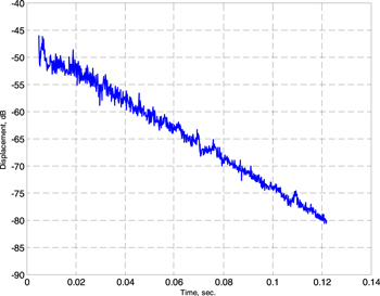
Figure B1. Reverberation time in seconds at the excitation frequency of 400 Hz.
Download figure:
Standard image High-resolution image