

Abstract
Rising internal temperature in the working process affects the stiffness and damping of the magnetorheological elastomer (MRE) isolator, which leads to decrease of stability. In this paper, temperature characteristics of a laminated MRE isolator are studied. Firstly, the structure of the MRE isolator is introduced and the dynamic mechanical properties of the MRE samples under various temperatures are tested. Secondly, a temperature experiment is carried out on the MRE isolator to explore the relationship of the resonant frequency, stiffness and damping with the temperature. The experimental results indicate that after working for 145 min with 3 A current, the internal average temperature of the MRE isolator tends to be stable and increases by 219.92% compared with not working. A sine sweeping-frequency experiment demonstrates that the maximum attenuation of the resonant frequency can reach 13.85% with the temperature increasing from 30 °C to 80 °C. Moreover, the maximum attenuations of the stiffness and the damping are 26.42% and 34.55% respectively. Finally, a method using silicon grease and air cooling is proposed to reduce the temperature by 41.6 °C in 145 min, which can effectively improve the stability of the MRE isolator.
Export citation and abstract BibTeX RIS
1. Introduction
With the increasing demands of environmental comfort, the influence of vibration on many fields such as building [1], vehicle [2], precision-fabrication and precision measurement [3, 4] is more and more obvious. However, due to the complexity and volatility of environmental vibration, the traditional vibration isolation devices that are quite effective on design goals have been unable to meet the requirements of modern vibration isolation [5].
The appearance of magnetorheological (MR) material provides a prerequisite for the development of new intelligent vibration isolation, and also becomes a choice to solve the current problem encountered in vibration isolation. As members of the MR materials, magnetorheological fluid (MRF) [6, 7] and MRE [8, 9] have been investigated by many scholars due to their excellent magnetic control characteristics. At the same time, many MR devices applied in the field of vibration control have been designed and manufactured, including MRF dampers [10, 11], MRE isolators [5, 12–16] and MRE absorbers [17–20]. However, the dependence of MR devices on the magnetic field makes the heating become an inevitable problem.
During the working process, the change of temperature inside MR devices is very large compared with their initial state. In order to study the influence of internal temperature on the performance of the device, a lot of research has been set under way. Bajkowski et al [21] studied energy dissipation in the MR damper, considering the impact of temperature caused by friction forces and coil heating, and proposed an innovative rheological model with differential equations of motion to describe the mechanical properties of MR dampers at different temperatures. McKee et al [22] explored the effects of temperature on performance of a compressible MR fluid damper-liquid spring suspension system, and testing results indicated that the compressibility of MR fluid was proportional to the fluid temperature, while the viscosity of the MR fluid was inversely related to the fluid temperature. Gordaninejad et al [23–25] presented theoretical and experimental studies on heat generation and dissipation in MR fluid shock absorbers, and proposed a theoretical model to predict the temperature increase in MR fluid dampers. Wilson et al [26] built and characterized an MR fluid damper for the driver/commander seat to study its changes in characteristics as operating temperature increased from 0 °C to 100 °C, and experimental results showed that the controllable yield force decreased by 20% and the post-yield damping decreased by over 60%. Moreover, a new model was proposed to better capture stiffness behavior of the MR fluid damper over a large operating temperature range. Dogruoz et al [27] developed a theoretical model of an MRF damper incorporating a lumped system approach for the prediction of the temperature and the corresponding peak force values with a sinusoidal input motion, and a series of experiments were carried out to prove the accuracy of the model. Because the MRF technology is mature and the MRF damper is also widely used in practical engineering, research on the temperature of MR devices is mainly focused on the MRF damper.
The self-heating of MRF dampers will reduce their stability, which may lead to premature failure of the system [22, 23, 26]. Compared with MRF devices, i.e. MR dampers, MRE devices normally need larger coils to provide enough magnetic field for MRE, particularly for a large-scale MRE device, and this means that MRE devices have more serious issues with heating [28]. Up to now, researches on MRE devices have mainly focused on design and testing [5, 16–20, 29–32], modeling [33–38] and control [12–15, 39], while the thermal effects on MRE devices have not been studied. This will not be conducive to the application of MRE devices in practical engineering fields such as building isolation [5, 15] and seismic mitigation of bridge superstructures [16]. Therefore, it is very significant to study the effect of self-heating on the performance of MRE devices for their application in the engineering field.
In this paper, we study the heating of a laminated MRE isolator and discover its non-uniform temperature distribution in the working area, which has not been discussed in detail in previous research. Changes in the resonant frequency, stiffness and damping with the internal temperature are discussed to prove that heating can cause adverse effects on their stability and the working width of the frequency. Ultimately, an economical and effective cooling measure is employed to effectively reduce the internal temperature and improve the stability of the MRE isolator, which enhances the feasibility of its use in engineering applications.
The MREs used for the laminated structure in this paper are fabricated and tested with different temperatures; the structure of the MRE isolator is described in section 2. Then, the temperature testing system is set up to measure the temperature characteristics of the MRE isolator and the relationship of the resonant frequency, stiffness and damping with the temperature is presented in section 3. Next, aiming at the serious heating phenomenon of the MRE isolator, air cooling, as an effective and economical method, is proposed to reduce the internal temperature in section 4. Finally, the experimental results are discussed, and the effectiveness of the experiment is demonstrated in section 5.
2. Structure of the MRE isolator
2.1. Preparation of MREs
In this work, room temperature vulcanizing (RTV) silicon rubber (Model SC-2110, Beijing Sanchen Industrial New Material Co., Ltd, China) was chosen as the MRE matrix. Soft magnetic carbonyl iron particles (CIP, Model JCF2-2, d = 5 ∼ 8  Jilin Nichkel Industry Co., Ltd, China) were used as the filling particles, while silicone oil was used as the plasticizer. The mass fractions of CIP, RTV silicon rubber and silicon oil were 70%, 15% and 15%, respectively. After being stirred for 25 min, with the viscosity of reactants increasing obviously, the mixture of CIP, RTV silicon rubber and silicone oil was placed in a vacuum oven to remove air bubbles and then poured into aluminum molds. Eventually, after curing for 24 h under a constant magnetic field of 0.7 T, MRE samples used for the isolator were prepared completely.
The dynamic mechanical properties of the MRE samples with various temperatures (30 °C, 50 °C, 70 °C, 90 °C) and strain of 0.1% investigated using an advanced rheometer (Model MCR301, Anton Paar, Austria) are presented in figure 1. The testing frequency is 10 Hz and the magnetic flux densities increase from 0 to 0.85 T. Figure 1(a) gives the relationship between the shear storage modulus and the magnetic flux density, where the shear storage modulus increases nonlinearly with increasing magnetic flux densities and decreases with increasing temperature. The stable shear storage modulus with the temperature of 90 °C at 0.85 T is 1.01 MPa, which is attenuated by 28.37% compared with the modulus of 1.41 MPa for 30 °C. Moreover, figure 1(b) presents the shear loss modulus versus magnetic flux density under different temperatures, in which the maximum shear loss modulus is 0.1 MPa at 90 °C, a reduction of 33.70% compared with 30 °C. Accordingly, high temperature will reduce the shear storage modulus and shear loss modulus of RTV silicon rubber based MRE samples for the high temperature softening of the MRE matrix.
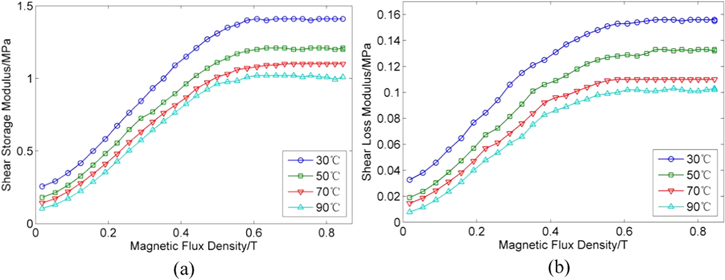
Figure 1. Dynamic mechanical properties of the MRE samples versus magnetic flux density with different temperatures and strain of 0.1%: (a) the shear storage modulus curves and (b) the shear loss modulus curves.
Download figure:
Standard image High-resolution image2.2. Structure description of MRE isolator
Figure 2 gives the structural configuration diagram of the MRE isolator used for lateral vibration suppression of the bridge monitoring equipment; it is similar to the structure of traditional rubber bearings[40, 41], which can greatly enhance vertical bearing capacity. It consists of six layers of MREs with 2 mm thickness bonded to five layers of thin steel plate with 1 mm thickness by homemade silicone rubber adhesive. The laminated MREs are placed in the centre of an electromagnetic coil, which provides a uniform magnetic field when current is passed through it. The coil, whose electric resistance is 3 Ω, is made of copper with diameter of 0.8 mm and wound on a coil bobbin. The distance between the laminated MREs and the coil bobbin gives the MRE isolator a maximum deformation of 4 mm. In order to improve the stability of top cover and increase the vertical carrying capacity of the laminated MRE isolator, a small gap between the top cover and the steel sleeve is designed, where 80 steel balls are evenly distributed.
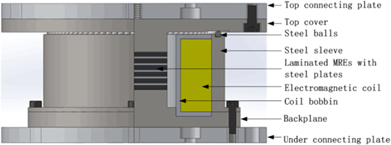
Figure 2. Section-view of the laminated MRE isolator.
Download figure:
Standard image High-resolution imageThe maximum power  of the coil under maximum operating current
  of 3 A is represented by

where  is the electric resistance of the coil. The maximum power
  can reach 27 W, ignoring the impact of temperature on the electric resistance. As a result, the heating of the coil will be very significant with 3 A current for a long working time.
Figure 3 gives the magnetic flux density and magnetic flux path under the excitation current of 3 A by Ansoft Maxwell. The result of figure 3(a) indicates that the distribution of magnetic field is uniform under the working area of the laminated MREs with the magnetic flux density of 420 mT. Figure 3(b) shows that the magnetic lines of flux pass perpendicularly and uniformly through the cross-section of the laminated MREs, in order to ensure that the working area has the most effective magnetic field.
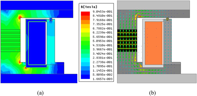
Figure 3. Electromagnetic simulation: (a) magnetic flux density and (b) magnetic flux path.
Download figure:
Standard image High-resolution image3. Effect of temperature on the MRE isolator
3.1. Temperature measurement
The performance of MREs will change with the environmental temperature, which determines the stability of MRE isolators in different temperature environments. Nevertheless, the internal temperature of the MRE isolator will be increased due to the heating of the coil in the running process. Therefore, it is necessary for the MRE isolator to monitor its internal temperature and a temperature measurement system is set up as shown in figure 4(a) for this purpose. Three spherical temperature probes of a thermocouple thermometer (Model F-8855, Shenzhen Frank Electronic Co., Ltd, China) with diameters of 1 mm, shown in figure 4(b), are fixed between the MRE and the steel sheet. The specific arrangement of five measuring points is displayed in figure 5, where the temperature at each layer of the MRE is obtained by taking the mean value of points a, b and c. During the experiment, a DC power (Model WYK-305B, EAST Electric Power System Technology Co., Ltd, China) is employed to supply 3 A current to the MRE isolator for 145 min and the data of temperature are recorded every 5 min.

Figure 4. Temperature measurement of the MRE isolator: (a) test system and (b) photo of temperature probes.
Download figure:
Standard image High-resolution image
Figure 5. The arrangement of the temperature measuring points.
Download figure:
Standard image High-resolution imageThe temperature-time curves shown in figure 6 illustrate that the data from the five measuring points increases nonlinearly with the increase of time and decreases with increasing measuring point number. Because the metal has good thermal conductivity, the heat will be transferred through the backplane to the lowest MRE, which will cause the temperature of the lowest MRE to rise quickly. However, when the thermal equilibrium is reached, the temperature of each layer of MRE is basically the same. This non-uniform temperature distribution will make the performance of each layer of MRE different, thus temperature compensation is required in further study to provide the same working environment for laminated MREs. The average temperature of the laminated MREs is consistent with the data from measuring point 3 and also has an obvious rise with the continuous operation of the MRE isolator, 26.6 °C for 0 min and 85.1 °C for 145 min, which increases by 219.92%. The testing results show that heating of the coil has a great influence on the temperature of the isolator. The total energy produced by the coil can be calculated by:

where  is the total energy,
  is the current in the coil,
  is the coil resistance,
  is the running time,
  is the total mass of the MRE isolator,
  is its specific heat capacity,
  and
and  are the current temperature and initial temperature respectively. Formula (2) indicates that there is a positive proportional function between current temperature and running time. However, due to the heat exchange between the surrounding air and the sleeve of the MRE isolator, this linear relationship is destroyed. With the increase of ambient air temperature, the heat exchange between the two parts becomes weaker, until a state of equilibrium is reached. At this moment, the internal average temperature will reach a stable value (about 85.1 °C for 145 min).

Figure 6. Internal temperature of the MRE isolator versus time.
Download figure:
Standard image High-resolution image3.2. Experimental study of the resonant frequency with temperature
Experimental results prove that the interior temperature of the MRE isolator will increase rapidly after a long period of work. In order to further understand the effect of temperature on characteristics of the isolator, a sine sweeping-frequency vibration method is adopted to evaluate its transmissibility at different temperatures. The resonant frequency, the stiffness and the damping of the prototype can be obtained to characterize its performance.
3.2.1. Experimental setup
Figure 7 gives the experimental setup for the evaluation of properties of the MRE isolator at various temperatures. The sine sweeping-frequency waveform produced by a signal generator (Model 33120A, Agilent, USA) is amplified by a power amplifier (Model YE5874, Sinocera Piezotronics, China) to drive an electromagnetic exciter (Model JZK-50, Sinocera Piezotronics, China). A horizontal sliding table constructed by ourselves is connected with the exciter to form a complete excitation system. The MRE isolator is installed on the sliding table and moves along with it. Two accelerators (Model 333B52, Piezotronics, USA) are arranged on the surface of the sliding table and the top cover to measure the excitation and response signals. Two kinds of signals are collected by a data acquisition instrument (Model MDR-05, Beijing Aerostandard New Technology Company, China) and transferred to a computer. Meanwhile, the DC power is used to supply DC current and change the internal temperature recorded by the thermocouple thermometer whose probes are arranged at measuring point 3 in real time for the MRE isolator.

Figure 7. Photo of the sine sweeping-frequency vibration system for the MRE isolator.
Download figure:
Standard image High-resolution imageFor all tests, a sine sweeping-frequency excitation within a range from 5 Hz to 40 Hz was chosen to test the transmissibility of the MRE isolator, while DC current was independently altered from 0 A to 3 A in 1 A increments. A set of tests were carried out at intervals of 10 °C as recorded by the thermometer; the initial and final temperatures were 30 °C and 80 °C respectively.
3.2.2. Analysis and discussion of results
The magnitude-frequency curves of transmissibility with different currents under the conditions of high temperature (80 °C) and low temperature (30 °C) are displayed in figure 8. As is shown in the figure, the resonant frequency of the MRE isolator at high temperature is smaller than that at low temperature with the same current, while the peak of transmissibility is higher. The parameters of the MRE isolator, such as stiffness and damping, with the mass of 0.5 kg under different currents can be identified based on the test results and the formulas in [16, 31].
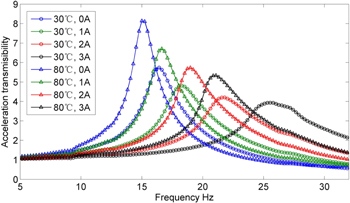
Figure 8. Magnitude-frequency curves of transmissibility with temperatures of 30 °C and 80 °C.
Download figure:
Standard image High-resolution imageFigure 9 presents the relationship of the resonant frequency and temperatures with several applied currents. It can be seen that the frequency decreases linearly with the increase of the internal temperature and the decreasing trend of different currents is basically consistent. Figure 10 gives the curves of different frequencies versus currents at several temperatures, which shows the nonlinear increase with consistent trend. Besides, the higher the temperatures are, the lower the resonant frequencies, which is consistent with the result shown in figure 9.
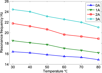
Figure 9. Resonant frequency of the MRE isolator versus temperature with different currents.
Download figure:
Standard image High-resolution image
Figure 10. Resonant frequency of the MRE isolator versus current with different temperatures.
Download figure:
Standard image High-resolution imageAll of the testing data are listed in the table 1. The maximum attenuation of the resonant frequency reaches 13.85% with the current of 3 A, while the temperature increases from 30 °C to 80 °C. Furthermore, as the temperature rises, the maximum increase of the frequency caused by currents will be attenuation and this phenomenon shows that high temperature can reduce the working width of the MRE isolator's frequency.
Table 1. Resonant frequency (Hz) of the isolator with various currents and temperatures.
| Currents (A) | |||||
|---|---|---|---|---|---|
| Temperature (°C) | 0 | 1 | 2 | 3 | Increase (0–3 A) |
| 30 | 16.38 | 18.48 | 21.78 | 24.41 | 49.02% |
| 40 | 16.17 | 18.08 | 21.23 | 24.00 | 48.42% |
| 50 | 15.84 | 17.73 | 20.64 | 23.13 | 46.02% |
| 60 | 15.50 | 17.03 | 19.66 | 22.56 | 45.55% |
| 70 | 15.31 | 16.63 | 19.28 | 22.00 | 43.69% |
| 80 | 14.88 | 16.16 | 18.88 | 21.03 | 41.33% |
| Attenuation(30–80 °C) | 9.16% | 12.55% | 13.31% | 13.85% | |
The resonant frequency of the MRE isolator is mainly influenced by its internal temperature and the excitation current, which has been demonstrated by the test results. The relationship between the resonant frequency, the temperature and the excitation current can be described by the following equation:

where  is the resonant frequency,
  is the excitation current,
  is the internal temperature, and

 ,
,  and
and  are corresponding parameters. Based on the equation, it is found that when the excitation current is certain, there is a linear function between the internal temperature and the resonant frequency.
  is the slope of the function and
  represents the initial resonant frequency. On the other hand, if the internal temperature is certain, the relationship between the excitation current and the resonant frequency will be expressed by a quadratic function, of which
 and
and  are the three coefficients. To evaluate the equation's effectiveness for predicting the performance of the MRE isolator at various currents and temperatures, a set of parameters are identified for the equation to fit the experimental data shown in figure 8 and table 1. In the identification process, a least-square method in MATLAB (2010a) is employed to determine the appropriate values listed in table 2 and root mean square error (RMSE) is used to evaluate the results. Figure 11 presents the comparisons between the predicted and experimental responses with the maximum RMSE of 0.73 Hz, which illustrates the validity of the formula (3).
Table 2. Parameter values of the temperature-frequency equation.
| Parameters |
 (Hz A−2 °C−1) (Hz A−2 °C−1) |
 (Hz A−1 °C−1) (Hz A−1 °C−1) |
 (Hz °C−1) (Hz °C−1) |
 (Hz A−1) (Hz A−1) |
 (Hz) (Hz) |
|---|---|---|---|---|---|
| Values | 0.0029 | −0.0212 | −0.0297 | 3.1306 | 17.1605 |

Figure 11. Comparisons between the predicted and experimental responses.
Download figure:
Standard image High-resolution imageFigures 12 and 13 present the curves of the stiffness and the damping, respectively, versus diverse temperatures with different currents. It is obvious that both stiffness and damping have a linear decreasing trend with the increase of temperature. All of the data are given in tables 3 and 4, where the maximum attenuation of the stiffness can reach 26.42% while the maximum attenuation of the damping is 34.55% with the temperature from 30 °C to 80 °C. Therefore, the internal temperature of the MRE isolator rising sharply during the long hours of work will seriously affect its stiffness and damping. High temperature causes the polymer matrix of the MRE to become soft, which leads to the decrease of the overall stiffness. In addition, the higher the temperature is, the shorter the relaxation time of polymer molecule chains [42]. The content of the tangled molecular chains of the RTV silicon rubber reduces with increasing temperature, and the friction between molecular chains of the MRE is reduced, which leads to the decrease of the damping with the increase of temperature [42].

Figure 12. Stiffness of the MRE isolator versus temperature with different currents.
Download figure:
Standard image High-resolution image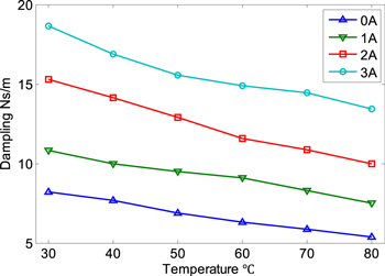
Figure 13. Damping of the MRE isolator versus temperature with different currents.
Download figure:
Standard image High-resolution imageTable 3. Stiffness (N m−1) of the MRE isolator with various currents and temperatures.
| Currents (A) | |||||
|---|---|---|---|---|---|
| Temperature (°C) | 0 | 1 | 2 | 3 | Increase (%) |
| 30 | 5363.57 | 6857.74 | 9596.74 | 12109.75 | 125.78 |
| 40 | 5219.91 | 6551.66 | 9096.14 | 11655.45 | 123.29 |
| 50 | 4999.74 | 6294.97 | 8575.84 | 10802.72 | 116.07 |
| 60 | 4781.89 | 5807.72 | 7763.81 | 10268.03 | 114.73 |
| 70 | 4644.11 | 5528.19 | 7455.54 | 9762.53 | 110.21 |
| 80 | 4399.43 | 5210.80 | 7136.11 | 8910.60 | 102.54 |
| Attenuation(30–80 °C) | 17.98% | 24.02% | 25.64% | 26.42% | |
Table 4. Damping (N s m−1) of the MRE isolator with various currents and temperatures.
| Currents (A) | |||||
|---|---|---|---|---|---|
| Temperature (°C) | 0 | 1 | 2 | 3 | Increase (%) |
| 30 | 8.213 | 10.798 | 15.270 | 18.660 | 127.20 |
| 40 | 7.663 | 9.959 | 14.120 | 16.902 | 120.57 |
| 50 | 6.860 | 9.481 | 12.913 | 15.566 | 126.91 |
| 60 | 6.288 | 9.107 | 11.589 | 14.889 | 136.78 |
| 70 | 5.879 | 8.317 | 10.868 | 14.448 | 145.76 |
| 80 | 5.375 | 7.483 | 9.999 | 13.443 | 150.10 |
| Attenuation(30–80 °C) | 34.55% | 30.70% | 34.52% | 27.96% | |
3.3. Temperature repeated experiment
The increase of temperature changes the properties of the MRE's matrix, so that the stiffness and the damping are reduced. Whether the initial characteristics of the MRE isolator are changed over a long time at high temperature will directly affect its stability and controllability. With this in mind, a temperature repeated experiment at room temperature (26 °C) after working at high temperature is undertaken. The experimental system is shown in figure 7 and the MRE isolator is supplied 3 A current for 145 min until the internal temperature rises to 85 °C before each sweeping-frequency test. When the temperature is reduced to room temperature, the sine sweeping-frequency vibration experiment is carried out, whose measuring conditions are described in section 3.2. Five groups of tests are accomplished under the same test method and the interval between each test is 24 h. The results are presented from figures 14–17.
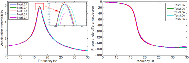
Figure 14. Magnitude-frequency and phase-frequency curves with current of 0 A.
Download figure:
Standard image High-resolution image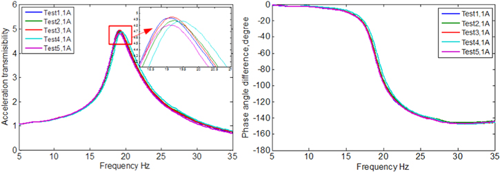
Figure 15. Magnitude-frequency and phase-frequency curves with current of 1 A.
Download figure:
Standard image High-resolution image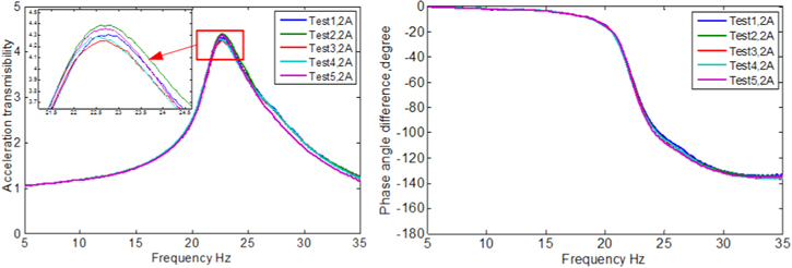
Figure 16. Magnitude-frequency and phase-frequency curves with current of 2 A.
Download figure:
Standard image High-resolution image
Figure 17. Magnitude-frequency and phase-frequency curves with current of 3 A.
Download figure:
Standard image High-resolution imageThe results show that the magnitude-frequency curves and the phase-frequency curves of transmissibility are basically the same at the same current. All test data listed in table 5 show that under the same current, the five groups of results are slightly in disagreement, with the maximum RMSE of 0.198 Hz, and there is no regular pattern between the data. Consequently, the transmissibility curves of the MRE isolator are basically consistent at room temperature after the repeated test. This means that high temperature only makes the matrix of the MRE become softer, and does not cause damage to the MRE. When the temperature is reduced to room temperature, the MRE restores to its original performance. As a result, good temperature repeatability of the MRE isolator has been attested, which is crucial for the stability and controllability of the isolator.
Table 5. Resonant frequency (Hz) of the MRE isolator with five groups of tests.
| Currents (A) | Test1 | Test2 | Test3 | Test4 | Test5 | Average | RMSE |
|---|---|---|---|---|---|---|---|
| 0 | 17.02 | 17.00 | 17.00 | 17.14 | 17.03 | 17.04 | 0.052 |
| 1 | 19.06 | 19.22 | 19.17 | 19.44 | 19.08 | 19.19 | 0.136 |
| 2 | 22.72 | 22.69 | 22.70 | 22.56 | 22.69 | 22.67 | 0.057 |
| 3 | 26.06 | 26.00 | 25.98 | 25.59 | 25.64 | 25.85 | 0.198 |
4. Cooling measure of the MRE isolator
In the long working process, due to the increase of the internal temperature, the stiffness and damping will decrease. This feature will impact the stability and increase the difficulty of control. Thus, it is very critical to adopt appropriate measures to cool the MRE isolator. Through the analysis of the MRE isolator's structure, the heat emitted by the coil can be seen mainly to dissipate to the surrounding air via the steel sleeve of the MRE isolator. Speeding up the heat exchange between the two parts can achieve a thermal balance as soon as possible, thereby reducing the temperature. Air cooling, as an effective and economical method, is adopted in this paper, which speeds up the flow of air around the surface of the MRE isolator so as to take away more heat. Furthermore, a kind of silicon grease (Model TS-KS101, Gaoyou Hengli adhesive factory, China) is applied between the coil and the steel sleeve to improve the thermal conductivity, as presented in figure 18.
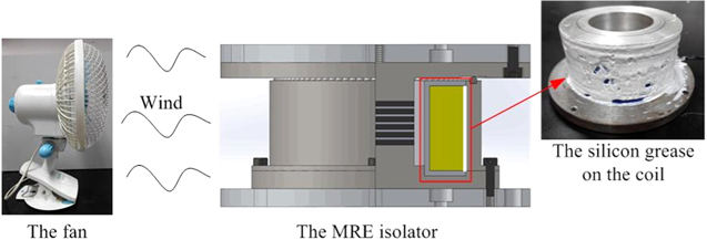
Figure 18. The cooling system of the MRE isolator.
Download figure:
Standard image High-resolution imageA temperature experiment is carried out to verify the feasibility of the method. The experimental process is the same as the section 3.1, but a fan provides the air cooling for the MRE isolator. Figure 19 shows the comparison of internal average temperature with four different cooling methods. Plainly, the temperature with air cooling and silicon grease has significant decrease and can reach a stable value of 43.5 °C more quickly, compared with 41.6 °C for no air cooling and no silicon grease. Moreover, the stable temperature with no air cooling and silicon grease is 81.1 °C and drops to 46.9 °C with air cooling and no silicon grease. It is obvious that air cooling is more useful to reduce the temperature than the silicon grease. The use of thermal grease is to improve the thermal conductivity between the coil and the steel sleeve, while air cooling is the main cooling vector for the MRE isolator. Finally, the method by using thermal grease and air cooling simultaneously can effectively reduce the influence caused by coil heating on the performance of the MRE isolator during extended working periods.

Figure 19. Comparison of internal average temperature under different cooling methods.
Download figure:
Standard image High-resolution image
5. Conclusions
A laminated MRE isolator is studied with respect to heating phenomena and the effect of temperature on its characteristics. The internal average temperature of the MRE isolator has an obvious rise with continuous operation, 26.6 °C for 0 min and 85.1 °C for 145 min, an increase of 219.92%. In addition, the temperature sweeping-frequency test shows that the resonant frequency of the MRE isolator is decreased by 13.85% linearly, while the internal temperature is increased from 30 °C to 80 °C, and the relationship between the resonant frequency, the temperature and the excitation current is accurately described by an equation. Due to the significant effect of the temperature on the characteristics of the MRE isolator, a method using silicon grease and air cooling simultaneously is proposed to reduce the temperature by 41.6 °C during the long working period, which can effectively improve the stability of the MRE isolator. Finally, based on the above research the thermal effects on the MRE isolator are further understood, which improves the feasibility of its use in engineering applications.
Acknowledgments
This research is funded by Chongqing Research Program of Basic Research and Frontier Technology (Grant No. cstc2015jcyBX0069), the Fundamental Research Funds for the Central Universities (Grant No. CDJXY120004) and the Natural Science Foundation of Chongqing (grant NO. cstc2015jcyjA0848). The authors are grateful for their supports.