

Abstract
This paper proposes a new type of magnetorheological elastomer (MRE) using rubber from waste tires and describes its performance characteristics. In this work, scrap tires were utilized as a primary matrix for the MRE without incorporation of virgin elastomers. The synthesis of the scrap tire based MRE adopted a high-temperature high-pressure sintering technique to achieve the reclaiming of vulcanized rubber. The material properties of the MRE samples were investigated through physical and viscoelastic examinations. The physical tests confirmed several material characteristics—microstructure, magnetic, and thermal properties–while the viscoelastic examination was conducted with a laboratory-made dynamic compression apparatus. It was observed from the viscoelastic examination that the proposed MRE has magnetic-field-dependent properties of the storage modulus, loss modulus, and loss tangent at different excitation frequencies and strain amplitudes. Specifically, the synthesized MRE showed a high zero field modulus, a reasonable MR effect under maximum applied current, and remarkable damping properties.
Export citation and abstract BibTeX RIS
1. Introduction
For many years, researchers have been actively seeking a means of rubber reclamation due to the growing amount of rubber waste, particularly from scrap tires [1]. Scrap tire rubber is considered to be harmful waste due to its poor decomposition resulting in serious deterioration of water, land, and air quality. Many strategies have been developed for tire rubber recycling, such as land fill, material and energy recovery, and reuse for other functional items, such as virgin rubber fillers, concrete and asphalt mixtures, as well as composite materials [2]. However, since the common rubber recycling process only uses the scrap rubber as a supplementary material, the value of the scrap rubber is very low and it is often unattractive for recycling. The value of the scrap tire rubber would be higher if it could be involved not just in the synthesis of conventional rubber mixtures, but also in the fabrication process of more valuable materials such as smart composites.
Magnetorheological elastomers (MREs), as a smart composite material, have taken a prominent position in semi-active damping devices such as automotive suspension, rotating machine mounting, and seismic dampers, due to their responsiveness and tunability properties to the magnetic fields [3, 4]. This smart composite consists of a matrix, additive, and magnetizable particles. The matrix usually comes from saturated elastomers (silicone), unsaturated rubber (natural and synthetic rubber), and thermoset or thermoplastic elastomers (polyurethane). The magnetizable particles are commonly carbonyl iron particles or other iron oxides. However, to the authors' knowledge, in the last two decades researchers have only examined the fabrication process of MREs using a virgin rubber matrix, while waste rubber processing for the MRE matrix has not yet been reported.
Semi-active devices, which incorporate MREs as the controllable material, are expected to be functionalized in multi-directional deformation. Therefore, the viscoelastic properties of all modes should be explored to establish the MR effect relationship in different types of loadings, i.e. both shear and normal. Recently, although investigation of the shear mode has been widely conducted, the compression method of MREs has received less attention [5, 6]. The stress–strain response in the static compression load provides a Young's modulus that is dependent on the magnetic field. The static compression test was first conducted by Farshad and Benine [7]. In this research, a silicone rubber based MRE was statically loaded to a certain strain amplitude revealing the Young's modulus. Other similar methods have been reported for different types of MREs, such as urethane [8], different shaped MREs [9], and urethane foam based MREs [10, 11]. Other static compression effects of MRE have been studied with respect to various attractive properties, e.g. electrical conductivity, which is dependent on the magnetic field [12, 13]. The effect on the compression rate and pre-compression normal force have been reported by Liao et al [14, 15]. Although the static compression test has shown the remarkable properties of MREs, it is not sufficient for exploring their rheological properties.
The dynamic compression test has been widely used for investigating the viscoelastic properties of elastomers. However, the dynamic compression of MREs has received less attention compared to static compression [5, 6, 16, 17]. Kallio et al [5] tested isotropic and anisotropic silicone based MREs to observe the stiffness under different magnetic field strengths and found that the maximum adjustment of the achievable spring constant was 10%. Li and Sun [6] investigated the viscoelastic properties of isotropic and anisotropic silicone based MREs using compression and a shear method in swept frequency and strain. In 2009, Koo et al [16] performed a dynamic compression test to develop a neural network based phenomenological model of isotropic silicone based MREs based on the force–displacement relationship. A similar testing method was used by Song et al [17] to investigate the viscoelastic properties of MREs influenced by the filler's shape factor, i.e. spherical and nanowire ferrous powder. Since the dynamic compression in these four studies is similar in the selected matrix, i.e. silicon rubber, it can be assumed that there are no major differences in the fabrication technique of the MREs. However, these works did not consider the development of a magnetic field apparatus for rheological testing, which is essential for estimating the value of flux density across the MRE during a rheological test.
The main technical contributions of this work are summarized as follows: (1) fabrication of a new MRE using ground tire rubber and (2) material characterizations via a step-by-step examination. In this work, fully vulcanized scrap tire rubber is introduced as the new matrix for the MRE. The successful processing of the scrap tire rubber is undertaken using a high-temperature high-pressure (HTHP) sintering method which converts the inert scrap tires into recycled rubber [18]. The HTHP is a waste rubber reclamation process that is conducted by applying simultaneous high temperature (between 200 °C and 240 °C) and high pressure compaction (above 20 MPa) on the ground tire rubber in a mold for a specific time. The process does not involve the twin screw extruder that operates through shearing the waste rubber at a temperature of ±180 °C. The fabrication method of the MRE using this technique is considered to be a new approach since virgin elastomer based MREs are processed in different ways. After making several samples, physical characterization of the MREs was undertaken to explore their microstructure and magnetic properties, together with thermal analysis. A detailed explanation of the development of the magnetic field source was also undertaken to predict the flux distribution within the test specimens. Validation of the electromagnetic device was also performed by comparing the simulation results with the measurements recorded in the experiment. Finally, the rheological properties of the waste rubber based MRE were investigated, focusing on the MR effect that is an inherent property of smart materials.
2. Materials and preparation
2.1. Raw materials
The matrix materials originated from scrap tire rubber, while the magnetizable particles were derived from ferrite block materials. The scrap tires purchased from a company (PT; Bengawan Sumber Baru, Indonesia) were in powder form and of undefined size. The source of scrap tire was purely from waste tire rubber and no contaminant from other kinds of rubber waste was present. The scrap tire rubber was separated from all metals and fabrics. The rubber powder of larger size was then shredded in the laboratory using a 60-mesh rubber granulator to achieve uniformity of powder size. The chemical properties of the crumb rubber given by the manufacturer were as follows [18]: acetone extract 7%, ash content 5.4%, carbon black 32.9%, and hydrocarbon rubber 54.6%. The additives used in this study were latex solution 15% (10 phr), sulfur (2 phr), zinc oxide (5 phr), and stearic acid (1.5 phr).
The magnetizable powder was synthesized using a high energy ball mill. The ferrite block (obtained from CV Oriental Electronic, Indonesia) was crushed using a hydraulic press until the powders passed the 60-mesh size. The screened powder was then milled using a custom-made high energy ball mill with an angular velocity of 500 rpm. The mass ratio of powder to ball mill was 1:10. In this work, 50 g powder was ground using a 500 g hardened steel ball in 50 ml ethanol. The ground powder was then dried at 70 °C for an hour. The ground powder was examined to determine its physic properties, and the results were identified as magnetite particle (Fe3O4) based on their diffraction and transmittance patterns.
2.2. Fabrication
The fabrication of the MRE specimens consisted of two major steps, namely mixing and reclaiming. Since the expected type of MRE was isotropic, electromagnetic treatment was absent during the reclamation process. In this work, four variations of MRE samples were synthesized i.e. 10, 20, 30, and 40 wt% of filler fractions. A laboratory-made mixer was utilized for mixing the crumb rubber, additive, and magnetite powder at 250 rpm. A homogenous mixture was quickly achieved since all the raw materials were in powder form. The mixing was firstly conducted for 100 phr of crumb rubber with 2 phr sulfur, 5 phr zinc oxide, and 1.5 phr stearic acid using a mechanical mixer. The first mixing was undertaken for 15–30 min. When mixing the matrix materials, 10 phr latex solution 15% was added and mixed for 15 min. Since the total mass of the molded materials was set to 10 grams each, the weight comparisons of rubber mixture and magnetite powder were 9:1, 8:2, 7:3, and 6:4 for 10 wt%, 20 wt%, 30 wt%, and 40 wt% of MREs, respectively. By taking the appropriate mass of rubber mixture and magnetite powder, the matrix and fillers were mixed homogeneously. The final step was placing the mixture in a HTHP mold with a diameter of 30 mm.
The mold was then mounted in the HTHP device, as shown in figure 1. The HTHP device was constructed from several parts; a hydraulic unit, a heater controller, and a heater element. The sintering of the MRE specimens was performed by first applying a hydraulic pressure of 25 MPa to the molding followed by heating at 200 °C. The maximum heating rate achieved by the controller was about 10 °C/min. During sample preparation, the initial temperature was about 25 °C– 27 °C (room temperature) transiently increasing until 200 °C for 17–20 min. After achieving a steady state temperature, the controller continuously supplied electric current to the heater elements based on the temperature set point. The HTHP process took an hour. The hot mold was then allowed to cool until it reached the ambient temperature.
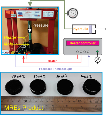
Figure 1. The HTHP fabrication device and the resulting MRE specimens.
Download figure:
Standard image High-resolution imageFigure 1 also depicts the fabricated MRE samples in coin shape. The size of the specimen, especially the thickness (measured with a displacement sensor), depends on the composition of the mixture since the sintered mixtures had the same mass. A higher magnetite content produced a lower sample thickness. The density of the specimens was measured using a density meter for further identification of the equivalent volume fraction. The densities and filler fraction also reveal a linear relationship. The assessment of volume fraction was derived using equation (1) [19];

where  is the density of MREs;
  is the density of pure reclaimed rubber, and
  is the density of magnetite powder. The base densities for the pure reclaimed rubber and magnetite powder were 1.107 g cm−3 and 5.27 g cm−3, respectively.
3. Experimental details and apparatus
3.1. Microstructural observation
Microstructural observation was undertaken to provide the information concerning the magnetite shape, size, and dispersion within the matrix. Scanning electron microscopy (SEM; FEI-Inspect) was utilized to capture the magnetite powder's distribution within the matrix. The device was operated at an accelerating voltage of 10 kV (magnetite powder examination) and 5 kV (microstructure of the MRE). In SEM observation, the MRE samples were shattered to expose their interior. The observed surfaces were coated with a thin layer of gold. The particle size distribution (PSD) of the magnetite was measured using Shimadzu Particle Size Analyzer 2300 (Kyoto, Japan).
3.2. Magnetic measurement
The magnetic characterization was carried out using Lake Shore vibrating sample magnetometry. The tests were conducted before and after MRE fabrication. The initial evaluation was used to characterize the laboratory-prepared magnetite powders. This test is beneficial for determining the relative magnetic permeability of the pure magnetite particles. Meanwhile, the post-fabrication test was undertaken to evaluate the magnetic properties of the MRE samples. The experimental curves were measured at ambient temperature after applying a maximum field intensity of 1 T. The magnetic properties of the laboratory-prepared magnetite as well as MRE samples were measured at room temperature from −1–1 T.
3.3. Thermal characterization
The importance of thermal analysis for the MRE is mainly associated with the stability and degradation of the elastomers. Differential scanning calorimetry (DSC) was utilized to reveal the thermal properties of the waste based MREs. Examination is necessary since the issue for reclaimed rubber is its thermal properties and stability during operation under extreme condition. The DSC test covered the pure reclaimed waste rubber and the MRE in various weight fractions for assessment of the thermal glass transition temperature. The Shimadzu DSC-60A utilized in this study was adaptable to the step-scan method. The method was conducted in combination with power compensation. The technique dissociated the reversible and irreversible reactions by employing a sequence of short interval cooling from ambient temperature to −100 °C using liquid nitrogen, which was then heated to 0 °C. The convection cooling rate was set 10 °C/min.
3.4. The electromagnetic device
It is commonly known that the compression behavior of elastomeric materials is strongly influenced by the interface condition between the pressure plate and the specimen [20]. According to this situation, the rubber compression test is divided into three states—bonded, free friction, and single fixed end. The non-linear dynamics of compressed rubber exhibits a different behavior according to the compression state, in which the natural behavior of the compressed elastomer can be revealed by implementing the bonded state. The specimen is bonded permanently to the compression plate at the surface tips. In this situation, the compressed rubber shows the highest achievable modulus or stiffness. The dynamic compression of the MREs performed in this study employed the bonded state.
The dynamic compression test of the MREs must be conducted using a permanent magnet [16] or electromagnetic device [5]. The flux density of the permanent magnet can be controlled by adjusting the distance between two adjacent magnets. Although utilizing a permanent magnet seems simple, the span of the flux density capability is narrower than that for an electromagnetic device. The other disadvantage is that the flux density drops as the distance between the permanent magnets increases [16]. This research utilized an electromagnetic device with functions for generating high flux density as well as compression. Figure 2 depicts the cross sectional view and the fabricated electromagnetic unit.
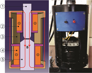
Figure 2. Electromagnetic unit (1: upper jaw; 2: upper coil; 3: cover; 4: lower coil; and 5: lower jaw).
Download figure:
Standard image High-resolution imageIt is important to note that the electromagnet utilized in the rheological test should be capable of producing a higher flux density within the test area than the magnetization saturation (Ms) of the MRE samples. In addition, the magnetic flux generated within the test area of the electromagnetic device must be easily monitored by the operator. Moreover, the coils should be in direct contact with the free air for heat discharge when the electric current is applied. Based on the mentioned requirements, the design of the electromagnetic device was developed as depicted in figure 2. The electromagnetic device mainly consists of two coil–bobbin sets, a steel cover, and center jaws. One of the center jaws (the lower jaw) is fixed to the load cell while the other moves with the hydraulic actuator. The movement of the upper jaw should be free from the static parts with no friction, as friction will affect the reading of the load sensor.
The electromagnetic parts, such as the number of wire turns, were first determined through magnetic circuit analysis. The present electromagnetic design was capable of generating more than 500 mT in the test area without MREs with a gap thickness of 12 mm. According to the provided bobbin space, each coil was calculated as having 1250 turns, a wire diameter of 1 mm, wire resistance of 12.6 ohms, and a maximum current of 5 A. The jaws and cover materials were AISI 4140; for the magnetic properties for the software input see Shahreza et al [21].
3.5. Dynamic test method
The simplified system of the compression test is illustrated in figure 3. The compression mode of the MREs is identical to the lumped spring elements consisting of a cylindrical MRE subjected to a cyclic compression force for off-state and on-state (external magnetic field application). A Shimadzu ServoPulser L Series (Shimadzu, Kyoto, Japan) was used to perform the compression test with a maximum force range of ±20 kN. The fatigue dynamic machine has a functional excitation frequency range of 0.1 up to 50 Hz, depending on the excitation amplitude (10–0.9 mm). The Shimadzu Servo Controller 4830 was equipped with user interface software that could produce the force and displacement data in the time domain to obtain force–displacement curves. The stress–strain relationship was also determined by the software according to the dimensions of the MRE.
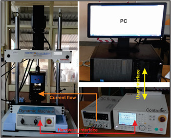
Figure 3. Diagram of the dynamic compression test.
Download figure:
Standard image High-resolution imageThe dynamic compression tests were performed at various excitation frequencies of 1, 3, 5, 7, 10, 13, and 16 Hz with a constant strain amplitude of 10%. Meanwhile, various swept strain amplitudes were used—1, 3, 5, 7 and 10%—under a 1 Hz excitation frequency. The strain amplitude was controlled according to the cyclic equation of  where
where  is strain amplitude and
  is the excitation frequency in rad/s. In practice, the dynamic machine regulates the excitation frequency
  in Hz. The MRE specimen was subjected to harmonic loading that fluctuates about the mean level (half of the strain amplitude). During the compression test, the current from the DC power supply was regulated from 0–5 A. The temperature of the electromagnetic core, which was in direct contact with the sample, was monitored as the current drained to the coil. The temperature was kept below 60 °C to maintain the condition of the specimen.
The rheological properties of various elastomers have been studied by applying cyclic stress or strain. This technique applies to all linear viscoelastic materials. When the MRE sample is subjected to oscillating strain, the stress also develops an indirect response in the time domain as  The symbol
  represents the phase shift between the stress and strain. The phase shift indicates the specific characteristic of a viscoelastic material. The associated quantity to determine the property is
  or loss tangent/loss tangent. The key property of the MRE can be calculated using the simple relationship given in equation (2):

where, E* is the complex modulus. The E* and  are key viscoelastic characteristics of the MRE [22]. The complex modulus consists of real and imaginary parts expressed as follows (equation (3)):

where,  is the storage modulus and
  is the loss modulus. These two values are suitable for explaining the viscoelastic material properties of the MREs. The quantity of storage modulus and loss modulus can be determined from the relationship in the following equations.


The relative MR effect can be further determined by

4. Results and discussion
In this section, all the experimental results are presented along with discussion of the physical properties of the MREs including their microstructure, magnetic properties, and thermal properties. The electromagnetic device magnetostatic simulation and experimental validation are also explained as well as the viscoelasticity in compression mode. Some parameters are varied, including filler concentration, magnetic flux, excitation frequency, and strain amplitude. The analysis on viscoelastic properties is to identify mechanical characteristics, such as the storage modulus, loss modulus, and loss tangent of the waste rubber based MRE by applying different magnetic field intensities.
4.1. Microstructure analysis
The morphology and size distribution of the magnetite powder are shown in figure 4. The particles have a narrow distribution with a size of 0.5–25 μm according to the scale and irregular shape. Based on the particle size analysis test, the PSD is measured as d10 = 6.517 μm, d50 = 16.919 μm, and d90 = 44.142 μm. A photograph of the MRE interior containing magnetite powder with a weight fraction of 40 wt% is also shown in figure 4. Well-dispersed magnetite powder was found within the MRE matrix. It can be seen that the magnetite powder penetrates deep into the matrix without any voids. The absence of voids is caused by the high pressure applied during the HTHP process. The phenomenon also implies that no oxidation occurred within the reclaimed rubber.

Figure 4. Microstructural properties of the sliced MRE as well as particle shape and size.
Download figure:
Standard image High-resolution imageThe average size of the magnetite is finer than the tire rubber powder. Therefore, the mechanical mixing allows the magnetite to penetrate easily into the tire rubber powders. In the early stages, the homogenous mixture of magnetite and other raw materials could easily be observed visually. During the HTHP process, the magnetite could not move with ease since it was restricted by the high pressure applied. As a result, good dispersion was obtained as shown in figure 4. Well-dispersed particles is a primary requirement for the consistent performance of isotropic MREs. The responsiveness of MREs to the external magnetic flux is also influenced by the dispersion of magnetic particles [19, 23, 24]. A good distribution will ensure the magnetic flux flows uniformly through the MREs. The dispersion of particles can be shown by direct evidence from SEM. Similar phenomena were also found in the samples with a lower weight fraction of magnetite powder.
4.2. Magnetic properties
The hysteresis curves of the MREs with various weight fractions of magnetite are depicted in figure 5. The figure displays the hysteresis loops for different MRE samples, i.e. 10, 20, 30, and 40 wt%. Table 1 shows the corresponding magnetic properties of the MREs including their retentivity, magnetization, and coercivity. The thin loops of the hysteresis curves show that the MREs are magnetically soft the ambient temperature. The coercivity (Hc) of all the samples supports the soft magnetic property in which the values are lower than 90 Oe (7161.972 A m−1) [25]. The quantity of the coercivity is reduced with the alteration of the filler content. Meanwhile, the magnetization (Ms) and retentivity (Mr) act on the reverse values. The measured properties are parallel to the studies on magnetite–thermoplastic natural rubber nanocomposites reported by Kong et al [26] and polymeric composite based barium ferrite reported by Ahmed et al [27]. It could be inferred from the higher values of the coercivity that it would be more difficult to demagnetize the MRE at a lower filler content. The increase in magnetization and retentivity is also in-line with the quantity of magnetic susceptibility.

Figure 5. Magnetization curves of various MREs.
Download figure:
Standard image High-resolution imageTable 1. Magnetic properties of the MREs with different filler fractions.
| Sample | Retentivity Mr (emu g–1) | Magnetization, Ms (emu –g) | Coercivity, Hc (A m–1) |
|---|---|---|---|
| 10 wt% MREs | 0.221 | 7.216 | 3435.54 |
| 20 wt% MREs | 0.873 | 14.185 | 3355.30 |
| 30 wt% MREs | 1.326 | 20.723 | 3339.09 |
| 40 wt% MREs | 1.859 | 27.709 | 3265.65 |
| Pure magnetite | 4.7 | 85.775 | 2799.69 |
4.3. Thermal analysis
The influence of the filler particle on the thermal properties of the reclaimed rubber was investigated. DSC analysis was conducted to examine the characteristic temperatures of phase transformation in this reclaimed rubber matrix. Figure 6 shows the DSC curves of the MRE samples for various weight fractions of magnetite compared with the pure reclaimed scrap tire rubber. The reclaimed rubber was synthesized using the same procedure as that of the MRE samples. All the plotted curves exhibit the same pattern in which the compatibility of the matrix and magnetizable particles is exhibited in the single enthalpy exothermic phase. The phase transition (glassy state to rubbery state) shows an endothermic reaction at an interval of −65°C to −55 °C. The thermal glass transition temperatures (Tg) were obtained using analytical software, and the Tg value ranges were −0.6 °C ± 0.5 °C for all measured samples, independent of the filler fraction. The calculated Tg also confirm that the value is equivalent to the thermal properties of vulcanized virgin styrene butadiene rubber–natural rubber studied by Kim et al [28]. The insertion of magnetite powder does not have a substantial effect on the thermal glass transition temperature. There is no evidence of the influence of the magnetite powder fraction on the rubber curing during the reclamation process. Magnetite powder dispersed within the rubber matrix has a better thermal conductivity than the matrix itself. Moreover, in composite materials, the thermal conductivity is strongly influenced by the fraction of thermally conductive materials. The better thermal conductivity and higher weight fraction of the magnetizable particles is also indicated by the up-shift in the curves for each sample. A higher fraction of particles can cause an increase in the ability of heat flow across the samples. Consequently, MREs with a larger weight fraction commonly have better thermal conductivity.
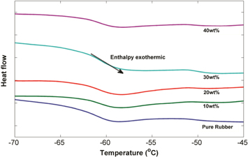
Figure 6. DSC curve of pure rubber and MRE samples.
Download figure:
Standard image High-resolution image4.4. Electromagnetic validation
The performance of the electromagnetic apparatus was evaluated through simulation and experimental activities. Figure 7(a) shows the magnetic flux distribution within the electromagnetic device obtained from magnetostatic simulation. The flux lines passing through the steel jaws, cover, and air gaps with slight leakage outside the instrument form a closed loop magnetic circuit. The flux lines are directed in a parallel direction to the movement of the upper jaw because the current flows perpendicular to the jaw. The concentration of magnetic flux along the jaws confirms the strength of flux density within the chamber test. The color distribution in the air gap, as shown in the zoomed picture, indicates the uniformity of the flux density, despite the flux fringing around the air gap. The magnetostatic simulation plotted in figure 7(a) resulted from a 1 A current applied in each coil. The simulation is performed in various clearances of the test area and currents. The air gap distances are set to be 4, 8, and 12 mm. The currents are varied from 0–5 A with an interval of 0.25 A. The average flux at the center of the test is presented in flux density as a function of the applied current. Figure 7(b) shows the increase of the flux density at various distances and currents. The patterns show that the increase in gap causes a marked decrease in the flux density. The maximum flux densities with a 5 A current are 0.83, 1.14, and 1.77 T for 12, 8, and 4 mm clearances, respectively. The maximum achievable flux density for the 12 mm gap exceeds the design expectation. Justification of the magnetostatic simulation results is conducted by comparing the simulation results with the measured flux density across the test area after the prototype was developed. The magnetic flux was measured using a Gaussmeter GM08 (Hirst Magnetic Instruments, UK) using the same jaw distance as the simulation. The current was regulated by a power supply (TTi CPX 4000, a maximum current of 20 A DC) of 0–5 A. Figure 7(b) depicts a comparison between the simulation and the measurement results. Since the differences between the quantities are still acceptable, the simulation model can be considered to be valid and, hence, can be used for further reference.
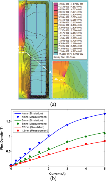
Figure 7. (a) Finite element method magnetics (FEMM) simulation without MRE samples and (b) results in validation for various gaps and currents.
Download figure:
Standard image High-resolution imageThe MRE samples vary in thickness and have different magnetic properties. The previous simulation is only valid for the condition without the MRE sample, which means the test area has no sample. The following addresses the magnetostatic simulation when the MRE is placed in the test area. The importance of this simulation is mainly due to the absence of a sensor, which can measure the flux density inside the materials. Based on the limitation, most of the previous works used a gaussmeter placed near the MREs being tested. The magnetic flux reading through the aforementioned procedure is less accurate since the gaussmeter probe does not measure the exact flux density within the MRE. Therefore, the proposed magnetostatic simulation helps the prediction of the flux density passing through the MRE samples. Next, the air gap in the magnetostatic model is replaced by the MRE, including the magnetic properties and dimension of the simulation setting parameters. The magnetic properties are derived from the measurement data. The magnetic field distribution depicted in figure 8(a) shows the simulation result for the MRE 40 wt% (10.55 mm thickness) in a 1 A current. The figure shows a higher density of the magnetic flux across the MREs compared to the air gap, and also uniformity in both the lateral and axial directions. Since the jaws interconnected to the MREs have good magnetic permeability, the magnetic flux flows more easily within the MRE. Figure 8(b) summarizes the simulation results for all specimens. The input parameters are the variation in thickness depending on the type of MRE and current applied to the coils. The current is varied from 0–5 A. The flux density values are also logged from the average value across the sample. From the figure, it can be inferred that the flux density escalates according to the increase in the current applied as well as the augmentation of the particle weight fraction. The highest flux density achieved by the MRE 10 wt% is about 1000 mT at 5 A applied current. The value is sufficient for magnetizing the MRE samples. Figure 8(b) can also be used as a reference for equivalency between the electric current and flux density since the upcoming viscoelastic behaviors are provided in the electric current domain.

Figure 8. (a) Field distribution across the MRE samples and (b) quantity of flux density in various MRE types and applied current.
Download figure:
Standard image High-resolution image4.5. Viscoelastic properties
As mentioned above, the base matrix used in the MREs originated from scrap tire rubber. It is commonly known that tire rubber has a high content of carbon black. The insertion of carbon black in virgin rubber during tire production strongly influences the modulus characteristics. The analytical relationship between the modulus of virgin rubber and carbon black filled rubber has been extensively studied previously. The theoretical frame of particle filled rubber has been established by Guth [29] based on the theory of viscosity. The modulus of ordinary particle filled rubber is stated as follows:

where, E* is the filled rubber modulus, Ei is the initial modulus, and ϕ is the volume fraction of filler. The equation is also applicable to the other constants, such as shear modulus (G) and stiffness modulus (K), since E, G, and K have a linear relationship. Figure 9 shows the modulus of pure reclaimed rubber and various types of MRE. The modulus of unfilled rubber is used as the initial modulus value Ei for Guth's model prediction. The measured modulus of the MREs is then superimposed with the prediction result. The modulus of various weight fractions follows the prediction with acceptable deviation. The viscoelastic behavior of the waste rubber based MREs is introduced in the form of the dynamic stress–strain relationship. The stress–strain data are obtained in the time domain and further examined to determine the other parameters. All the samples are tested and configured to monitor the stress–strain relation under the magnetic field. Due to the extensive data logged in various treatments, this section only shows the stress–strain characteristics of a particular MRE.

Figure 9. Off-state complex modulus of the MREs in various volume fractions.
Download figure:
Standard image High-resolution imageFigure 10(a) shows the stress–strain curves of MRE 40 wt% with various applied currents under cyclic loading. The testing is conducted with an excitation frequency of 1 Hz and 10% strain amplitude. The stress–strain curves were derived from the force–displacement data. Therefore, the hysteresis trends must be identical. The MRE stiffness can be determined from the force–displacement signals. However, the primary objective of this study is to explore the field-dependent modulus. From the figure, it can be inferred that the near-elliptical loops change according to the current increase. The gradient of the major axis varies with the magnetic flux. This also confirms the alteration of the MRE stiffness. The areas covered by the loading and unloading curve also change according to the increase in the current. This indicates that the damping capacity also varies according to the different magnetic fields. The maximum stress at 10% strain amplitude increases gradually as the current is applied from 0 to 3 A. However, the stress quantity changes slightly from 3 to 5 A. This occurrence indicates that the stress does not increase when a higher magnetic flux is applied to the MRE. Figures 10(b) and (c), respectively, depict the hysteresis curve for various frequencies and strain amplitudes with a constant current. The different testing frequencies shown in the graph are performed under a constant strain amplitude of 10% and a 1 A current. The stress increases steadily with a relatively similar difference. There is no saturation of the stress caused by the higher excitation frequency. The continuous rise in peak frequency causes a change in the area of the near-elliptical loops. This fact physically means that the stiffness and damping properties are also altered. It is also observed that the damping capacity of the MRE can change the compression–relaxation response, namely the phase lag. Figure 10(c) presents the stress–strain curves for various strain amplitudes at a constant frequency of 1 Hz, and a constant current of 1 A. When the strain amplitude is changed sequentially, the small strain amplitude actuation provides a small stress value.
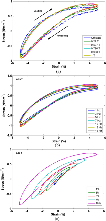
Figure 10. Hysteresis stress strain curves for 40 wt% MREs: (a) various currents, (b) various excitation frequencies, and (c) various excitation amplitudes.
Download figure:
Standard image High-resolution imageIt is commonly known that the elastomer stress–strain curve in response to cyclic loading has a symmetric, elliptical shape. Therefore, the stress–strain curves for the lower amplitude are covered by the stress–strain curves at a higher strain. The situation shown in figure 10(c) is rather different to that commonly found in previous works [5, 30]. The stress–strain response for 1% amplitude seems to be symmetrical between the loading and unloading states. However, the shape of the curve becomes asymmetrical with a higher excitation strain. From the phenomena it can be inferred that the higher compression strain in the axial direction causes longer displacement in the internal particles. However, the internal movement, particularly in the lateral direction, is restricted by the matrix–filler bonding. Therefore, during the compression stroke, the sample seems to be suppressed in a uni-direction. The higher strain excitation might also cause relative displacement between the sample and jaw at the contact surface resulting in a loss of stress [31].
The other quantities representing the viscoelastic properties of the MREs, i.e. field-dependent modulus, loss tangent, and MR effect, are determined from the stress–strain relationship. Figures 11(a) and (b), respectively, show the storage modulus and loss modulus for all samples under different current intensities. Both the storage modulus and loss modulus have the same trends. Taking the MRE 40 wt% data, the storage modulus rises according to the increase in flux density, which is represented by the applied current. The increase is limited to a particular current, and then it tends to level off. The same situation occurs for the loss modulus of the sample. However, the lower fraction of MRE shows a slight increase in both the storage modulus and loss modulus. A relatively small difference between the off-state and maximum applied current can be influenced by certain factors, such as the magnetite powder content, the powder dispersion (random or aligned), and the high initial modulus of the base matrix. The loss tangent data are presented in figure 11(c). The quantity of loss tangent for carbon black filled rubber can exceed 0.8. This quantity is usually possessed by hard rubber that has a high damping capability. The magnetic field effects on the waste rubber based MRE influence the quantity of loss tangent. The increase in magnetic field intensity makes the loss tangent grow gradually. Meanwhile, at the same flux density, the loss tangent increases with the magnetite weight fraction. The change in loss tangent means that the damping property of each sample can be controlled by regulating a proper magnetic flux density.
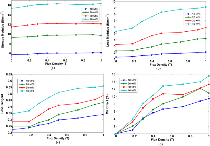
Figure 11. Viscoelastic behaviors of various samples of 1 A, 1 Hz, and 10% amplitude: (a) storage modulus, (b) loss modulus, (c) loss tangent, and (d) MR effect.
Download figure:
Standard image High-resolution imageThe MR effect is always the reference for the performance assessment of MREs. The alteration in the ability of intrinsic properties can be directly evaluated from the value of the MR effect. From this parameter, the reader can imagine how far the MRE is responding to the appearance of the magnetic field. Figure 11(d) displays the MR effect of all samples for the various applied currents. The presented data are calculated from the storage modulus values. The highest MR effect is achieved by the MRE 40 wt%, which is about 15%, while the lowest one is about 9%. The MR effect of isotropic MREs is usually small. Therefore, most researchers recommend the anisotropic type [32]. The viscoelastic properties of waste based MREs are also investigated in terms of swept frequency and strain amplitude. The modulus and loss tangent dependence on the magnetic field are presented in logarithmic scale. The change in properties between a free magnetic field and under a magnetic field is shown by the sample test at 0 and 5 A. Figure 12(a) demonstrates the rheological properties that cover frequency ranges from 1–16 Hz. The storage moduli of all MRE types increase gradually with the increase in frequency. The consistent increase is also found in the magnetic field variation. The growth of the storage modulus is logarithmically linear. The prediction for the storage modulus of a particular specimen at various frequencies (within the test span) can be seen from the graph. This is the benefit of using a logarithmic scale [33].

Figure 12. Viscoelastic behavior in swept frequency at the off-state and 1 T, 10% strain: (a) storage modulus, (b) loss modulus, and (c) loss tangent.
Download figure:
Standard image High-resolution imageIn contrast, the loss modulus and loss tangent show a different trend to the storage modulus in the frequency domain. As can be seen in figures 12(b) and (c), both the loss modulus and loss tangent diminish gradually until the excitation frequency reaches 13 Hz and then increase. At this frequency the storage modulus also increases followed by a reduction in value above 13 Hz. However, the values of the demagnetized condition are consistently higher than that of the non-magnetized treatment. The value of the slope for the storage modulus is lower those that of the loss modulus and loss tangent. Based on this fact, it can be inferred that the change in frequency is the dominant influence on the loss modulus and loss tangent. The dissipated energy, which strongly correlates with the loss modulus, is more prominent than the stiffness factor.
The behaviors of waste based MREs at various compression strains are depicted in figures 13(a)– (c). Figure 13(a) shows that the storage modulus drops steadily with a constant excitation frequency of 1 Hz. The decrease in storage modulus could be caused by the microstructural deformation of the specimen. The high strain in the compression mode potentially destroys the bonding between the matrix and magnetizable powder. Therefore, the stiffness of the MREs diminishes gradually as a result of microscopic bonding. The slope of the decrease is most evident in the MRE 40 wt%. The higher powder content reduces the distance between particles. Hence, the slope of the lower filler content is flatter than for the higher one. Different to the storage modulus behavior, the loss modulus and loss storage have an tendency to increase after the drop in value in the first stage strain amplitude (1%–3% amplitude). This fact can clearly be seen in figures 13(b) and (c). The off-state and on-state conditions consistently show differences as per the previous phenomena. The closer distance or smaller thickness of the MREs is accompanied by a higher magnetic field intensity, as can be conceived from the finite element magnetic simulation undertaken in this work. The current circumstances imply that the loss modulus and loss tangent strongly depend on the increase in the strain amplitude. In general, the changed in the storage modulus, loss modulus, and loss tangent under various magnetic fields, frequencies, and amplitude excitations clearly confirms the control capability of the damping characteristics of the MREs proposed in this work.

Figure 13. Viscoelastic behavior in swept strain, 0 and 5 A, 1 Hz excitation frequency: (a) storage modulus, (b) loss modulus, and (c) loss tangent.
Download figure:
Standard image High-resolution image
4.6. Remarks
A strong MR effect is commonly preferred by researchers working in the MR materials area. This is almost achieved in the elastomeric base matrix with small viscoelastic properties under zero magnetic fields, for example, a soft elastomeric matrix. Soft elastomers are easily found in miscible polymer based elastomers, such as silicone room temperature vulcanization (RTV) and polydimethylsiloxane (PDMS). Therefore, most previous works on the synthesis of MREs chose silicone RTV or another liquid based elastomer as the matrix carrier rather than synthetic or natural rubbers [4]. The low off-state property of MREs is indeed applicable to wide semi-active devices or systems. However, some applications need relatively high off-state properties; for instance, seismic bearing load [34]. The rubber bearing applied in seismic applications requires high damping and toughness for extended span utilization. According to the application, the MR effect of the MREs is somehow sacrificed [6]. Therefore, achieving a high MR effect with high mechanical properties (in zero magnetic fields) for MREs requires a major effort.
The synthesized MREs in this study are as described previously. In general, waste based MREs have a high off-state modulus. The main reason being that the raw material of the base matrix contains un-negligible carbon black. Thus, the modulus of pure reclaimed rubber is much higher than for the conventionally used matrix in MREs. Furthermore, the insertion of magnetite powder also affects the base modulus of the material. Therefore, it is understandable that the maximum achievable MR effect is only about 15%. However, this new class of MREs provides unique properties, especially in the decrease of the storage modulus in the scanned strain amplitude.
The reduction in the modulus in increasing strain is absent from the behavior of 'pure gum' rubber [35]. This phenomenon occurs when an active filler is inserted throughout the rubber; for instance, carbon black, silica, or metallic particles. The strain dependence modulus of rubber reinforced particles has been formerly investigated by Payne [35, 36]. This situation is valid for all modes—compression, shear, or tensile. The waste based MREs show the effect identified by Payne, as depicted in figure 13(a), in which their storage modulus gradually diminishes according to the increase in strain. The Payne effect can be an indicator of the bonding strength between the particles and the matrix [37].
Another interesting behavior of waste based MREs is their high-value loss tangent, as depicted in figure 11(c), in which an increase of the loss tangent occurs when the current is elevated. The loss tangent plays a significant role in viscoelastic materials, in particular for damping properties. The damping property of a regular particle reinforced elastomeric composite is naturally influenced by the filler condition. The damping mechanism of this kind of composite is attributed to certain factors, such as intrinsic damping, interparticle friction, particle–matrix interaction, and thermal dislocation, caused by the applied strain [38]. In MREs, the influencing factors include the effects of magneto-mechanical interaction. So far, the investigation of damping mechanisms within MREs is restricted to model predictions, rather than experimental results. The direct experimental investigation of the specific factors affecting the damping mechanism has not yet been reported. Thus, the portion contributed by the influencing factors to the MRE damping has not been explicitly quantified. However, most researchers state that the damping in MREs is dominantly influenced by the particle–matrix interaction.
The Payne effect and loss tangent have a strong relationship. According to the viscoelastic behavior of the waste based MREs, the microstructure change of MREs is affected by the deformation, which will cause breakage and the recovery of weak bonding. In this case, the magnetite powder and waste rubber matrix form a small structure. The reclaimed rubber interconnects the adjacent particles. Consequently, when the strain amplitude is applied to the MRE sample, the interparticle distance also changes. In the case of compression, the loading direction is parallel to the longitudinal axis of the sample. Meanwhile, the deformation of the MRE tends to be in the lateral direction. The cyclic strain leads to the particles being repeatedly restrained and returned. The microscopic movement may break the particle–matrix bond, and, hence, the small structures are destroyed. This phenomenon may cause a decrease in the storage modulus at the same time. Along with the cyclic loading and the existence of the relative microscopic movement between the magnetite particles and rubber matrix, the friction will increase, resulting in an increase in the loss tangent. According to the microstructure results, as depicted in figure 4, a major break in the particle–matrix bonding was not found. The photograph was taken from a sliced sample after testing. Thus, it is predicted that the relative movement that occurred in the synthesized MREs must be of a subtle nature, and would appear after cyclic loading and long term excitation. Furthermore, the waste rubber based MREs are believed to have a broad range of controllable damping properties that are suitable for a wide arrange of applications, such as semi-active devices, and systems, such as seismic absorbers.
However, it is acknowledged that the proposed MREs still have certain drawbacks. For example, the proposed MREs need to be further improved to have better viscoelastic properties. The potentially important issues that require exploration in future studies are the matrix–filler compatibility and the filler structure within the matrix. The compatibility of the waste rubber and magnetite can be improved through surface particle modification or an additional bonding agent, as investigated in earlier studies [39–41]. The aligning of particles within the MRE matrix is also expected to increase the MR effect. In addition, the modification of the HTHP method is another challenging problem in terms of the fabrication technique.
4.7. Reliability issues
The primary requirement for the implementation of reclaimed waste tire rubber is that the rubber should have adequate durability and life span. This requirement should also be appointed to MRE based devices, such as adaptive tunable vibration absorbers, since they are constructed of soft (elastomeric matrix) and hard materials (magnetizable powder). Most of the devices are implemented in fluctuating loads, with environmental alteration in the long term. The stability and degradation of the MREs must be the primary consideration in various different operating conditions. Thermal analyses, such as DSC, thermogravimetric analysis (TGA/DTA), dynamic mechanical-thermal analysis (DMTA), aging tests, and thermal oxidation, as well as UV oxidation, are usually conducted to investigate the performance of elastomeric materials, including MREs, to determine their response to thermal loads. Studies on the thermal analysis of MREs based on virgin elastomers can be found in some previous works [32, 42, 43, 43–47]. Since the specimens studied in this report had waste rubber as the MRE matrix, there is no report that precisely explains the stability and degradation. A broad investigation of the thermal analysis of waste rubber based MREs will be presented in a future report.
The approach for predicting the durability of the waste rubber based MREs can be based on an initial assessment of the thermal stability of the reclaimed waste rubber. The thermal analysis of reclaimed waste rubber, in particular ground tire rubber, has been explored in some previous reports. The thermal analysis of reclaimed tire rubber waste, without mixing with virgin rubber, has been investigated by some researchers [48–50]. The method for compounding crumb rubber utilizes a screw mixer at a temperature of 180 °C and an applied shear pressure of less than the pressure in the HPHT reclamation process by Morin et al [51], with additional vulcanization agents. In the work performed by De et al [48], the reclaimed tire rubber retains good tensile and hardness properties. Even with the additional concentration of TMTD, the phenomenon showed the anti-aging characteristics of the reclaimed rubber. The results confirmed that the aging characteristics of reclaimed rubber were comparable to virgin natural rubber. Formela et al [49] investigated the thermomechanical reclaiming process of waste tire rubber and concluded that the reclaiming process influenced the thermal characteristics; this relation was confirmed by the Horikx theory. Meanwhile, Shi et al [50] upheld the stability of reclaimed waste tires through DSC examination. It was reported that the thermal glass transition temperature was slightly different to that of raw natural rubber. Based on the aforementioned investigation, the reclaimed waste tire rubber has a reasonable durability near to that of virgin rubber. Accordingly, this could be used as preliminary judgment for the durability of waste tire based MREs, albeit the prediction must be scientifically proven through thermal analysis.
5. Conclusion
In this work, a new type of MRE based on waste tire rubber was fabricated and field-dependent material characterizations were undertaken under both static and dynamic conditions. In particular, this work explored the possibility of waste tire rubber as the primary matrix of MREs. The reclaimed rubber based MREs were synthesized using a proven technique, namely HTHP sintering. Some physical-chemical examinations were conducted to investigate the microstructural properties, magnetic properties, and thermal glass transition. The magnetite powder was dispersed randomly within the rubber matrix without meaningful agglomeration. The thermal glass transition temperature of the waste tire rubber based MRE was determined at −60.6 °C ± 0.5 °C, which is comparable with reclaimed waste tire rubber (without magnetite powder). The development of an electromagnetic device for compression test was performed from the magnetic circuit analysis, finite element simulation, and fabrication. The validity of the simulation results on magnetic field generation were proven by comparing with the experimental results. Based on this validated model, the flux density across the MREs was accurately predicted through the simulation. The electromagnetic device was then integrated into the fatigue dynamic machine for MRE compression tests. The produced MREs have shown their controllable properties with the appearance of a magnetic field. The effect of increasing frequency on the MREs caused a slight increase in the storage modulus and a decrease in the loss modulus and loss tangent. Meanwhile, the growth of strain amplitude caused a meaningful decrease in the storage modulus (the Payne effect) and an increase in the loss modulus and loss tangent. In addition, it was demonstrated that the reclaimed rubber based MREs possess a wider tunable property of damping capacities than for the stiffness properties. Consequently, this class of MREs is an excellent candidate for applications that require controllable high damping capability, such as seismic shock absorbers or for the automotive industry. Future works concerning the utilization of waste tire rubber, such as for the MRE matrix, should concentrate on the reliability and durability issue, which is normally investigated through thermal analysis, as well as the aging effect in terms of its rheological properties.
Acknowledgments
This work has been supported by collaborative research between MJIIT-UTM (PRGS Grant No.4L667 and RUG No.06H06) as well as Universitas Sebelas Maret (Mandatory Research Grant 2015, No: 698/UN27/PN/2015).