
Abstract
This paper presents a nonlinear doubly magnet-coupled energy harvesting system (DMEHS) which could exhibit co-bistable and monostable dynamic characteristics. Its various characteristic responses induced by the magnetic force can be conveniently obtained using the adjustable horizontal distance between two coupled harvesters in the DMEHS. In the case of appropriate relative positions, the DMEHS appears in a co-bistable structure which is different from the traditional bistable structure. Additionally, both the inclination angle of endmost magnets and the displacement perpendicular to the vibration direction are taken into account to calculate the nonlinear magnetic force in the nonlinear electromechanical equations. The numerical investigations show good agreement with experimental results with respect to the output voltage response. Each harvester without magnetic coupling is tested independently to compare with the DMEHS. Both numerical and experimental results also demonstrate the frequency bandwidth and performance enhancements by changing the horizontal distance between the two coupled harvesters.
Export citation and abstract BibTeX RIS
1. Introduction
Currently, the energy supply for small sensors and MEMS based on piezoelectric energy harvesters which can capture energy from surrounding vibrations has received great research interest [1–4]. Many kinds of the traditional linear resonant piezoelectric energy harvesters have been developed to generate electric energy, and their related theoretical modeling methods were proposed to predict the output voltage and analyze their dynamic characteristics [5–12]. It is well known that the linear harvesters based on the resonant cantilever beam are sensitive to the excitation frequency. Therefore, they hardly harvest vibration energy when the frequency of surrounding vibration keeps away from their resonant frequency range. This challenge has been encouraging many researchers to focus on widening the effective bandwidth of harvesters based on active and adaptive frequency-tuning schemes [13, 14]. Especially, a meaningful enhancement method for broadband performance was achieved by introducing nonlinear dynamic characteristics to the linear harvesters. In order to improve the energy conversion efficiency over a wide range of operating frequency, the intensive investigation of nonlinear monostable [15–19], bistable [20–27] and tristable [28–30] vibration energy harvesters with one-degree-of-freedom (1-DOF) configuration has been carried out over the last decade. For the monostable harvesters, Stanton et al [15] obtained good experimental results in a monstable harvester by changing the relative position between external magnets and endmost magnets, and they also presented numerical results based on the Duffing equation. The research results from Daqaq [18] and Barton et al [19] demonstrated that the monostable harvester can efficiently harvest energy from broadband vibrations. In the case of bistable harvesters, the stochastic response of a symmetric bistable piezoelectric beam subjected to Gaussian random excitation was researched by Cottone et al [20], and their results showed that nonlinear bistable harvesters can outperform linear ones under stochastic excitation. Erturk [21] and Stanton et al [22] investigated a magnetic coupling bistable configuration whose large-amplitude periodic oscillations can be used as an effective way to harvest vibration energy. Broadband performance enhancement for nonlinear energy harvesters using rotatable magnets was provided by Zhou et al [23]. Their experimental results also indicated that bistable harvesters cannot output satisfactory voltage under low excitation levels. Cao et al [24] analyzed the effect of fractional-order damping, excitation level and excitation frequency on dynamic responses of bistable harvesters. For improving the sensitivity of energy harvesters to low excitation level, Zhou et al [29] numerically and experimentally investigated a tristable harvester with shallower potential wells, and demonstrated better practical potential of the tristable energy harvester when compared with the bistable configuration.
Meanwhile, several broadband energy harvesters with two-degree-of-freedom (2-DOF) configuration have been developed [31–33]. In 2011, Kim et al [31] proposed a linear 2-DOF energy harvesting device, and their results showed that such a harvester has two peaks at different resonant frequencies and owns wider a frequency bandwidth than linear 1-DOF harvesters. Wu et al [33] developed a linear 2-DOF energy harvester comprising one main cantilever and one inner secondary cantilever, and also numerically and experimentally proved the advantage of such a harvester. Based on nonlinear magnetic coupling principle, Su et al [34] developed a broadband magnet-induced dual-cantilever piezoelectric energy harvester, and the satisfactory high power output at a wide frequency bandwidth was obtained in both simulations and experiments. In their configuration, the distance between the inner beam and outer beam is not very convenient to greatly adjust, which may limit the further exploration of the effect of distance on the broadband bandwidth. In addition, the magnetic force model for nonlinear harvesters usually ignores the inclination angle of endmost magnets and the displacement perpendicular to vibration direction. If we completely ignore these variations, the error between the calculated magnetic force and the true value will inevitably enlarge with the increase of vibration amplitude. This will lead to the inaccuracy of the predicted dynamic response and the output voltage.
In this paper, a doubly magnet-coupled energy harvesting system (DMEHS) which actually includes two coupled energy harvesters with endmost magnets is proposed as a vibration-based energy-harvesting device. The adjustable horizontal distance between the two coupled harvesters makes it possible to obtain different magnetic coupling and various nonlinear characteristic responses which can enhance the performance of vibration energy harvesting. The detailed modeling process of the magnetic force is presented, which considers the inclination angle of endmost magnets and the horizontal displacement. In experiments, when the horizontal distance between the two coupled harvesters is appropriate, the two coupled harvesters exist in a co-bistable structure. This configuration has three equilibrium points (two are stable), but it is different from the traditional 1-DOF bistable structure. Due to simultaneous vibration of the two coupled harvesters in the proposed device, the varying pattern of the magnetic force is more complex than that of fixed external magnet devices [20–23]. Numerical and experimental results verify the effectiveness of the modeling method for describing the dynamic responses of the co-bistable structure. The proposed system could be excited to do nonlinear oscillations under harmonic excitations. More importantly, the operating frequency bandwidth and the harvested energy can be enhanced by changing the horizontal distance between the two harvesters.
2. Description and modeling
Figure 1 shows the schematic diagram of the DMEHS. There is an interactive repulsive force between the two coupled harvesters induced by endmost magnets, and it depends on their relative position. The electromechanical coupling can be ignored if there are no piezoelectric materials in the system. Under base excitation, the mechanical vibration of the system shown in figure 1 can be described as following equations:


where  is the base displacement.


 and
and  are the equivalent mass, the equivalent damping, the equivalent stiffness and the tip displacement relative to the base, respectively.
  is the magnetic force in the system.

Figure 1. Mechanical schematic diagram of the proposed system.
Download figure:
Standard image High-resolution imageAfter piezoelectric materials stuck at the cantilever beams using the conducting resin, the proposed energy-harvesting system is described in figure 2. The effective length of each harvester is the distance between the clamped endpoint to the center of endmost magnets ( and
and  in figure 2).

 and
and  are the length of PZT layers, length of spare substrates of Harvester 1 and Harvester 2, respectively. Referring to [22, 35], endmost magnets attached to each harvester can be considered as a magnetic dipole which is located in central axis of the substrate. Different nonlinear magnetic forces can be obtained by changing the horizontal distance d between two magnetic dipoles. Then the DMEHS will present different nonlinear dynamic characteristics. In figure 2, the two harvesters stay in one stable equilibrium point of the co-bistable structure, and the other stable equilibrium point is symmetric to this point and the unstable equilibrium point lies in horizontal axis. The co-bistable structure depends on the relative position of the two harvesters. Due to simultaneous vibration of the two harvesters, the varying pattern of the magnetic force in the co-bistable structure is different from the traditional 1-DOF bistable structure. In addition, the DMEHS will exhibit monostable behaviors when d is large enough.

Figure 2. Structure diagram of the DMEHS.
Download figure:
Standard image High-resolution imageBased on piezoelectric equations, vibration equations, theories of mechanics and electrical science, etc [1–3, 5, 23], the governing electromechanical dynamic equations of the DMEHS are obtained, as follows:


where 


 and
and  are the equivalent capacitance, the load resistance and the equivalent electromechanical coupling coefficient of the two harvesters, respectively.
  and
and  are the output voltage across
  and
and  respectively.
Since the magnetic force in the proposed system is very difficult to measure, in order to get the numerically dynamic responses, the theoretical expression of the magnetic force should be deduced. Figure 3 illustrates the detailed relative position of endmost magnets.

Figure 3. Geometric diagram of detailed relative position of endmost magnets.
Download figure:
Standard image High-resolution imageWhen the harvester vibrates, the inclination angle and displacements (both in x and z directions) of endmost magnets will vary. If we completely ignore these variations in the process of modeling the magnetic force, the error between the calculated magnetic force and the true value will inevitably become large with the increase of the vibration amplitude. This will lead to the inaccuracy of the predicted dynamic response. If the length of PZT layers is small compared with the total length of the beams, the displacement of PZT layers will be very small compared to that of endmost magnets according to finite element analysis [8, 33]. Therefore, in order to calculate the magnetic force, the motion of endmost magnets could be assumed as the circular motion with the radius of  to estimate their time-varying positions. Then the approximate value of the angle of inclination is obtained:

Therefore, the quantity of the displacement perpendicular to  is:
is:


Since permanent magnets in the structure have been considered as point dipoles, according to the geometrical relationship, the vector from the center of magnetic dipole 2 to the center of magnetic dipole 1 is:

where  is unit vector in the direction of
  and
and  is unit vector perpendicular to
  .
.
The magnetic force between endmost magnets and the substrate is ignored in consideration of the latter made of stainless steel with very low magnetic density. The magnetic moment vectors  and
and  are related to the volume of magnet [22]:

where M stands for the vector sum of all microscopic magnetic moments within the ferromagnetic material and V is the volume of magnet.  is the normalized direction vector of
  .
.
M is related to the residual flux density  and the magnetic constant
  (
( is 4
is 4 × 10⁻⁷ H m−1) [35, 36], and its expression can be described as:

Based on orthogonal decomposition, the magnetic moment vectors can be written as:


The potential energy of the magnetic force [20] in this system is expressed as:

where  is the geometric length of
  .
.
According to the relationship among the magnetic force, the potential energy, the geometrical position and vectors, the magnetic force produced by Harvester 2 on Harvester 1 can be simply derived from the potential energy, as follows:

where  is the unit vector of
  We should notice that the magnetic force is zero when the displacement of both the two harvesters is zero, because
  is perpendicular to
  in this case. In this paper, it is noticed that the axial magnetic force is considered as the part of
  by utilizing the Pythagorean theorem with the transverse magnetic force.
For verifying the effectiveness of the proposed magnetic force modeling method and the energy harvesting performance enhancement, the experimental system is designed according to figure 2. The substrate layer of Harvester 1 has dimensions of 79.5 × 10 × 0.27 mm3 (that means  and the substrate layer of Harvester 2 has dimensions of 66.8 × 10 × 0.27 mm3.
  and
and  are 10.5 mm and 8.2 mm, respectively. Each harvester has two PZT layers with the dimension of 12 × 10 × 0.6 mm3. All of the endmost magnets attached to the cantilever beams have the diameter of 10 mm and the thickness of 5 mm. For obtaining parameters in equations (3) and (9),
  and
and  can be approximated by m = (33/140)
 +
+  +
+  where
where  is the distributed mass of PZT layers and the substrate in length of L,
  is the mass of endmost magnets and
  is the mass of the spare substrate in the free end. Based on the measured resonant frequencies of each harvester without magnetic coupling, the approximated values of
  and
and  can be calculated. Based on experimental conditions and relative theories [1–3, 5],

 and
and  can be obtained.

 and
and  are identified by using experimental method [29]. It should be noted that the real values of electromechanical coupling coefficient
  and
and  are decided by the property of PZT materials, the size of PZT layers and the substrate, and the conducting resin between PZT layers and the substrate. The amplitude of the output voltage
  mainly depends on excitation signals and parameter values of the proposed system. The related parameter values of the electromechanical dynamic equations are shown in table 1.
Table 1. Parameter values.
| m (kg) | k (N m−1) | c (Nsm−1) |
 (NV−3) (NV−3) |
 (F) (F) |
R ( ) ) |
 (T) (T) |
|
|---|---|---|---|---|---|---|---|
| Harvester 1 | 6.51 × 10⁻³ | 25.88 | 5.087 × 10⁻³ | −7.6560 × 10⁻⁶ | 8.3015 × 10⁻⁹ | 1 × 10⁶ | 1.26 |
| Harvester 2 | 6.40 × 10⁻³ | 41.77 | 5.287 × 10⁻³ | −2.6542 × 10⁻⁶ | 8.3015 × 10⁻⁹ | 1 × 10⁶ | 1.26 |
3. Numerical simulation
According to the parameter values shown in table 1, the resonant frequency of Harvester 1 and Harvester 2 without magnets is about 10 Hz and 13 Hz, respectively. Since the magnetic force is internal force of the DMEHS, the dynamic characteristics of each harvester will be affected by the other via the magnetic coupling. Figure 4 shows the linear restoring force corresponding to displacement ( or
or  of the two harvesters without magnetic coupling.

Figure 4. Linear restoring forces corresponding to displacement  .
.
Download figure:
Standard image High-resolution imageFigure 5 shows the calculated magnetic forces in four different situations and the equivalent linear restoring force corresponding to  based on equation (10). In details, according to the geometric relationship of the tip displacement (figure 3) and the linear stiffness of two coupled harvesters,
  /
/ equals −
 /
/ where the negative sign stands for two coupled harvesters locating in different sides of z axis (
 in the same time because of the repulsive magnetic force. Regardless of the direction vector or sign, the linear restoring force of both two coupled harvesters is
  as shown in figure 5. Taking the case of d = 28 mm as an example, the repulsive magnetic force is zero in the position of
  =
=  where the linear restoring force of both two harvesters is also zero, but it is larger than the linear restoring force in the adjacent positions. Therefore, the position
  =
=  is an unstable equilibrium point. According to the calculated results shown in figure 5, the linear restoring force equals to the magnetic force when
  Therefore, two stable equilibrium positions of the Harvester 1 are −5.76 mm and 5.76 mm; −3.57 mm and 3.57 mm are two stable equilibrium positions of the Harvester 2. Since the magnetic force depends on the relative position of two coupled harvesters, the co-bistable behavior of the DMEHS may be different from bistable structures in [20–27]. Similarly, the DMEHS also exhibits the co-bistable behavior in the case of d = 24 mm. The magnetic force decreases sharply along with the increase of the parameter d. When d is about 50 mm, the magnetic force can be almost ignored. Therefore, the coupled effect between the two harvesters is inversely proportional to the parameter d. When d is 39 or 50 mm, there is only one stable equilibrium point (when the displacement is zero). Thus, the DMEHS exhibits absolutely monostable behaviors under above two horizontal distances. The base acceleration value of 0.35g is selected as the excitation level in both simulations and experiments. Linearly increasing frequency-swept excitation (up-sweep) and linearly decreasing frequency-swept excitation (down-sweep) simulations and experiments are performed.

Figure 5. Calculated magnetic forces and linear restoring force corresponding to  .
.
Download figure:
Standard image High-resolution imageFigure 6 shows the numerical results in the case of d = 24 mm, and the high-efficiency frequency range of the DMEHS is 9.5–14 Hz. It can be viewed from the first plot in figures 6(a)–(d) that the oscillation centers of the two harvesters are not at zero point at some frequency ranges. This verifies that the two harvesters are in the co-bistable structure when d is 24 mm. The output voltage response is similar to the velocity response. Because of owning different linear restoring force, the dynamic responses of Harvester 1 and Harvester 2 are different under the same excitation. In addition, due to the nonlinear magnetic coupling, the dynamic response under up-sweep is quite different from that under down-sweep. In the process of frequency-swept excitation, the frequency jump phenomenon which is quite universal in 1-DOF bistable harvesters [20–27] does not appear in this co-bistable structure.

Figure 6. Numerical responses in the case of d = 24 mm: (a) and (b) are simulations of Harvester 1 under up-sweep and down-sweep, respectively; (c) and (d) are simulations of Harvester 2 under up-sweep and down-sweep, respectively.
Download figure:
Standard image High-resolution imageFigure 7 shows the simulation of Harvester 1 under the harmonic excitation with 12 Hz. The phase plot demonstrates that the orbits shown in figure 7(a) are different from the intrawell orbits, interwell orbits and chaotic orbits of traditional bistable harvesters [21–24] and we cannot find obvious interwell oscillations in the phase diagram. This can be further proved by the Poincare map because there are a lot of irregular points as shown in figure 7(b). The voltage response with 12 Hz is one of main components in power spectrum as shown in figure 7(c). In addition, it is observed from figure 7(d) that other output voltage components are dominantly distributed in the frequency range of 5–10 Hz.
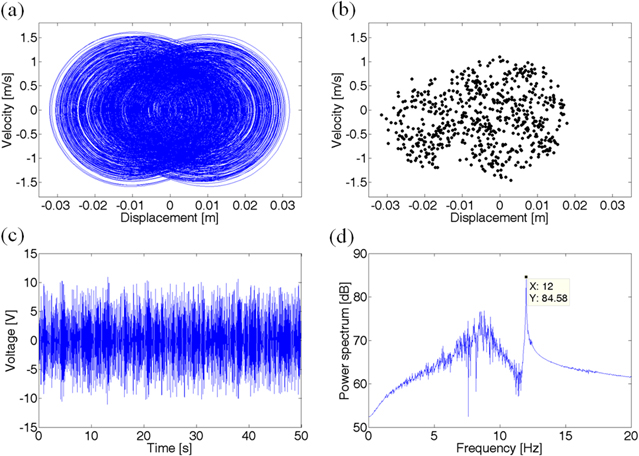
Figure 7. Harvester 1 at 12 Hz: (a) phase plot; (b) Poincare map; (c) voltage; (d) power spectrum.
Download figure:
Standard image High-resolution imageThe numerical results of Harvester 2 under the same excitation are shown in figure 8. Both the more regular phase plot and smaller area in the Poincare map verify that the responses of the two harvesters are different. It can be found from figures 8(c)–(d) that the main energy of the output voltage is at 12 Hz and there is comparative smaller energy distributed over 5–10 Hz. In brief, the two harvesters have different dynamic responses under either frequency-swept or fixed frequency excitations because of their different linear restoring forces.

Figure 8. Harvester 2 at 12 Hz: (a) phase plot; (b) Poincare map; (c) voltage; (d) power spectrum.
Download figure:
Standard image High-resolution imageAs the distance d is increased to 28 mm, the dynamic responses of the two harvesters are illustrated in figure 9. In this case, the high-efficiency frequency range of the DMEHS is 11–14 Hz. We also notice that Harvester 1 could harvest substantial energy in frequency range of 4–10 Hz since it does nonlinear vibrations during this frequency range as shown in the first plot of figures 9(a)–(b). When the distance d is further increased to 39 and 50 mm, the output voltage responses in these two cases are shown in figure 10. In the case of d = 39 mm, the difference between the output voltage under up-sweep and down-sweep in the DMEHS is more obvious than that in the case of d = 50 mm. The main reason is that the magnetic force in the former case is much stronger than that of the latter case. It is also observed that the same magnetic force produces a greater influence on Harvester 1 because its linear stiffness is smaller. In these two horizontal distances, each coupled harvester in the DMEHS has similar nonlinear responses with traditional 1-DOF monostable harvesters which have one frequency jump under harmonic frequency-swept excitation [15–19]. Thus, the proposed DMEHS exhibits monostable behaviors in either d = 39 mm or d = 50 mm case.

Figure 9. Numerical responses in the case of d = 28 mm: (a) and (b) are simulations of Harvester 1 under up-sweep and down-sweep, respectively; (c) and (d) are simulations of Harvester 2 under up-sweep and down-sweep, respectively.
Download figure:
Standard image High-resolution image
Figure 10. Numerical output voltages: (a) and (b) stand for output voltage of Harvester 1 and Harvester 2, respectively, in the case of d = 39 mm; (c) and (d) stand for output voltage of Harvester 1 and Harvester 2, respectively, in the case of d = 50 mm.
Download figure:
Standard image High-resolution imageIt can be concluded from above numerical investigation that the effective bandwidth of the DMEHS will be enhanced by changing the horizontal distance d. The effective frequency range of the DMEHS mainly depends on the linear parameter values of each independent harvester without magnetic coupling, the horizontal distance between the two harvesters, and the size and property of endmost magnets. The broadband energy harvesting using DMEHS can be obtained through the proper design.
4. Experimental verification
The experimental setup is shown in figure 11(a). The excitation signal is produced by a signal generator being amplified via a power amplifier, and then it is delivered to a vibration exciter. Generated base excitation will actuate the proposed energy harvesting system. Figures 11(b)–(c) show the DMEHS is in statically stable equilibrium points of the co-bistable structure.

Figure 11. (a) Experimental setup; (b)–(c) the DMEHS in experiments.
Download figure:
Standard image High-resolution imageFigure 12 shows the comparison between numerical and experimental results in the case of d = 24 mm. The predicted output voltage corresponding to excitation frequency agrees with experimental results. For the Harvester 2, the experimental output voltage is a little more irregular than simulation. From a general view, the dynamic responses of the two coupled harvesters in experiments are more similar than that in simulation. What is more, the DMEHS has an effective frequency range of 9.5–14 Hz, which covers the resonant frequencies of two linearly separated harvesters without magnetic coupling.

Figure 12. Numerical and experimental responses (d = 24 mm): (a) and (b) are results of Harvester 1 under up-sweep and down-sweep, respectively; (c) and (d) are results of Harvester 2 under up-sweep and down-sweep, respectively.
Download figure:
Standard image High-resolution imageFigures 13(a)–(b) shows the output voltage response at 11 Hz excitation. Each coupled harvester has an energy concentration at 11 Hz according to the power spectrum of the experimental output voltage. Experimental results also indicate that the output voltage of each harvester is not singly periodic, but the output voltage of Harvester 1 is more irregular because its power spectrum owns a wider frequency range. The two coupled harvesters' voltage responses and their corresponding power spectrum under the same excitation level at 12 Hz are shown in figures 13(c)–(d). It can be observed from their power spectrum that the bandwidth of the output voltage generated by Harvester 2 becomes narrower in comparison to Harvester 1.

Figure 13. Output voltage and power spectrum: (a) and (b) respectively stand for Harvester 1 and Harvester 2 at 11 Hz; (c) and (d) respectively stand for Harvester 1 and Harvester 2 at 12 Hz.
Download figure:
Standard image High-resolution imageWhen d is increased to 28 mm, numerical and experimental results are shown in figure 14. It can be seen that the two harvesters in the DMEHS can harvest energy in the frequency range of 5–14 Hz. The nonlinear magnetic coupling between the two harvesters in this distance becomes mildly weaker compared with that in the case of d = 24 mm. As d is further increased to 39 mm, the nonlinear magnetic force continues to reduce. The corresponding numerical and experimental results are exhibited in figure 15. The output voltages and the nonlinear dynamic responses of the two coupled harvesters are similar with that of traditional 1-DOF monostable harvesters. The voltage response demonstrates that there is only one equilibrium point in the case of d = 39 mm. This also can be verified by comparing the magnetic force with the linear restoring force in this distance.

Figure 14. Numerical and experimental responses (d = 28 mm): (a) and (b) are results of Harvester 1 under up-sweep and down-sweep, respectively; (c) and (d) are results of Harvester 2 under up-sweep and down-sweep, respectively.
Download figure:
Standard image High-resolution image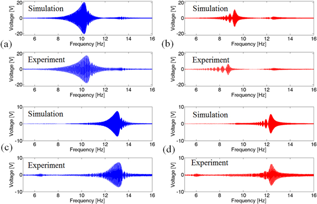
Figure 15. Numerical and experimental responses (d = 39 mm): (a) and (b) are results of Harvester 1 under up-sweep and down-sweep, respectively; (c) and (d) are results of Harvester 2 under up-sweep and down-sweep, respectively.
Download figure:
Standard image High-resolution imageOverall, the simulation and experimental results are in good agreement and the discrepancies are in a reasonable range. By changing the horizontal distance d, the proposed DMEHS can improve vibration energy harvesting performance by linking the natural resonant frequencies of the two harvesters and offering a wider effective frequency range of 5–14 Hz.
In order to verify energy harvesting improvements of the proposed system, comparison of the output power ( of the DMEHS and two separate harvesters without magnetic coupling is shown in figure 16. The output power area for each case in figure 16 may represent the energy harvesting ability. Therefore, the trapz command of MATLAB software is used here to calculate these areas. It should be clear that the area of overlap is not double-counted. The output power areas of the coupled Harvester 1 and coupled Harvester 2, respectively, are 287% and 260% of their linear counterparts. Although the peak values of the output power generated by linear harvesters are larger than that of the DMEHS, the bandwidth of the latter is wider. The wider bandwidth makes the harvesters own the better robustness to ambient vibrations. If the frequency range where the output power of harvests is larger than 4 μW is considered to be effective, the effective frequency range of the coupled Harvester 1 is 8.3–13.9 Hz which is 467% of that (from 9.6 to 10.8 Hz) of the linear Harvester 1. Meanwhile, the bandwidth of the coupled Harvester 2 is 3.19 Hz (from 10.4 to 13.59 Hz), while the bandwidth shrinks to be 0.6 Hz (from 12.4 to 13 Hz) in its linear case.

Figure 16. Comparison of the output power: (a) Harvester 1; (b) Harvester 2.
Download figure:
Standard image High-resolution image
5. Conclusion
Theoretical model and experimental verification of a nonlinear DMEHS are presented to demonstrate the performance enhancement of energy harvesting from ambient vibrations. The inclination angle of endmost magnets and the horizontal displacement are considered to model the interactive magnetic force between the two coupled harvesters. The simulation matches well with experimental results under harmonic excitations. Therefore, the proposed magnetic force model can be used to predict the output voltage and optimize nonlinear magnetic coupling harvesters. The adjustable horizontal distance between the two coupled harvesters in the DMEHS makes it possible to generate different magnetic force and exhibit various nonlinear characteristic responses, which could enhance vibration energy harvesting.
When the appropriate horizontal distance is designed, numerical and experimental results demonstrate that the DMEHS exhibits co-bistable characteristics with three equilibrium points (two are stable). Compared with the traditional 1-DOF bistable structure, the co-bistable structure possesses more complex varying pattern of the magnetic force due to the simultaneous motion of the two oscillators. Numerical and experimental results verify the broadband performance enhancement by adjusting the horizontal distance between the two harvesters. It is also found that the DMEHS will exhibit monostable characteristics when the horizontal distance is large enough.
The effective frequency bandwidth of the DMEHS mainly depends on the linear parameter values of each independent harvester without magnetic coupling, the horizontal distance between the two harvesters, and the size and property of endmost magnets. If more harvesters with magnets are designed in three-dimensional space based on the proposed system, a more complex energy harvesting system may be obtained to efficiently harvest energy from ambient vibrations. In the purpose of exploring the better performance of vibration energy harvesters, the optimizing strategy for nonlinear structures under the given excitation condition will be an important task in future research.
Acknowledgments
This project has been supported by the National Natural Science Foundation of China (Grant No. 51421004), Program for New Century Excellent Talents in University (Grant No. NCET-12-0453) and Fundamental Research Funds for the Central Universities of China (Grant No. CXTD2014001).