
Abstract
Modern compact and low power sensors and systems are leading towards increasingly integrated wearable systems. One key bottleneck of this technology is the power supply. The use of energy harvesting techniques offers a way of supplying sensor systems without the need for batteries and maintenance. In this work we present the development and characterization of two inductive energy harvesters which exploit different characteristics of the human gait. A multi-coil topology harvester is presented which uses the swing motion of the foot. The second device is a shock-type harvester which is excited into resonance upon heel strike. Both devices were modeled and designed with the key constraint of device height in mind, in order to facilitate the integration into the shoe sole. The devices were characterized under different motion speeds and with two test subjects on a treadmill. An average power output of up to 0.84 mW is achieved with the swing harvester. With a total device volume including the housing of 21 cm3 a power density of 40 μW cm−3 results. The shock harvester generates an average power output of up to 4.13 mW. The power density amounts to 86 μW cm−3 for the total device volume of 48 cm3. Difficulties and potential improvements are discussed briefly.
Export citation and abstract BibTeX RIS
1. Introduction
In an increasingly mobile world it is the focus of research groups across different disciplines to achieve ever-improved miniaturization while also reducing the power consumption of devices and systems from sensors to wireless transceivers. These achievements gradually make a battery-free world appear more feasible as an increasing number of applications can be powered autonomously using energy harvesting devices, i.e. devices capable of generating energy out of what is available in their surrounding environment. The field of energy harvesting is comprised of various physical transduction types which can translate different forms of energy into electrical energy. The largest portion of devices presented so far focusses on harvesting kinetic energy, e.g. from machine vibrations. Energy harvesting for body-worn or body-attached applications has seen a significant amount of research interest as it can potentially provide the solution for powering modern low-power sensor systems and increase the mobility and independence of the user. Previous investigations have shown that several dozens of Watts are expended in the human gait [1] which is a feasible energy source for human motion harvesters and will be the focus of this work.
However, a wide range of challenges has to be dealt with in order to not only guarantee the technical functionality of the harvesting device but also the applicability and the practical feasibility.
From the application point of view, the power supply unit, including the energy harvester, power management and energy storage, has to provide a specified amount of energy for the operation of the application. This operation can be continuous or triggered at certain time intervals to fulfill its task. The harvester has to be designed accordingly. In turn this requires a certain minimal device size as the power output of the harvester system is directly related to the size of the electromechanical transducer. In the case of inductive harvesters this could for example translate into large magnets and in piezoelectric devices into a large number of active layers.
The aforementioned requirement of a certain device size is in conflict with the aspects of integration. In order to be able to integrate an energy autonomous system into clothing, the main technical obstacles to overcome are the device size, its weight and the cost of the device. Hence a trade-off has to be found between a device size and transducer configuration which can fulfill the power requirements, but also satisfy the restrictions posed by the integration process. Depending on the particular application it might be necessary to develop a harvester rather large in size and weight, while on the other hand the device is expected to be small and lightweight to facilitate the integration as well as to retain wearing comfort. Additionally it depends upon the particular application how the device size is distributed. The obvious location to place a harvester within a shoe is in the shoe sole, therefore the longest dimension lies along the length of the shoe. The space along the width of the shoe is more limited and the height of the device is highly restricted, therefore a device would have to be comparatively flat, while there is some freedom with the choice of the surface area.
In the following section the key characteristics of the human gait are briefly outlined before an overview of previously presented human motion harvesters is given in section three. The fourth section describes the development of an inductive swing-type harvester that exploits the swing motion of the foot during walking. A shock-excited inductive harvester that exploits the impact of the foot with the ground is presented in the fifth section. A critical comparison of both types of human motion harvesters is then given in the concluding section.
2. Human gait as an energy source
The human gait exhibits three suitable sources of energy for energy harvesting devices, which are schematically depicted in figure 1. There are two acceleration-based excitation sources, namely the acceleration pulse upon heel strike, i.e. the impact between shoe and ground, and the acceleration due to the leg swing during walking. The other excitation source is the force that acts upon the shoe due to the weight of the person. As far as the force acting upon the shoe sole is concerned, previous investigations have shown that the force can dynamically amount to up to 130% of the person's body weight [2] and therefore easily reach values of 1000 N.
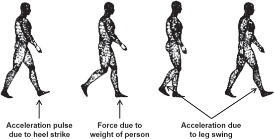
Figure 1. Schematic of the excitation conditions available in the human gait.
Download figure:
Standard image High-resolution imageThis paper focuses on the two acceleration-based excitation sources as potential energy sources for harvesting energy from the human gait. Therefore, acceleration measurements were performed at constant running velocities of 4 km h−1, 6 km h−1, 8 km h−1 and 10 km h−1 on a treadmill. A three-axis accelerometer was firmly attached to the sole at the back of a shoe. For a shoe lying flat on the floor, the x-axis of the acceleration sensor was in line with the vertical axis of the shoe pointing down to the ground whereas the z-axis was in line with the horizontal axis of the shoe. The accelerations were recorded with a duration of one minute for each motion speed.
Figure 2 shows 5 s time-frames of the recorded data along the mentioned axes. The data shown was recorded at 4 km h−1 and 10 km h−1, thus giving an overview of the acceleration patterns for both walking and jogging.

Figure 2. Recorded accelerations for runner 'KY' and speeds of 4 km h−1 in panes (a) and (b) and 10 km h−1 in panes (c) and (d).
Download figure:
Standard image High-resolution imageThe key observation made for the acceleration data is the large value of the acceleration peaks. On the vertical axis accelerations can peak at nearly 50 g while on the horizontal axis they can peak at approximately 20 g.
Table 1 summarizes the average acceleration peaks for the full data recordings for the x and z axis and two different runners respectively. On the x axis positive values correspond to a downward motion of the foot while on the z-axis the positive values correspond to a backward motion of the foot.
Table 1. Average acceleration peaks recorded during treadmill runs.
| Positive peak average (g) | Negative peak average (g) | ||||||||
|---|---|---|---|---|---|---|---|---|---|
| Person KY | Person DH | Person KY | Person DH | ||||||
| Motion speed | x-axis | z-axis | x-axis | z-axis | x-axis | z-axis | x-axis | z-axis | |
| 4 km h−1 | (slow walking) | 5.2 | 4.4 | 6.4 | 2.9 | −10.2 | −3.7 | −10.5 | −4.9 |
| 6 km h−1 | (fast walking) | 7.9 | 5.8 | 5.5 | 5.3 | −21.7 | −6.6 | −16.3 | −5.8 |
| 8 km h−1 | (slow jogging) | 8.8 | 8.1 | 4.7 | 6.1 | −27 | −10 | −21.6 | −7.8 |
| 10 km h−1 | (fast jogging) | 13 | 13 | 9 | 9.7 | −33.5 | −13.7 | −33.6 | −11.4 |
Two different runners with different body geometries were recorded with runner DH being lighter and taller, while runner KY is heavier and smaller. While these values are of limited statistical significance as they represent only two person's walking style and body geometry, the magnitudes of the accelerations indicate the applicability as an excitation source for energy harvesters.
A distinctive feature of walking is the very low frequency at which successive footsteps occur. As shown in table 2. Step frequencies for two persons at various motion speeds. The step frequency of one foot varies between 0.8 Hz and 1.2 Hz as a function of motion speed. It can be seen that there is only a moderate increase in the step frequency with increasing motion speed. Towards higher motion speed the increase in step frequency diminishes, implying that it is the step length which has to increase to allow faster motion.
Table 2. Step frequencies for two persons at various motion speeds.
| Motion speed | Step frequency: person KY | Step frequency: person DH | |
|---|---|---|---|
| 4 km h−1 | (slow walking) | 0.82 Hz | 0.8 Hz |
| 6 km h−1 | (fast walking) | 1 Hz | 0.94 Hz |
| 8 km h−1 | (slow jogging) | 1.18 Hz | 1.2 Hz |
| 10 km h−1 | (fast jogging) | 1.19 Hz | 1.19 Hz |
Due to the low excitation frequency, a potential harvesting device cannot be continuously operated in resonance mode (i.e. excitation frequency equal to eigen-frequency of energy harvester) as it is typically possible with machine vibrations of higher frequencies. Therefore, other concepts must be chosen, for example frequency up-conversion techniques or non-resonant techniques.
3. Reported devices
3.1. Force-driven harvesters
The large forces available upon heel-strike have motivated the development of several force-driven energy harvesting devices. The bending of piezoelectric materials attached to the shoe sole, both ceramics and polymer-based, was employed early on [3] leading to average power outputs of 1.8 mW and 1.1 mW respectively for a walking frequency of 1 Hz.
A generator using a lever and mechanical gears to translate the downward motion of the foot into a rotational motion coupled into a classical generator was also presented in [3]. While the device was rather large and heavy, it was able to generate an average power of 230 mW. A different approach employs the triboelectric effect, which is based upon materials of different electrochemical potential coming into contact, to generate maximum power outputs of up to 4.2 mW with a stacked structure which was pressed by a human palm [4]. Further force-driven devices can be found in [5–7].
3.2. Acceleration-driven harvesters
Particularly concerning the acceleration impulses available upon heel-strike, there has been only limited work. In [8] a piezoelectric macro scale prototype is presented. A heavy cylindrical mass is set into motion when the foot is lifted to form an angle with the ground. Magnets attached to piezoelectric beams snap towards this mass when it comes into range and vibrate freely at their resonance frequency, when released. This large device was able to generate a maximum power output of 2.1 mW at an excitation of 2 Hz in a laboratory setup. A second device incorporates a shoe-mounted piezoelectric vibrating cantilever and was presented in [9]. In this device the mass attached to a piezoelectric cantilever is displaced when excited by the acceleration impulses induced by heel strike. The corresponding spring-mass system then starts to vibrate at its eigen-frequency. As a result, a classical damped response occurs at every heel-strike. A power output of about 14 μW was achieved when walking at normal speed. By means of a sensitivity analysis based on a numerical model optimal parameters were identified, which provide the largest power output. Using the optimum parameters a power output of 395 μW was predicted. In both cases described, the energy harvester mechanism is based on a frequency up-conversion technique.
In the case of linear swing-type harvesters a number of devices have been reported. The shoe-integrated prototype upon which parts of this work are based was presented in [10]. It consists of a single generating magnet that can swing freely within a PVC channel placed within the sole along the horizontal axis. Two coils are placed in precise positions in order to overlay the coils' voltage signals and double the output while requiring only one rectifying circuit. This device was able to generate average powers up to approximately 10.5 mW on a treadmill run at a velocity of 10 km h−1.
A different device based on the magnet-in-channel setup was presented in [11]. Different configurations of the coils, channels and magnets were investigated, leading to an average power output of up to 14 mW at a walking velocity of two steps per second (1 Hz) for the best configuration found. However, this device did not use synchronized coil signals and would therefore require multiple rectifying circuits for more than one coil when used in a sensor system.
The acceleration-driven harvesters mentioned so far have the common problem of a large device size which greatly reduces their acceptability for an integration in shoes which in turn is hardly possible without altering the shoes appearance. As a consequence it is of utmost importance to reduce the device size and particularly the height of the harvesters while trying to reduce scaling effects and the loss of generated power due to down-scaling in size.
4. Swing-motion harvester
This section describes a harvesting device which exploits the swing motion of the foot. A first rather large prototype was presented in [10]. On the basis of the previously gained experience the aim of this work is to develop a smaller device with particular focus on a reduced device height in order to facilitate the integration into shoes.
4.1. Design
4.1.1. Introduction
For the miniaturized device a multi-coil configuration was chosen since a larger power output in contrast to a single coil design was expected. The magnets are concentrically placed in line separated by ferromagnetic steel spacers, creating an elongated stack as indicated in figure 3(a). Two neighboring magnets always show opposing polarization. The repulsive flux lines are therefore forced into the spacer and guided sideways as shown schematically in figure 3(b). This guarantees that each coil experiences several changes in direction of the magnetic flux within each step as several magnet-spacer sections pass by the coil. The coils are placed at equal intervals according to the distance between the magnets and connected in series. Because of this placement the magnets move through the coils simultaneously, i.e. every magnet enters a coil at the same time and with the same velocity. The alternating magnetic flux thus induces a voltage in every coil simultaneously, enabling the superposition of the voltage across the series connected coils, thereby reducing the requirements posed for the power management electronics, which in the simplest case can be a single rectifying circuit. Stopping magnets (SM) are introduced in order to prohibit the magnet stack from hitting the channel end at high velocities as this impact can clearly be felt in the shoe without cushioning and increases discomfort.
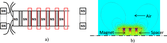
Figure 3. (a) Schematic of the magnet stack. Magnets separated by spacers (gray). Stopping magnets at either channel end. Coil positions indicated in red. (b) FEM simulation showing the magnetic flux as it is guided through the spacers. Areas of high flux density marked in magenta.
Download figure:
Standard image High-resolution image4.1.2. System model
The system model (figure 4) follows the differential equation shown in (1). Apart from the real-world acceleration data, which is used as input to the system, a number of different forces acting upon the moving magnet are also considered.

Figure 4. Block diagram showing the forces acting in the differential equation of the system model.
Download figure:
Standard image High-resolution imageThe friction forces between the magnet stack and the channel are calculated based on the weight of the magnet and the centripetal force built up during the swing motion of the foot, which acts as an additional normal force.
Air compression due to the air pushed in front of the magnet stack can be a highly limiting factor if no outlet is provided. In order to capture most of the magnetic flux within the coils, they are placed as closely to the magnets as possible. The channel is designed accordingly, leaving little space for air to pass by the magnet stack when it is moving. The model calculates the forces due to air compression by determining the volume change in the air pockets to the left and right of the magnet train at discrete time steps as the magnet moves. Thereupon one can estimate the exhaust velocity at the air outlet and the corresponding volume of air that is leaving the air pockets through the outlets. The differences in volume change between the air pockets and the corresponding differences in pressure can then be used to estimate the acting forces. Rubber stoppers were used in the fabricated setup and were modeled as a semi-elastic impact after first experiments showed that the influence of the SM on the moving magnet stack led to a greatly reduced range of motion.
As the magnet stack moves through the channel due to the external excitations, a voltage is induced in the surrounding coils and current flows through the coil windings. This current causes a magnetic field, which opposes the field of the magnet stack and thereby exerts a force on the magnets.
The equation of motion is given in (1) and considers the external acceleration input due to the foot motion  , the forces due to air compression
  , friction forces
  and the electrical damping force

In order to determine the power generated in the coils and the electrical damping force, the spatial distribution of the magnetic flux density is calculated using FEM software. A steady-state axisymmetric problem is set up using the software FEMM. Asymptotic boundaries are defined at a distance of 2 cm from the magnet stack. The magnetic flux density is extracted from FEMM along the area corresponding to the coil area. The coupling coefficient is calculated using the FEM data according to equation (2), where k is the coupling coefficient, φ is the magnetic flux and x is the axis of motion:

The coupling coefficient reaches its highest values between two magnets where a change in the flux direction occurs (figure 5). A more detailed description of the calculation of the coupling coefficient and consequently the generated voltage can be found in [12].
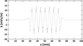
Figure 5. Coupling coefficient k for the outer coil cells along the direction of the magnet stack. Simulation performed with a total of 14 magnets and 13 spacers.
Download figure:
Standard image High-resolution imageThe software model implemented in Matlab/Simulink calculates the motion of the magnet stack from the sum of the forces listed in equation (1). The curve representing the spatial distribution of the coupling coefficient is shifted in position along the x axis, thus modeling the motion of the magnetic field. As the coils are placed in predetermined places and with fixed spacing, each coil experiences a separate magnetic flux depending on its location and generates a voltage according to equation (3), where Uind is the voltage induced in the coils, B is the magnetic flux density and A is the cross-sectional area of the coil:
The electrical damping force can be calculated using the coupling coefficient k and the current i induced in the coils according to equation (4):

Each coil is divided into ten coil cells in order to represent the spatial extent of the coil more accurately. For each cell the value of the coupling coefficient at its location is determined, which improves the accuracy of the calculations. An optimum resistive load equal to the coil resistance (approximately 166 Ω) is used in the simulations.
4.1.3. Optimization
In order to meet the requirement of a reduced device height while generating the maximum power output, the magnet-in-channel model was optimized using the optimization software modeFrontier. The built-in multi-objective genetic algorithm 'MOGA-2' was used, which improves upon a given number of starting designs spread within the boundary conditions for a given number of generations to find the optimum design. The optimization was performed with a height constraint of 12.5 mm (15 mm including housing) and a length constraint of 62 mm (70 mm including housing).
The number of magnets to be used was determined by the optimization software. A trade-off has to be found between the number of magnets and the space available for magnet motion. A larger number of magnets greatly reduces the freedom of motion for the magnet stack.
The completed optimization run resulted in a total of 14 magnets with a magnet height of 2 mm. Combined with the spacers the magnet stack forms a long cylinder of 41 mm in length. Two neighboring magnets always show opposing polarization. Table 3 shows the geometrical parameters of the multi-coil harvester. Although cylindrical magnets were used in the system model, for practical reasons explained in the next section, ring magnets were chosen for the prototype device.
Table 3. Geometrical parameters of a multi-coil swing-type harvester.
| Parameter | Value |
|---|---|
| Number of magnets | 14 |
| Magnet height | 2 mm |
| Magnet outer diameter | 7 mm |
| Magnet inner diameter | 2.7 mm |
| Number of spacers | 13 |
| Spacer height | 1 mm |
| Spacer outer diameter | 7 mm |
| Spacer inner diameter | 2.7 mm |
| Number of coils | 13 |
| Coil length | 1.2 mm |
| Coil outer diameter | 12.5 mm |
| Coil inner diameter | 8.5 mm |
| Channel length | 62 mm |
| Magnet stack length | 41 mm |
4.1.4. Implementation
Several difficulties were encountered during construction of the device. Gluing magnets together against the repulsive forces due to their opposing polarization proved very challenging. Several designs were investigated as shown in figure 6. The designs were simulated and the expected power output normalized to 100% for the best design is shown.

Figure 6. Different magnet stack configurations: rotational axis on the left border of the graphs. Large rectangles indicate magnets, small rectangles indicate spacers. The two graphs on the right show ring magnet configurations.
Download figure:
Standard image High-resolution imageThe most practical design which uses ring-magnets and a supporting rod of non-ferromagnetic material in the free space at the center of the magnets shows a significant reduction in power output. Not only does this setup imply a reduced volume of active magnetic material but it also allows the magnetic field to partially short-circuit in the free space within the ring. This trade-off is acceptable for practical reasons, as it inherently allows the correct alignment of magnets and spacers with complete overlap. Additionally it facilitates the gluing process and especially when using a thread rod, the magnets can be held in place by screwing a nut onto either end of the rod. The fabricated prototype and its external placement on a shoe for characterization purposes are shown in figure 7.
4.2. Characterization
In order to analyze the performance of the device under real conditions, several treadmill runs were performed. A linear accelerator table was used for brief testing of the swing-type harvesters, however its attainable accelerations are limited to approximately 1 m s−2. Therefore the measured accelerations that occur during walking could not be replicated by other means than a treadmill.
As before, measurements were performed at four different motion speeds and for two runners of different body geometries. Figure 8 shows the measured power output of the harvester for runs performed on a treadmill and as a comparison for runs performed on the ground without a treadmill. It was reported earlier that with the transition from the abrupt motions of fast walking to the rather smooth motions of slow jogging, a decrease in power output can be observed [10]. This effect can be observed in figure 8 as well, where the curves do not show a steadily ascending slope. The fact that for runner 'KY' this drop in power output occurs at lower motion speeds than is the case with runner 'DH' is attributed to the walking style and the body geometry of the runners. Measurements were also performed at a reduced set of motion speeds for walking without a treadmill. While treadmill runs offer a certain level of reproducibility, some differences can be expected when compared to walking on the ground. First, on a treadmill one automatically makes alterations to the gait patterns in order to run smoothly. Second, the inherent spring-loaded characteristic of the treadmill causes the impact of the foot to be damped to a certain degree.
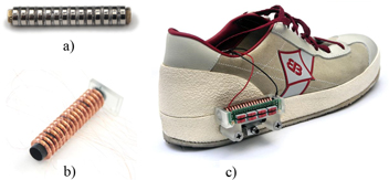
Figure 7. (a) Magnet stack mounted with nuts. (b) Multiple coils placed on plastic channel. (c) Harvester attached externally to the shoe in order to perform treadmill runs. An accelerometer is attached to the bottom of the harvester to synchronously record the accelerations.
Download figure:
Standard image High-resolution image
Figure 8. Power measurements for two runners at optimal load resistance (166 Ω). Walking speed on the ground without treadmill is an approximate value.
Download figure:
Standard image High-resolution imageAt the slowest measured speed of 4 km h−1 on a treadmill, the harvester was able to generate 0.34 mW and 0.46 mW for the two runners. At approximately the same speed on the ground, power outputs of 0.375 mW and 0.526 mW were achieved. It can also be noticed that the maximum achieved power output of 0.81 mW for 'ground walking' is measured at 5 km h−1 and thereby at a speed 1 km h−1 slower than on a treadmill, where a nearly identical power output of 0.84 mW is achieved at 6 km h−1. It can therefore be assumed that the power output during normal walking without a treadmill is slightly larger than for treadmill runs, independent of the motion speed.
Figures 9(a) and (b) depict the measured voltage and power output respectively for approximately one step for runner KY at a speed of 6 km h−1. It can be seen from the figures that each step shows two characteristic impulses corresponding to the two major motions of the foot (forward and backward movement). Each waveform is made up from a number of consecutive peaks, which represent the change in flux direction between the coils of the magnet stack. The total energy per step can be obtained by integrating the power over one such step and its two impulses.

Figure 9. (a) Enlarged section of the voltage output at a speed of 6 km h−1 for runner KY. Each step shows two characteristic impulses, representing the two major foot motions. (b) Corresponding power output calculated from the voltage signal.
Download figure:
Standard image High-resolution image4.3. Discussion
The previous sections show that the miniaturization of a swing-type harvester through means of parallelization can be achieved without the devices power output dropping into unfeasible ranges. However, it has to be kept in mind that with a maximum recorded average power output of 0.84 mW the reduction due to scaling effects is significant as compared to [10]. The volume scales quadratically with the radius and thus the mass of the magnet stack, which is the inertial mass of this system, was greatly reduced from approximately 50 g in [10] to 9.8 g in this work. Not only does this result in reduced inertia of the magnet stack, but it also results in a reduced magnitude of the magnetic field due to the smaller magnets and consequently in a reduced power output. In practical terms the reduction in size is a great advantage, as the device with a total height of 15 mm including the housing is now far easier to incorporate into shoes. With a total length of 70 mm including housing it can also be integrated into the heel section of a shoe and is not negatively affected by the bending of the front part of the sole during walking.
Concerning the modeling of the device, a complete match between simulation and measurement for all velocities has not been achieved so far. Figure 10 shows a comparison between the simulated and measured power outputs for both runners. Apart from differences caused due to the simple physics, errors are introduced by the discrete nature of the calculations performed, e.g. the magnetic flux density is calculated at fixed spatial intervals and used to determine a mean flux within each coil. The accuracy of this approximation depends on the step size. An increased resolution leads to a manifold increase in computing time as both the FEM simulation and Matlab have to perform an increased number of computations  . Concerning the optimization algorithm which calculates hundreds of designs, a balance has to be found between computing time and accuracy. Additionally, it is assumed that the speed-dependent effects of the system model require further improvement.
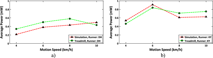
Figure 10. Comparison between simulated and measured power output shown for runner DH in pane (a) and runner KY in pane (b).
Download figure:
Standard image High-resolution imageTherefore future work clearly includes improvements to the reproduction of real-world physics within the system model and the approximations used in the model, which continually leads to a better match between simulation and measurements. The influence of the calculation resolution on the model accuracy is not considered in this work.
The model was limited in flexibility as it was designed to simulate a fixed number of coils equal to the number of flux transitions between magnets. If the algorithm calculated a design with 14 magnets, the number of coils in the simulation would be set to 13. To avoid this limitation a fully flexible model is being worked on, which can calculate designs where the number of coils is independent from the number of magnets. Further improvement through a new design in a new optimization run is expected.
5. Shock-excited harvester
The second acceleration-based excitation source relates to the acceleration pulses upon heel-strike. A shock-excited energy harvester based on a frequency up-conversion technique appears to be a practical solution for converting acceleration pulses into usable electrical energy. In the following sections the design and characterization of such a device with dimensions of 60 × 40 × 20 mm3 is described.
5.1. Design and parameter optimization
As discussed for the swing-motion harvester, the usability of a device for energy harvesting from human motion depends strongly on its integration capability and thus on its size. Therefore, a strict constraint on the device size was also applied to the shock-excited energy harvester. For integration of the energy harvester into the heel of a shoe, the total height of the device must not exceed a limit of 20 mm. The width and length of the device were restricted to 40 mm and 60 mm, respectively. Applying these size constraints, an integration of the device into the heel of a shoe is feasible.
For converting the acceleration pulses into electrical energy an electromagnetic conversion mechanism was chosen. Due to the limited device height, the shock-excited energy harvester incorporates a magnetic circuit, which contains two air gaps. In this manner a reasonably flat design is achievable without losing too much volume for the active components (coil volume, magnet volume). A schematic diagram of the energy harvester structure (cross-section) including relevant design parameters is shown in figure 11(a). The total width of the structure Wtotal, which is equal to 33 mm, follows from the total device width (40 mm) less the thickness of the housing and some air gap on both sides. The gap between coil and magnet was chosen to be 0.5 mm. The width of the coil Wcoil follows from the dimensions of Wsheet, Wmag and the gap between magnet and coil. The height of the back iron sheet Hsheet, which is equal to two times the height of the magnet Hmag, is limited by the maximum height of the device and the internal displacement amplitude zmax. There will be a trade-off between the parameters Hmag and zmax. A large magnet height will increase the magnetic volume and the seismic mass. However, this is at the expense of the internal displacement amplitude. A small internal displacement will induce impacts at the mechanical stoppers more often. The magnet height also depends on the availability of magnets with a particular height. In this first design, a magnet height of 5 mm was chosen resulting in a height of 10 mm for the back iron sheet. Considering a total device height of 20 mm and a thickness of the housing of 2 mm, the internal displacement amplitude yields to 3 mm. The following design parameters are still variable and must be optimized with respect to the power output: the width of the magnet Wmag, the width of the back iron sheet Wsheet and the outer diameter of the coil Dcoil. The value for Lmag and Lsheet is equal to Hsheet. The inner diameter of the coil is 2 mm.
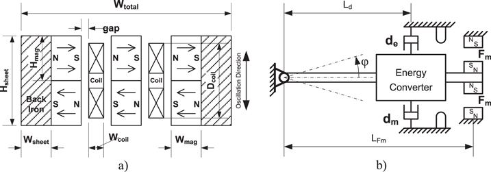
Figure 11. Shock-excited energy harvester: (a) schematic diagram (cross-section) of the active energy conversion structure showing the magnetic circuit and coils, (b) simplified model of the energy harvester including the nonlinear force Fm of the magnetic spring, mechanical stoppers and electrical and mechanical damping.
Download figure:
Standard image High-resolution imageThe energy conversion structure of the shock-excited energy harvester is suspended using two pairs of magnets with opposite polarity. The outer suspension magnets are fixed within the housing (base and lid). The size of the magnets can be varied for adjusting the magnetic suspension force with respect to the excitation conditions. Larger or smaller magnets will change the stiffness in the system and thus the eigen-frequency can be varied.
For optimization of the variable design parameters a system model based on differential equations was developed and implemented in MATLAB/Simulink. A schematic diagram of the system model is shown in figure 11(b). The rotational motion of the cantilever arm is described by the following differential equation:

where  is equal to the sum of all torsional moments in the system. The moments induced by weight are summarized as following:

where g is the gravity of earth, mtot is the total mass in the system and Leff is the effective length with respect to the center of gravity of the total mass. The external excitation also generates torsional moments as described in equation (7):

where A is the excitation acceleration. Further torsional moments are induced by the electrical damping force Fd,e and the mechanical damping force Fd,m. The associated moment arm is the distance  . The general moment is given by:

The index j accounts for either electrical or mechanical damping forces. The electrical damping force Fd,e, which originates from the Lorentz force, results from the coupling factor CF and the current i in the coil:

From equation (9) follows that the electrical damping force Fd,e can be represented by a velocity proportional damping element with the electrical damping coefficient:

In the same way, the mechanical damping force Fd,m is proportional to the angular velocity with the mechanical damping coefficient dm:

The mechanical damping coefficient was determined experimentally. The magnetic force Fm between the repulsive magnets changes with the variable in a nonlinear manner and introduces a stiffness into the system. The magnetic force hereby generates a torsional moment as following:

The magnetic force as a function of displacement angle was numerically calculated using the FE-method. The set of equations described above represents the model of the shock-excited energy harvester and was solved numerically.
The implementation of the shock-excited energy harvester is shown in figure 12 (the lid is removed). The rim of the housing is reinforced using steel bolts in order to increase the robustness of the device (figure 12(a)). The outer suspension magnets are accommodated in the base and the lid. Between the anchor and the active structure is enough space for a power management circuit. Figure 12(b) shows a side view of the energy harvester structure. The device was integrated into the sole of a shoe for characterization and testing.

Figure 12. Implementation of the shock-excited energy harvester: (a) complete device (lid removed) including power management and wireless application module (b) side view showing the oscillating cantilever arm including magnetic circuit and suspension magnets.
Download figure:
Standard image High-resolution image5.2. Characterization
The shock-excited energy harvester was tested under realistic conditions on a treadmill. An example of the instantaneous voltage output during one step is depicted in figure 13(a). The overlaid acceleration signal shows an initial acceleration peak of about 18 g, which is caused by the heel-strike. The motion speed was 6 km h−1. The highest voltage peak is about 5.8 V and corresponds to a power output peak of 46 mW (reached at the third peak in figure 13(b)). During one step the active structure of the shock-excited energy harvester oscillates with about 16 periods of oscillations until the voltage amplitude drops below 1 V. The decay of the voltage response seems to be a more or less linear characteristic. A second displacement event of the active structure occurs 0.65 s after the first impact. At this moment the foot is lifted from the ground. However, the power output from this event is rather small.

Figure 13. (a) Voltage output with overlaid acceleration signal from a single excitation pulse at a motion speed of 6 km h−1; (b) corresponding power output.
Download figure:
Standard image High-resolution imageFigure 14 shows the power output for two different test persons as a function of walking speed. In general the power output at a specific motion speed depends on the test subject. At a motion speed of 4 km h−1 (slow walking) the power output is 1.25 mW for test person DH whereas just 1 mW is generated for test person KY. At motion speeds of 6 km h−1 (fast walking) and 8 km h−1 (slow jogging) a more significant difference in output power can be observed between the two test persons. Possible reasons are the differences in the walking style and in the physiognomy (e.g. weight of person, length of leg, etc) of the test persons. The maximum power output of ca. 3.5 mW appears for runner KY at a motion speed of 6 km h−1 (figure 14(b)). At a motion speed of 10 km h−1 the output power is just below 3 mW and is almost equal for both test persons. At this particular motion speed, the average of the acceleration peaks from heel-strike reaches up to 34 g. In addition to the treadmill runs, the power output was also measured for 'ground walking'. The maximum achieved power output was 4.13 mW at a motion speed of approximately 5 km h−1.
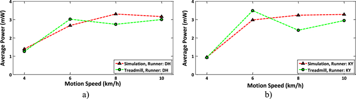
Figure 14. Average power output (simulation and measurement) at different motion speeds: (a) runner DH; (b) runner KY.
Download figure:
Standard image High-resolution imageThe simulation results obtained by the numerical model are also shown in figure 14. The power estimation is reasonably close to the experimental results. However, the drop in power output when the transition from the abrupt movements of fast walking to the smooth movements of slow jogging occurs is not apparent in the simulation data.
6. Harvester comparison and conclusion
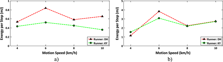
Two inductive harvesters based on different transduction principles were presented in this work. The first harvester exploits the swing motion of the foot to accelerate a magnet stack through a set of coils, while the second device employs frequency up-conversion to excite a spring-loaded magnetic circuit into resonance upon heel strike. Although based on different physical principles, both devices show similarities in the patterns of the power outputs. There is a drop in power output for both devices when the transition from the abrupt movements of fast walking to the smooth movements of slow jogging occurs. Both devices show a dependence of the test person. The more pronounced effect in the case of the swing-type harvester can be observed in the energy generated per step shown in figure 15. The fact that the shock-type harvester shows an equal generated energy for both runners towards higher motion speeds (figure 15(b)) may be attributed to the limited inner amplitude of the device, as the magnet swing reaches this limit at relatively low motion speeds and therefore limits the generated energy.
Figure 15. Average energy harvested per step for both runners: (a) swing type harvester; (b) shock-excited harvester.
Download figure:
Standard image High-resolution image
Difficulties arise for the shock-type harvester when the angle between the shoe and ground upon heel strike is considered. As the heel strike generally occurs at an angle, the energy is only partially coupled into the harvester built horizontally into the shoe sole. The swing type harvester is mainly limited by the freedom of motion of the magnet stack and hence the device length, which greatly affects the power output. The height constraint also limits the coupling as the coils surrounding the magnet stack are limited to flat structures, which in turn reduces the electrical damping of the magnet motion and thus the converted energy.
The highest average power output of 4.13 mW was measured on ground at a motion speed of 5 km h−1 for the shock-type harvester, while the highest measured average power of the swing-type harvester was 0.84 mW at a motion speed of 6 km h−1 on a treadmill. Considering the device volume (including housing) of 48 cm3 for the shock-type harvester and 21 cm3 for the swing-type harvester, this translates into a power density of 86 μW cm−3 and 40 μW cm−3 respectively.
One can see from the presented data that a reasonable power output can already be achieved at low motion speeds, with the data indicating that fast walking (6 km h−1) appears to offer the most energetic gait pattern within the considered range of speeds. However, a larger group of test subjects would be required to more precisely attribute the observed effects to the body geometries or gait styles.
In the case of the swing-type harvester, an improved model is in development which can handle a flexible and independent number of coils and magnets. First calculations have confirmed a significant increase in power output. A new optimization will be performed with the improved model and it is expected that a new prototype could close the power output gap to the shock-type harvester.
Acknowledgments
This research (IGF-Project: 17742N) was supported by the 'Programm zur Förderung der industriellen Gemeinschaftsforschung und -entwicklung (IGF, Germany)' and by the Federal Ministry of Education and Research (BMBF, Germany) under the contract 16N11843.