Abstract
Recent work has indicated that linear vibrational energy harvesters with an appended degree-of-freedom (DOF) may be advantageous for introducing new dynamic forms to extend the operational bandwidth. Given the additional interest in bistable harvester designs, which exhibit a propitious snap through effect from one stable state to the other, it is a logical extension to explore the influence of an added DOF to a bistable system. However, bistable snap through is not a resonant phenomenon, which tempers the presumption that the dynamics induced by an additional DOF on bistable designs would inherently be beneficial as for linear systems. This paper presents two analytical formulations to assess the fundamental and superharmonic steady-state dynamics of an excited bistable energy harvester to which is attached an auxiliary linear oscillator. From an energy harvesting perspective, the model predicts that the additional linear DOF uniformly amplifies the bistable harvester response magnitude and generated power for excitation frequencies less than the attachment's resonance while improved power density spans a bandwidth below this frequency. Analyses predict bandwidths having co-existent responses composed of a unique proportion of fundamental and superharmonic dynamics. Experiments validate key analytical predictions and observe the ability for the coupled system to develop an advantageous multi-harmonic interwell response when the initial conditions are insufficient for continuous high-energy orbit at the excitation frequency. Overall, the addition of an auxiliary linear oscillator to a bistable harvester is found to be an effective means of enhancing the energy harvesting performance and robustness.
Export citation and abstract BibTeX RIS
1. Introduction
Resonant inertial energy harvesters have received significant attention by researchers seeking to develop self-powered sensors [1], harvest human kinetic energy [2, 3], and expand our portfolio of renewable energy resources [4]. With maximum vibrational energy conversion achieved around a designed natural frequency, linear resonant harvesters are susceptible to a reduction in performance should the excitation conditions vary too greatly from the ideal sinusoidal form and frequency. Studies have thus multiplied with the aim of broadening the usable bandwidth of energy harvesting performance [5, 6]. One solution has been to directly append static or dynamic elements to the harvester to tailor or induce new modal behaviors that increase the number of frequencies at which the system is sensitive [7–13].
The extension of studies into nonlinear energy harvester design has introduced a means to broaden the performance bandwidth for a single device [5, 6]. Numerous recent investigations have recognized the great potential of bistable energy harvesting systems [14, 15]. The steady-state dynamics of bistable harvesters are primarily classified by two response regimes: small oscillations (low-energy orbits) around one of the stable equilibria or large oscillations (high-energy orbits) when the inertial mass vibrates from one stable state to the other during an excitation period. The latter high-energy orbit vibrations (also termed snap through) are beneficial for increasing power harvesting output. Since snap through is a non-resonant phenomenon, bistable harvesters may be more easily excited by realistic stochastic-type ambient vibration excitation, helping to justify their recent popularity within the research community [14, 15].
Given the enhancement and multiplication of energy harvesting dynamics obtained using add-on elements for linear harvester systems, it appears to be a logical extension that similar benefits may be acquired by appending such elements to bistable harvesters. However, because bistable snap through is not a resonant process, it is an inappropriate assumption that new modal-type or enhanced responses will be obtained with the addition of a degree-of-freedom (DOF). While there are a number of investigations in the general dynamics literature regarding the utilization of a bistable attachment as a vibration control implement to an excited linear oscillator [16–19], it appears that no work has been presented in the literature on the general dynamics of an excited bistable system with an auxiliary linear oscillator. Thus, there are no precedents from which to draw early conclusions as to the advantages possible in enhancing the energy harvesting performance of a bistable system by introducing an appendage linear oscillator.
Therefore, as stimulated by previous linear energy harvesting investigations [7–13], the aim of this paper is to explore the potential energy harvesting benefits attainable by the addition of a linear oscillator to an excited bistable energy harvester, figure 1. This study also serves as an initial investigation into the coupled high-energy dynamic responses of this configuration given the absence of related work in the literature. Because it is well known that nonlinearities in coupled systems will readily induce multi-harmonic effects [19–22], we are interested in a more complete dynamic evaluation encompassing both fundamental and superharmonic responses. In particular, we aim to assess the order-3 superharmonic which has been numerically and experimentally encountered in several bistable energy harvesting studies to date where just one bistable DOF was considered [23–25].
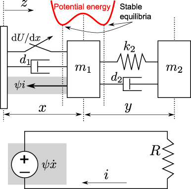
Figure 1. Schematic of a base-excited, inductive bistable energy harvester to which is attached a linear oscillator. The external harvesting circuit is shown at the bottom.
Download figure:
Standard image High-resolution imageSection 2 introduces the model formulations and means for predicting solutions. Section 3 compares the fundamental response of the high-energy dynamics for the bistable harvester with and without an appendage linear oscillator as system parameters are varied. Section 4 explores the additional influence of superharmonic dynamics upon harvesting performance. Section 5 presents the results from experiments conducted to verify key features of the analytical findings, while section 6 summarizes the conclusions of the research.
2. Modeling and solution formulation
2.1. System governing equations
A diagram of the system under investigation is provided in figure 1. An auxiliary linear oscillator of mass m2 is attached to an electromagnetic induction bistable energy harvester of mass m1 which is subject to base acceleration  . The lumped-parameter modeling approach follows that of many researchers who have shown that the primary mechanical responses of a variety of continuously distributed bistable energy harvester systems may be accurately modeled as 1DOF devices, including beams buckled via axial loads [24], magnetic repulsion [26], or magnetic attraction [27, 28]. In practice, such assumptions may be violated for bistable harvester systems if higher-order buckling modes are induced either as a consequence of the specific interaction between the excitation and the bistable device or due to the location of attachment of the auxiliary linear oscillator on the bistable harvester. In this work, such scenarios are assumed to be avoided by design. Moreover, the lumped modeling method is particularly relevant in light of the present experimentation which utilizes lumped inertial masses for the bistable and inertial bodies. In the modeling, the bistable electromagnetic transduction mechanism is assumed to have a low inductance and its output shunted by a resistive load R, where the relative motion x(τ) between the base z(τ) and the bistable harvester mass m1 induces a flow of current i(τ) in the harvesting circuit. The double-well restoring potential of the bistable device is

where position x = 0 is defined as the central, unstable equilibrium position of the double well, as illustrated in figure 1. The governing equations for the system may then be expressed as


where y is the relative displacement between the bistable inertial mass and the linear oscillator mass and ψ is an electromechanical coupling coefficient. For energy harvesters having an electrical time constant much smaller than the mechanical natural period, it is well known that the effects of external circuitry upon the mechanical response of the harvester are principally additional dissipative influences [1, 29–33], and this assumption is employed in constructing equation (4) from Kirchhoff's law. Following substitution and nondimensionalization, the governing equations may be represented as follows:


where the following constants are defined:

and ()' indicates a derivative with respect to nondimensional time t.
2.2. Problem formulation: one-term solution
The harmonic balance method is employed to solve the governing equations (5) and (6). For most basic response prediction, one-term solutions may be assumed of the form


where c1 is required due to the possibility that the bistable oscillator may vibrate around a non-zero stable equilibrium. The attached linear oscillator does not have a constant term in the expansion due to the notation that y represents a relative coordinate. The fidelity of results obtained via the harmonic balance method is limited by the number of harmonic terms used in the Fourier series expansion. The approach has been historically shown to be qualitatively and quantitatively accurate for both low-energy intrawell and interwell snap through dynamics [34] and has recently been revisited as an efficient analytical tool for bistable energy harvesting systems [25, 35, 36]. Finally, when applying the results of a steady-state analysis towards a realistic application, one is advised to evaluate the nearness of operating conditions to potential bifurcations which indicate the possibility of co-existing responses including aperiodic dynamics; a variety of useful analytical tools are available for these assessments [37–39].
We substitute equations (9) and (10) into (5) and (6), eliminate higher-order terms, and group the constant, sinωt, and cosωt terms to yield five governing equations for the slow-varying coefficients c1,a1,b1, a2, and b2,


where the following are defined:


The steady-state responses of the system are determined by solving the coupled equations (11)–(15). As such, equations (14) and (15) may be solved explicitly in terms of a1 and b1 to determine constants a2 and b2,


Equations (22) and (23) are substituted into (12) and (13) which are thereafter squared and summed to yield one equation for the bistable harvester response amplitude squared,  ,
,

given the following terms:


Given that the term Λ contains unknowns c1 and  , equation (11) is first solved under steady-state conditions and one choice of the parameter c1 is selected, depending on whether one is interested in intrawell, low-energy oscillations of the bistable oscillator (c1 ≠ 0) or interwell, high-energy vibration (c1 = 0). Then, c1 is substituted into Λ such that equation (24) is expressed fully in terms of a cubic polynomial of the parameter
  . The roots of equation (24) are then determined and the final coefficients are computed explicitly from


Having computed all five of the coefficients, the stability of the solutions  may be determined via a perturbation method, for example by Jacobian analysis [40].
This work also focuses on the phase relationships amongst the dynamic elements. Thus, the system response may be expressed alternatively from equations (9) and (10) as follows:


where ϕ1 and ϕ2 represent phase lags between the input excitation and the bistable harvester and linear oscillator displacements, respectively.
2.3. Problem formulation: two-term solution
The advantage of the one-term solution is the direct analytic expression, equation (24), used to determine the responses. However, the limited number of terms assumed in the Fourier expansion constrict the wider applicability of the results to realistic observations of nonlinear systems coupled to other linear or nonlinear DOFs which are known to more readily exhibit multi-harmonic dynamics [20–22]. As a result, the assumed solution form is now expanded with terms proportional to the fundamental and third harmonics, which is the result of the cubic nonlinearity assumption [22] and recent numerical and experimental observations of the third superharmonic in bistable energy harvesting studies [23–25].


Equations (33) and (34) are substituted into (5) and (6) and the coefficients of constant, sinωt,cosωt, sin3ωt, and cos3ωt terms are collected.

where the following are defined:


In the same manner as in section 2.2, the nine equations (35)–(43) are solved for steady-state conditions. Equations (40)–(43) are solved for coefficients g1,h1,g3, and h3 in terms of a1,b1,a3, and b3. Substitution of these expressions into the preceding equations (36)–(39) is carried out until, as before, equations (36) and (37) are squared and summed. Likewise, the decision regarding interest in studying low- or high-energy oscillations of the bistable device dictates the selection of the parameter c1 in solving and substituting equation (35) into this last squared–summed equation. However, unlike in section 2.2, there are two terms  and
and  to compute, which necessitates a second equation. Thus, the expressions for a3 and b3 are squared and summed to provide a second equation. Equations (52) and (53) represent the two coupled nonlinear response equations.


where K,Δ,Γ1, and Γ2 are provided in the appendix.
It is found that equations (52) and (53) are nonlinearly coupled by the terms  and
and  . Therefore, a numerical solution procedure is required. We utilize the MATLAB software command fsolve, as has been successfully employed in recent nonlinear vibration studies [41–43]. Having solved the equations for a given set of system parameters, the individual coefficients may be computed from the expressions provided in the appendix, and the stability of the solution may be checked via a perturbation method as in section 2.2.
2.4. Electrical power computation
The average power across the harvesting circuit resistive load R is computed from P = R|i|2/2. By equation (4) which relates the generated current to the harvester response and according to the solution forms equations (9) and (33), the amplitude of the generated power may be expressed as a sum of the respective harmonic displacement amplitudes, P = P1 + P3, where  and
and  . This practically represents the guiding assumptions of the method of harmonic balance that the total system response is the summation of unique harmonic contributions [25]. Consequently, depending on whether one considers the fundamental or superharmonic response magnitude, equation (47), the unique spectral components of the harvested power are computed. We set m1 and ω1 to unity to simplify expressions without loss of generality since other dimensionless groups of equations (7) and (8) are normalized to these parameters. The values of the generated power related to the fundamental and order-3 superharmonic are therefore determined, respectively, by equations (54) and (55).


In the following analytical investigations we utilize the parameters γ = 0.01 and ε2 = 0.04 to represent a mechanically lightly damped bistable harvester with an electromagnetic coupling strength typical of many inductive platforms [31, 32]. From equations (54) and (55), it is seen that the power is directly proportional to the response magnitude squared of the bistable harvester and thus the trends of the displacement amplitude correspond to the trends of the generated power. Therefore, for a more meaningful comparison against the bistable energy harvester without auxiliary linear oscillator, we assess the power density, which is the power normalized to the net mass of the system. The power density is computed from P1,3/(1 + μ) and is employed to evaluate the advantage obtained with the proposed configuration as compared to the individual bistable harvester.
3. Comparison of one-term responses with and without an auxiliary oscillator
3.1. Influence of the mass ratio, μ
To determine the effects of coupling on the fundamental system response, the roots of equation (24) were computed for the system parameters p = 0.2,β = 1,f = 1,γ2 = 0.001, and a range of mass ratios, μ = [0.003,0.01,0.1,0.3,1,2]. The harvester nonlinearity strength β may realistically be varied over a large range of values by tailoring the severity of the post-buckled state, and we here employ a value similar to that used in recent bistable energy harvesting studies [27, 28, 35]. The excitation level p used in this section represents a mild level with respect to its normalized definition in equation (7). For a more intuitive interpretation, a recent investigation determined that the normalized excitation level p = 0.2 was comparable to an absolute base acceleration of approximately 2.5 m s−2 for an individual bistable harvester beam of 8 g mass and linear natural frequency around 15 Hz [25]. It is recognized that high-energy interwell responses are most favorable in a steady-state energy harvesting context as compared to low-energy orbits [14] and, consequently, we focus only on the high-energy dynamics of the systems. The response amplitude, phase, and power density of the bistable inertial generator with and without the attached linear oscillator are shown in figure 2. The individual bistable harvester responses may be computed by setting μ = 0 in the analysis. The displacement magnitude and phase of the linear oscillator are plotted in figure 3.
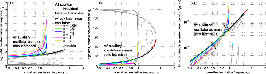
Figure 2. High-energy dynamics of the bistable harvester as the mass ratio μ changes. (a) Fundamental response amplitude r1, (b) response phase ϕ1 (degrees) and (c) power density P1/(1 + μ).
Download figure:
Standard image High-resolution image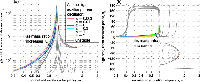
Figure 3. High-energy dynamics of the linear oscillator as the mass ratio μ changes. (a) Fundamental response amplitude r2 and (b) response phase ϕ2 (degrees).
Download figure:
Standard image High-resolution imageFigure 2 shows that for the smallest mass ratios, the results intuitively converge onto those computed without the appendage oscillator. As the mass ratio of the add-on linear oscillator increases, the consequence is a uniform amplification of the bistable harvester response magnitude for excitation frequencies less than the natural frequency of the linear oscillator (here f = 1 so that ω2 = 1). Greater mass addition yields more amplification above the displacement amplitude of the individual bistable harvester, figure 2(a). One trade-off is that the frequency at which enhanced high-energy dynamics are no longer sustainable may be less than that for the system without attached oscillator. (We note for completeness the general rule that where stable high-energy orbits are not predicted, this indicates that the system returns to the low-energy orbit [35].) While the generated power, which is directly proportional to the mechanical response amplitude squared as indicated by equation (54), is amplified uniformly below the linear oscillator natural frequency, the power density is enhanced in a bandwidth upper-bounded by this new cut-off frequency, figure 2(c). The lower bound of this bandwidth of performance improvement appears to be an inexact inflection point across the curve for the individual bistable harvester; in this case, the inflection of the lower bound occurs across a narrow band ω ≈ 0.769 for μ = 0.003 to ω ≈ 0.781 for μ = 2. Since the power density is what defines the advantage over the individual bistable energy harvester, enhancing this metric across the observed bandwidth translates into an improvement of the energy harvesting system.
The corresponding high-energy dynamics of the linear oscillator are shown in figures 3(a) and (b). Recall that in this example, the natural frequency of the appended oscillator occurs at ω = 1 since the tuning ratio is f = 1. Unlike a linear 2DOF system that exhibits two resonant behaviors, the response of the linear oscillator in figure 3(a) appears as if it is directly excited to resonance. This challenges the classical interpretation of a two-mass–spring system exhibiting two unique modes. Clearly, the linear oscillator responses in figure 3(a) suggest a single stable resonant peak. What is further interesting is that the linear oscillator is mostly in-phase with the bistable harvester for excitation frequencies less the linear oscillator natural frequency and approaches a classical resonant 90° phase lag as ω → 1, figure 3(b).
An explanation is proposed for why the high-energy dynamics of the bistable harvester with auxiliary oscillator are magnified but may lose stability at a frequency less than that which destabilizes the individual bistable harvester response. As suggested above, from the perspective of the linear oscillator, the bistable harvester appears to be an equivalent base excitation source judging by the auxiliary oscillator's response magnitude and phase characteristics, figure 3. As a result, the linear oscillator is merely being excited to resonance. However, this equivalent base excitation source may be vulnerable to the vibration of the linear oscillator attachment, and the dynamic interplay between the bistable and linear masses influences the response of the bistable harvester in two ways. Firstly, the response amplitude of the harvester becomes magnified as the linear oscillator is excited at frequencies approaching its resonance, figure 2(a) as ω → 1; this is similar to a positive feedback mechanism. Secondly, after it passes a 90° phase lag, the resonant linear oscillator naturally tends to approach a 180° phase lag with respect to its effective base excitation source (i.e. the bistable harvester). However, this out-of-phase response works directly against the bistable harvester which would otherwise be capable of sustaining high-energy dynamics up to greater frequency were the linear oscillator absent, here approximately ω = 1.7 as indicated by the individual bistable harvester response curve in figure 2(a). Therefore, although it may be an effective base excitation source for the linear oscillator, the bistable harvester in high-energy dynamics represents an excitation source that may be worked against and we find that this influence of the linear oscillator may destabilize the snap through response. Therefore, the bandwidth of enhanced energy harvesting power density appears to be governed in magnitude by the mass ratio μ and upper-bounded in frequency by the tuning ratio f, as will be further explored below.
3.2. Influence of the tuning ratio, f
We now consider the impact of the tuning ratio f and employ irrational numbers to avoid misleading results due to potential internal resonance phenomena [20]. Namely, we consider the case of the individual bistable harvester and the harvester with an auxiliary oscillator of μ = 1 when the tuning ratio is f = π/i, where i = 1,2,...,6. All other system parameters remain the same as from section 3.1.
As was postulated in section 3.1, figure 4 demonstrates that the response magnitude of the harvester with the add-on oscillator is uniformly amplified at frequencies less than the appendage linear oscillator natural frequency. In some cases, the tuning ratio may be used to extend the stable high-energy response bandwidth, as in figure 4 for the largest tuning ratio considered, f = π (red plots). Likewise, as noted in section 3.1, power density improvement occurs within a band of frequencies having as its upper bound the appendage linear oscillator resonance (if the excitation level is sufficient to sustain high-energy response to this frequency). These observations propose an initial framework for the designer seeking improvement upon the performance achieved with an individual bistable energy harvester. Enhanced power harvesting density may be obtained with the addition of the linear oscillator by first understanding the present excitation level p, then tailoring the tuning ratio to set the bandwidth of enhanced response, and lastly modifying the mass ratio according to potential mass constraints so as to change the level of the amplification to meet power harvesting goals.
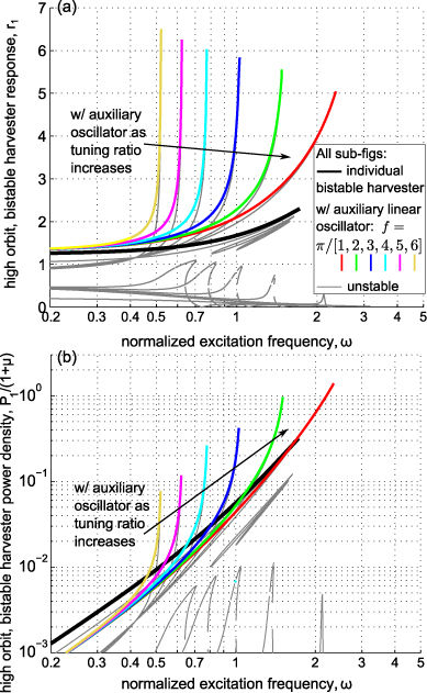
Figure 4. High-energy dynamics of the bistable harvester as the tuning ratio f changes. (a) Fundamental response amplitude r1 and (b) power density P1/(1 + μ).
Download figure:
Standard image High-resolution image4. Comparison of one-term and two-term solutions
The influence of induced superharmonic effects for power harvesting as a result of both greater excitation levels and the appendage linear oscillator was next considered. The two equations (52) and (53) were solved using the procedure described in section 2.3, allowing the nonlinear equation solver to perform refined searches at each frequency to determine all possible solutions proportional to the fundamental and third harmonic responses. The method is not a significant computational burden primarily because one may determine a reasonably accurate initial guess of the response magnitude for the solver once the one-term solution has been computed.
The equations were solved for the parameters p = 3,β = 0.1,μ = 1, and f = 1.67 while other constants remained the same as those employed in section 3. The excitation level p = 3 is increased by approximately an order of magnitude from section 3 since a greater excitation level is known to be one means of more readily inducing multi-harmonic nonlinear phenomena [20]. Figures 5 and 6 present the high-energy orbit bistable harvester response amplitude and output power, respectively, comparing the one-term and two-term model formulation results. We note that the amplitudes predicted by the two-term formulation represent the individual spectral contributions of the fundamental and superharmonic responses and would collectively make up the physical response amplitude, as defined in equation (33). At each excitation frequency, 50 long-time simulations are conducted of the governing equations (5) and (6), their fast Fourier transforms taken for the final half of the time series, the fundamental and order-3 superharmonic spectral lines are computed for each run, and then results from the 50 runs are averaged and presented as numerical validation data points. Across the full bandwidth considered, the inclusion of superharmonic terms in the harmonic balance solution formulation substantially alters the predictions as compared with the one-term results. For frequencies less than approximately ω ≈ 0.3, the two-term analysis predicts that several fundamental and superharmonic solution pairs may exist, although numerical simulation did not uncover the predicted higher magnitude superharmonic response branch in this bandwidth. The two-term harmonic balance solution predicts that one fundamental (superharmonic) response pair would decrease (increase) rapidly at a bifurcation around ω ≈ 0.3, and this trend is observed in direct simulation. In the bandwidth around ω ≈ 0.4–0.7, the two-term analytical predictions indicate that only one solution pair exists having rapidly decreasing and then increasing order-3 harmonic magnitude while the fundamental steadily increases in amplitude; the numerical simulations are in good quantitative agreement with this prediction.
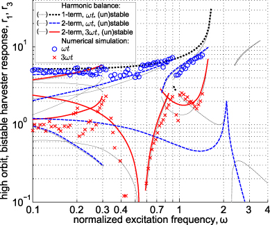
Figure 5. Comparison of numerically and analytically predicted high-energy orbit response amplitudes r1,3 with an appendage linear oscillator.
Download figure:
Standard image High-resolution image
Figure 6. Comparison of numerically and analytically predicted high-energy orbit electrical powers P1,3 with an appendage linear oscillator.
Download figure:
Standard image High-resolution imageA sudden reduction in the fundamental harmonic response amplitude is predicted by the two-term solution around ω ≈ 0.8, a feature verified by numerical simulation. The two-term formulation predicts that this reduction in fundamental response corresponds to a sudden increase in the order-3 superharmonic which is also observed in simulation. In the bandwidth around this drop in fundamental response near ω ≈ 0.8, two solution pairs are predicted by the two-term analysis which have similar magnitudes of superharmonic response but notably different amplitudes of the fundamental response. While a harmonic balance analysis does not indicate the likelihood of attaining one of several co-existing solution forms, the prediction of additional response pairs near ω ≈ 0.8 in figure 5 suggests that at least two distinct forms of organized interwell dynamics are possible. From approximately ω ≈ 1–1.4, the superharmonic response becomes substantial and the power density proportional to this response approaches a similar magnitude to that associated with the fundamental; the simulations quantitatively verify the two-term analytical formulation predictions which are quite distinct as compared to the one-term results.
Overall, the intricate responses observed via direct simulation are much more accurately captured by the two-term harmonic balance formulation as compared with the one-term approach. The analysis suggests that the influence of superharmonic response plays a critical role in the dispersion of the vibrational energy in the bistable harvester with appendage oscillator. This observation has important implications in an energy harvesting context given that superharmonic dynamics may be equally or more advantageous to utilize for power harvesting than those responses having frequency equal to the excitation.
5. Experimental validations
The previous analyses indicated key influences that the auxiliary linear oscillator would provide in enhancing the energy harvesting performance of the bistable system. Specifically, section 3.2 predicted that the tuning ratio f was a parameter capable of tailoring the bandwidth and rate of amplified response (figure 4). In section 4 the inducement of superharmonic dynamics was predicted to play a crucial role in concentrating energy (figures 5 and 6), providing new opportunities for power harvesting. Therefore, corresponding experiments are conducted to qualitatively verify these principal analytical findings.
5.1. Experiment setup description
A photograph of the test setup is shown in figure 7. A bistable device is constructed using an inertial mass connected to a translational slide bearing and pre-compressed spring (left of the figure). Two guiding rods are included in the design so as to eliminate the potential for bending or twisting of the compressed spring during snap through. A linear oscillator (right of the figure) on a separate slide bearing could be connected to the bistable mass via a removable linear spring. In this study, two linear coupling springs are employed such that the resulting tuning ratios are f1 ≈ 4 and f2 ≈ 2 given that the uncoupled bistable oscillator is observed to have a linear natural frequency of ω1/2π ≈ 4 Hz. The mass of the appended oscillator is such that μ ≈ 0.75. The system is mounted on an electrodynamic shaker platform (shaking horizontally left and right). The motion of the linear oscillator is isolated from the direct shaker motion. Accelerometers are mounted on the inertial masses while a potentiometer measures the shaker displacement; all measurements are in the horizontal left–right direction. In a similar spirit to the model formulation, we assume that the power generation is proportional to the response amplitude squared of the bistable oscillator given the inclusion of appropriate transduction mechanisms, for example a translational induction mechanism in the bistable oscillator slide bearing or rotational induction generators that constrain the pre-compressed spring.
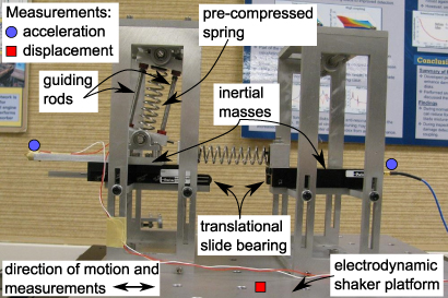
Figure 7. Photograph of the test setup.
Download figure:
Standard image High-resolution image5.2. Influence of the tuning ratio, f
In section 3.2 it is observed that the tuning ratio f may be tailored so as to control the bandwidth and rate of the amplified bistable energy harvester response as compared to the device without the auxiliary element. To validate the analytical predictions, tests are run using slow forward frequency sweeps from 2 Hz at a rate of 0.15 Hz s−1 with the bistable devices initially vibrating in continuous high-energy orbit. The frequency response function (frf) of the bistable oscillator inertial mass acceleration to the shaker input acceleration is evaluated with and without the appendage linear oscillator to serve as a normalized response magnitude metric.
Figure 8 plots the response with and without appendage linear oscillators having tuning ratios f1 and f2. The individual bistable device frf (black crosses) exhibits the anticipated trend of gradually increased amplitude towards the frequency at which interwell vibration is destabilized. Once the auxiliary linear element is added to the bistable device, as analytically predicted throughout this paper, the response amplitude (here, acceleration frf) is uniformly amplified below the linear oscillator natural frequencies. In these examples, the linear oscillator natural frequencies are approximately 16 Hz for f1 and 8 Hz for f2. As compared to the individual bistable oscillator frf, the addition of the appendage linear oscillator of tuning ratio f1 (red squares) amplifies the frf by approximately 80% at 4 Hz; when using the auxiliary oscillator of linkage with f2 (blue circles) 360% enhancement at 3.75 Hz is obtained. These findings are qualitatively in good agreement with those predicted in section 3.2 by the fundamental harmonic balance analysis, figure 4, and demonstrate the utility of the simplified one-term solution approach for this response regime.
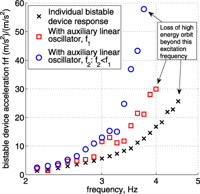
Figure 8. High-energy orbit bistable oscillator acceleration frf with and without an appendage linear oscillator.
Download figure:
Standard image High-resolution image5.3. Prevalence of superharmonic response
The analytical predictions of section 4 indicated that at certain frequencies near the point of high-energy orbit destabilization, the system with the appendage oscillator may exhibit two interwell vibration responses uniquely characterized by their proportion of fundamental and superharmonic vibration. The two responses are co-existent and the ultimate determination as to which is attained is dependent on the initial conditions. To evaluate this feature experimentally, we excite the bistable oscillator at 4 Hz with and without the auxiliary element of tuning ratio f1 ≈ 4 and monitor the steady-state responses.
Figures 9 and 10 respectively plot the acceleration autospectra and time series of the two co-existent forms of interwell vibration exhibited by the bistable oscillators with and without the appendage element. Figure 9 shows the response corresponding to continuous high-energy orbit having a predominant response frequency commensurate with the excitation. The system with auxiliary linear oscillator diffuses approximately one order of magnitude less vibrational energy to the order-1/3 subharmonic (at three times the excitation frequency) as compared with the individual bistable device. The spectral concentration of bistable harvester snap through energy is an advantageous result because harvesting circuitry should optimally switch interface connections at the frequency of greatest harvester response to maximize power flow to the storage element [28, 44, 45]. We find that at the driving frequency, the bistable device autospectrum with appendage oscillator is 48.7% greater than the individual bistable device response: 1016 (m s−2)2 Hz−1 as compared to 685.1 (m s−2)2 Hz−1, figure 9(a). Due to the linkage to the appendage oscillator, an additional spectral peak is observed at a frequency of approximately four times the excitation, which corresponds to the natural frequency of the add-on element; however, this peak is several orders of magnitude less than that measured at the driving frequency and does not detract from the overall advantage obtained via the system with auxiliary oscillator.

Figure 9. Continuous snap through dynamics due to excitation at 4 Hz. (a) Acceleration autospectra and (b) time series.
Download figure:
Standard image High-resolution image
Figure 10. Multi-harmonic interwell vibration due to excitation at 4 Hz. (a) Acceleration autospectra and (b) time series.
Download figure:
Standard image High-resolution image
When the excitation at 4 Hz is begun with different initial conditions, alternative steady-state vibrational responses are discovered, and these are presented in figure 10. In both cases, sub- and superharmonic responses of fraction- and integer-multiples of order-3 are apparent. However, the individual bistable oscillator exhibits a far more diffuse autospectrum typical of chaotic dynamics; the time series in figure 10(b) likewise reflects aperiodic vibration. In contrast, the system with auxiliary oscillator yields a substantially more concentrated multi-harmonic response, in fact concentrating more of the vibrational energy at 1/3 of the excitation frequency than at the drive frequency itself. The time series of the bistable oscillator having an add-on element in figure 10(b) demonstrates the more organized composition of the vibration. At 1/3 of the excitation frequency, the bistable device autospectrum with the auxiliary element is 49.6% greater than the maximum autospectral peak for the individual bistable device that occurs at the drive frequency itself: 1.328 (m s−2)2 Hz−1 as compared to 0.8338 (m s−2)2 Hz−1, figure 10(a).
These results suggest that a bistable energy harvester with appendage linear oscillator is less susceptible to non-ideal excitation conditions than the individual harvester because its vibrational response may become more concentrated to target multi-harmonic spectral components, which is more suitable for efficient power harvesting circuits [28, 44, 45]. This feature was suggested in the analytical predictions of figures 5 and 6 in terms of the multiple solution responses for the coupled system in the band near ω ≈ 0.8. In contrast, the individual bistable device may attain either periodic high-energy orbit or adverse aperiodic response less useful for power harvesting. The experimental results of figures 9 and 10 validate the trends of the analytical predictions and exemplify the robustness of the proposed design methodology.
6. Conclusions
This study analytically and experimentally evaluated the performance and robustness improvements obtained by appending a linear oscillator to a bistable energy harvester. The findings also represent an initial investigation of the steady-state high-energy responses of such a system within the general dynamics literature. It is found that uniform amplification of the harvester response magnitude and power is achieved with the add-on element at frequencies below the oscillator resonance as compared to an individual bistable harvester. This trend is validated with corresponding experiments including the influence of tailoring the amplification by means of the oscillator frequency ratio f. The mass ratio μ of the appendage element appears to govern the amplification of this enhancement while a practical explanation for its cause may be a form of positive feedback between the linear oscillator and the bistable harvester as the oscillator is effectively excited to resonance via the bistable device which serves a role similar to a base excitation source. Power density is likewise amplified for the harvester with auxiliary oscillator, but this enhancement specifically occurs in a bandwidth below and near to the attachment's resonance. Additional robustness improvements are obtained in the form of concentrated superharmonic response in the advent of non-ideal excitation conditions as compared to the individual bistable harvester which may exhibit adverse aperiodic response for the same excitation. This feature is correspondingly observed in the two-term analytical formulation by way of multiple solution pairs having unique proportions of fundamental and superharmonic responses. The present analytical formulation, validated qualitatively via experiments and quantitatively via direct simulation, provides an efficient means by which to predict steady-state energy harvesting performance improvements attained with the simple yet effective design approach of a linear oscillator appended to a bistable harvester.
Appendix.: Expressions from section 2.3