
Abstract
Today many applications require new effective approaches for energy delivery on demand. Supercapacitors are viewed as essential energy storage devices that can continuously provide quick energy. The performance of supercapacitors is mostly determined by electrode materials that can store energy via electrostatic charge accumulation. This study presents new sustainable cellulose-derived composite electrodes which consist of carbon nanofibrous (CNF) mats covered with vapor-grown carbon nanotubes (CNTs). The CNF/CNT electrodes have high electrical conductivity and surface area: the two most important features that are responsible for good electrochemical performance of supercapacitor electrodes. The results show that the composite electrodes have fairly high values of specific capacitance (101 F g−1 at 5 mV s−1), energy and power density (10.28 W h kg−1 and 1.99 kW kg−1, respectively, at 1 A g−1) and can retain excellent performance over at least 2000 cycles (96.6% retention). These results indicate that sustainable cellulose-derived composites can be extensively used in the future as supercapacitor electrodes.
Export citation and abstract BibTeX RIS
1. Introduction
One of the ways to fulfill the requirements of a future sustainable society is using new efficient technologies that can satisfy our growing needs and remain environmentally friendly at the same time. Today hazardous primary and secondary batteries with relatively short lifetimes are substantial contributors to a tremendous amount of landfill. This rising problem leads to the necessity of using long-lasting and, even more importantly, environmentally safe energy storage devices such as supercapacitors [1, 2].
Contemporary supercapacitors still need to be improved in terms of capacitance, energy density and cycling stability. The supercapacitor's performance is mostly influenced by its main constituents, electrodes, which are typically made of carbon nanomaterials [3]. Many different forms of carbon have been utilized as electrode materials for supercapacitors [4]. Among them carbon nanofibers (CNFs) with well-developed mesoporosity, high mechanical and electrochemical stability are seen as prospective materials for the electrostatic energy storage inherent to electrical double layer (EDL) capacitors. The mesoporous structure of CNFs allows a substantial uptake of an electrolyte solution with the subsequent unrestricted diffusion of electrolyte ions into electrode cavities, which is very important for the high power performance of a storage device [5, 6]. Moreover, nowadays CNFs can be produced in a convenient way through the carbonization of electrospun polymeric precursors. The resulting flexible CNF sheets have freestanding nature (they can be used without a polymeric binder) with a controlled fiber diameter below one micrometer [7, 8].
On the other hand, CNF materials derived from electrospun polymers have rather low specific surface areas (due to the fairly large diameter of fibers) and mediocre electrical conductivity (due to the amorphous carbon structure with many defects) [9, 10]. These flawed properties can be diminished by functionalization with much smaller and more conductive carbon nanotubes (CNTs). According to recent studies, there are three major techniques for making efficient CNF/CNT composite electrode materials for use in supercapacitors: (1) the addition of dispersed CNTs into polymeric solution prior to electrospinning followed by the carbonization of composite fibers [10–13]; (2) the addition of dispersed CNTs onto fibers after electrospinning followed by the carbonization of composite fibers [14]; (3) chemical vapor deposition (CVD) of CNTs on top of the carbonized electrospun fibers [15–17]. All of these suggested methods were successful in improving the electrochemical performance of CNF materials with the addition of CNTs (the highest shown values of specific capacitance were 417 F g−1 at 0.5 A g−1 [13] and 185 F g−1 at 0.625 A g−1 [15] for three- and two-electrode systems, respectively). Though CNF/CNT composite electrodes produced using the third method have slightly lower rate capability and cycling stability (possibly due to their complex hierarchical structure), their resistance is lower as well (this can be explained by the better contact between the electrode surfaces and collectors). Moreover, CVD is a highly adjustable technique in terms of the density and thickness of CNT deposition, and requires no complicated preparation of CNT dispersions.
Nevertheless, the abovementioned works are mostly concentrated on composites that consist of unsustainable components, whereas very promising composite electrodes derived from sustainable renewable resources have only recently has found their application in supercapacitors [11, 14, 18–20]. Despite their lack of high bulk conductivity, non-carbonized 'conductive' mats have exceptional mechanical properties and tailorability suitable for wearable electronics [18, 19], while carbonized cellulosic precursors result in highly conductive materials suitable for energy storage devices [11, 14, 20]. In this study, cellulose-derived freestanding hierarchical CNF/CNT composite materials with desirable properties for electrostatic energy storage were evaluated as electrodes with potential use for novel on-chip supercapacitors [21]. Owing to the continuously increasing demand on carbon nanomaterials, in the near future vast raw material resource such as cellulose should start replacing the currently used, non-renewable and globally detrimental coal tar pitch and synthetic polymers as precursors for the synthesis of carbons. Our study is envisioned to accelerate this process.
2. Experimental
2.1. Fabrication of composite electrodes
The composite CNF/CNT electrodes were produced via chemical vapor deposition of CNTs on top of cellulose-derived CNFs. Initially, CNF sheets were fabricated by executing the following three consecutive steps: cellulose acetate electrospinning (17 wt% solution of the polymer in 2:1 solvent ratio of acetone and dimethylacetamide), cellulose regeneration (in 0.1 M water solution of NaOH) and carbonization (in a quartz tube furnace with N2 flow by heating up to 800 °C with the heating rate of 5 °C min−1) according to [9]. Subsequently, CNTs were thermally grown on CNF substrates at 700 °C for 10 min using acetylene as a carbon source, 2 nm thick iron layer as a catalyst and hydrogen as a carrier gas (in AIXTRON Nanoinstruments Black Magic 2 inch machine). Finally, prior to electrochemical measurements, the CNF/CNT composites were dipped into a mixture with equal volumetric proportions of 1M nitric and sulphuric acids to remove catalytic particles, and thoroughly washed afterwards with DI water to avoid contamination with dissolved ions.
2.2. Material characterization
The morphology of the composite materials was observed using high resolution scanning electron microscopy (SEM) (Leo Ultra 55 FEG SEM, Zeiss) in a secondary electron mode at an acceleration voltage of 3 kV.
For transmission electron microscopy (TEM), as-grown CNF/CNT samples sandwiched between two Cu-grids (Athene G204, 400 mesh) were placed in a single tilt sample holder and further examined in a JEOL (JEM 2100) TEM equipped with a LaB6 cathode and a Gatan (SC1000 Orius) digital cyclic charge–discharge (CCD) camera. Imaging was done using an electron acceleration voltage of 80 kV, in order to stay below the threshold for knock-on damage and to minimize electron-beam induced damages in the CNTs [22].
The surface area of the materials was measured using the Brunauer–Emmett–Teller nitrogen adsorption method, and mesopore size distribution was quantified by the Barett–Joyner–Halenda method using an adsorption isotherm (TriStar 3000 V6.04 A surface area and pore analyzer). The samples were degassed under vacuum at 225 °C for 4 h prior to the measurements.
The x-ray photoelectron spectroscopy (XPS) was performed on a Quantum 2000 scanning ESCA microprobe (Physical Electronics) to assess the presence of catalyst residues in the samples. An Al Kα x-ray source (1486.6 eV) with a beam size of 100 μm was used. The area analyzed was about 400 × 500 µm2 with a depth of 4–5 nm. The results were evaluated using MultiPAK 6.1A software.
X-ray diffraction (XRD) analysis was made using a Philips X'Pert Materials Research Dif-fractometer with an x-ray tube with Cu anode (Kα radiation, λ = 1.541 84 Å) as a radiation generator at 45 kV and 40 mA. Phase analysis was carried out with X'Pert HighScore 3.0 (PANalytical BV).
Raman spectroscopy was implemented to evaluate the microstructure of vapor-grown CNTs. Raman spectra were obtained using a 638 nm laser source on a Horiba XploRA spectrometer equipped with an Olympus BX41 microscope. Spectra were analyzed with LabSpec software.
The electrical conductivity of the materials was evaluated using a four-point probe system (CMT-SR2000N, AIT). Five different measurement spots were taken for analysis of each sample.
2.3. Electrochemical analysis
Electrochemical performance was measured in a Swagelok supercapacitor cell consisting of a symmetrical two-electrode system with CNF-based carbon nanomaterials as working electrodes, electrospun cellulose as a separator, and 6 M aqueous solution of KOH as an electrolyte. The working electrodes and separators were cut to a circular area of 0.5 cm2 to fit current collectors. Before starting the measurements, the electrodes were immersed in the electrolyte solution for 24 h.
Electrochemical measurements were performed with Gamry Reference 3000 potentiostat/galvanostat/ZRA and data were analyzed with Gamry Echem Analyst. A voltage range between 0 and 1 V was used for CV (cyclic voltammetry) measurements at five different scan rates (5, 10, 20, 100 and 200 mV s−1), while GCD (galvanostatic charge–discharge) tests were performed at six different current densities (0.5, 1, 1.5, 2, 5 and 10 A g−1). EIS (electrochemical impedance spectroscopy) was completed at an open circuit potential with an AC amplitude of 5 mV over a frequency range from 100 kHz–10 mHz. Electrochemical stability tests were performed by CCD for 2000 cycles with a current density of 1 A g−1.
3. Results and discussion
3.1. Morphology and surface properties
Freestanding CNF mats with a thickness of 25–40 µm were obtained via carbonization of electrospun cellulosic precursors. The mats consist of fibers with 50–250 nm diameters. The continuous fibers are randomly oriented and have a smooth topography (figure 1, bottom right corner). The morphology of the composite material is rather different (figure 1, top left corner). After chemical vapor deposition, the bigger CNFs were densely covered with much smaller uniform CNTs (5–10 nm tube diameters), thus forming a hierarchical nanocomposite material. A straight boundary line between the pristine CNF region and the region with deposited CNTs validates the reliable space controllable deposition of iron catalytic particles.

Figure 1. SEM image of the interface between pristine CNF region (bottom right corner, magnified image as inset) and region after deposition of CNTs (top left corner, magnified image as inset).
Download figure:
Standard image High-resolution imageFigure 2(A) reveals slightly uneven growth of CNTs on different sides of the CNF, which could be due to the heterogeneous distribution of heat or catalytic particles within a CNF substrate during CNT growth. A closer look at the CNTs (figure 2(B)) exposes catalytic particles which are commonly seen inside the tip of the CNTs but occasionally also remote from the tip, still inside the tube walls but further towards the tube base. In such cases, the tip could sometimes be curled up, indicating that the direction of growth is less straight once a tube grows past a catalyst particle. The number of tube walls typically varied between three and eight, with rare occurrences of single- and double walled tubes (figure 2(C)). Measurements were taken in several different distances from the CNT base, both near the CNF on which they were grown, as well as close to the CNT tips, and the distribution of outer and inner diameters was found to be fairly homogeneous. The measurements revealed outer tube diameters do in the span of 5–10 nm and inner diameters di—3–5 nm, resulting in a normalized thickness  of 0.4–0.55. The range of tn is in the lower region of typical values for CVD-grown CNTs and considerably lower than for CNTs grown by arc-discharge (where typically tn is much larger than 0.5) [23].

Figure 2. TEM images of the vapor-grown CNTs on top of a CNF at different magnifications.
Download figure:
Standard image High-resolution imageFigure 3(A) shows a nitrogen adsorption isotherm and pore size distribution for the CNF/CNT material. The shape of the isotherm is characteristic for meso- and macro-porous (pores with a size range of 2–50 and >50 nm, respectively) materials without a developed microporous structure [24], which is in accordance with figures 1 and 2. Meso- and macro-porosity of the composite are very important for electrostatic energy storage as they provide sufficient access of electrolyte ions to the surface, support charge propagation and accumulation, and, as a result, increase the power capability of a supercapacitor [25]. Besides this, pore size distribution points to the presence of pores with a diameter below 10 nm, which makes a substantial contribution to the total surface area of the synthesized composites (table 1). Pores of this size should be attributed to the CNTs which are much smaller than the CNFs and thus have much higher specific surface area [14].
Table 1. Material properties of the composite material in comparison with the pure CNF material.
| Sample | Surface area (m2 g−1) | Carbon content (%) | Electrical conductivity (S cm−1) | Electrode capacitance (F g−1) |
Energy density (W h kg−1) |
Power density (kW kg−1) |
Capacitance retention (%) |
|---|---|---|---|---|---|---|---|
| CNF | 45 | 97.4 | 4.2 | 46.5 | 1.24 | 1.73 | 88.7 |
| CNF/CNT | 131 | 99.3 | 69.4 | 91.5 | 10.28 | 1.99 | 96.6 |
aMeasured at a scan rate of 10 mV s−1. bMeasured at a current density of 1 A g−1.
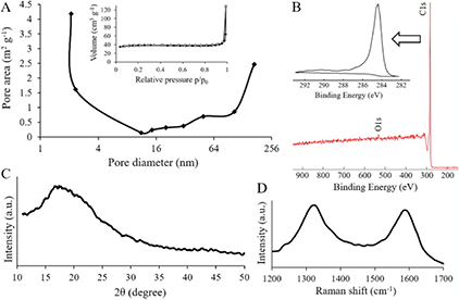
Figure 3. Surface analyses of the CNF/CNT material. (A) Nitrogen adsorption/desorption isotherms (inset) and pore size distribution (main image). (B) C1s XPS spectrum (inset) and survey scan (main image). (C) XRD pattern. (D) Raman spectrum.
Download figure:
Standard image High-resolution imageThe XPS analysis (figure 3(B)) confirmed that both the pure CNF material and the CNF/CNT composite almost completely consist of carbon with predominant C–C bonds (a peak at 284.5 eV). The pure CNFs contain slightly more oxygen which can be due to their more amorphous nature in comparison to the CNTs. It should lead to faster oxidation of CNFs when they are exposed to air.
The XRD analysis was used to evaluate the crystalline structure of the composite CNF/CNT material (figure 3(C). It is hard to differentiate a graphitic peak around 25°, which is usually attributed to CNTs [12], as it overlaps with a broad amorphous peak around 18° which is a characteristic peak for cellulose-derived carbons obtained after carbonization at temperatures below 3000 °C [24].
The Raman spectra (figure 3(D)) shows two broad bands at ~1320 cm−1 and ~1590 cm−1 that can be respectively assigned to amorphous sp2-bonded carbons with structural defects (D-band) and crystalline sp2-bonded carbons (G-band) [26]. ID/IG ratio for the composite material was calculated to estimate the level of disorder in the carbonaceous structure. This ratio is 1.07, which confirms the prevalence of an amorphous CNF part.
The conductivity values for the CNF/CNT composite are more than 15 times higher than for pure CNFs (table 1). This is due to the dense coverage of the CNF material with the highly conductive CNTs, which is enough to reach a critical electrical percolation threshold [27]. Effective combination of high electrical conductivity and appropriate morphology, i.e. the intrinsic properties of the synthesized CNF/CNT composite, is necessary for effective performance of carbon electrode materials used in supercapacitors [16].
3.2. Electrochemical performance
Various electrochemical measurements were used to evaluate the performance of the CNF/CNT composites as electrode materials in a supercapacitor device.
Figure 4(A) shows the dependence of capacitance on a scan rate for the composite CNF/CNT electrode. The CV curves have a moderately rectangular shape, which indicates an EDL capacitive behavior [28]. Distortion of the rectangular shape at higher scan rates (100–200 mV s−1) happens because of the lack of time for electrolyte ions to penetrate completely inside the electrode, whereas for lower scan rates (5–20 mV s−1) the ions reach the inner surface of the electrode providing higher accumulative charge [5]. For each electrode, the evaluation of the specific capacitance Cs was made according to equation (1),
where I(V) is the voltammetric current obtained from the integrated area of the CV curves, m is the total mass of carbon materials in two electrodes, dV/dt is the scan rate, and ΔV is the voltage range [10, 11]. The comparison of the CV curves of two different CNF-based nanostructured materials is presented in figure 4(B). The composite electrodes show about two times higher values of capacitance in comparison to the pure CNF electrodes. Addition of CNTs has a big influence on the performance of the CNF-based electrodes as CNTs significantly increase their surface area and electrical conductivity (table 1), which are key factors in making electrostatic charge accumulation process more efficient [14].
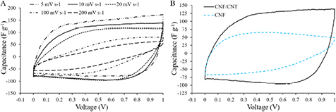
Figure 4. (A) CV curves of the CNF/CNT composite electrode at different scan rates. (B) CV curves of the composite and pure CNF electrodes at 10 mV s−1 scan rate.
Download figure:
Standard image High-resolution imageThe GCD curves show an almost triangular shape specifying EDL behavior as well (figure 5(A)). From the GCD test, power and energy density values were calculated using equations (2) and (3) respectively,
where Cs indicates the specific capacitance, ΔV is the potential difference excluding the IR drop and t is the discharge time [29]. From the GCD test power and energy density values were found to be reasonably high for the composite electrode materials. A fast current–voltage response proves that an electrode material has a high power density [24]. Figure 5(B) shows the dependence of the specific capacitance on current density. For the composite CNF/CNT electrode, at 0.5 A g−1 the capacitance is about 1.5 times higher than at 2 A g−1 and about 10 times higher than at 10 A g−1. At the higher current density many electrolyte ions cannot diffuse fast enough to an electrode surface and occupy available sites, which negatively effects accumulation of charges, i.e. decreases the capacitance [30].
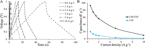
Figure 5. (A) GCD curves of the CNF/CNT electrode at different current densities. (B) Specific capacitance of the pure CNF and CNF/CNT electrodes as a function of the current density.
Download figure:
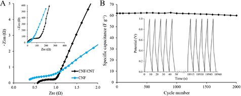
Standard image High-resolution imageAccording to EIS the equivalent series resistance (ESR) of a system is defined as the initial intercept of a plot with the X-axis in the high frequency region (figure 6(A)). ESR mostly comprises of bulk electrolyte resistance and interfacial resistance between an electrolyte and an electrode material. The composite electrode and the pure CNF electrode have low ESR values (0.57 and 0.38 Ω, respectively), which is good for effective electrochemical performance. A slightly lower value for the pure CNF material can be explained by its better wettability with the aqueous KOH electrolyte due to the higher amount of hydrophilic oxygen-containing groups (according to the XPS analysis). In contrast, charge transfer resistance, expressed as the intercept of a semicircle in the mid-higher frequency region, is lower for the CNF/CNT electrode compared to the pure CNF electrode (≈0.5 and ≈1 Ω, respectively), which verifies enhanced conductivity of the composite [12]. Moreover, the verticality of the Warburg line, the slope of the 45° segment of the curve in the low and medium frequency regions, validates sufficient pore accessibility for electrolyte ion diffusion [31].
Figure 6. (A) Full range spectra (inset) and high-frequency region (main image) of the Nyquist impedance plots of the composite and pure CNF electrodes. (B) Cycling stability of the CNF/CNT electrodes over 2000 cycles (main image); GCD curves for the first five and the last five cycles (inset).
Download figure:
Standard image High-resolution image
The long term exploitation of electrode materials is validated through their ability to withstand a large number of charge–discharge cycles and retain capacitance. The CNF/CNT electrodes retained 96.6% of the initial capacitance after 2000 cycles (figure 6(B)), which is a very good stability for an energy storage device such as a supercapacitor, as it has to deliver the harvested energy through quick charging and discharging many times [32]. High capacitance retention indicates excellent stability of the composite electrode material and confirms strong adhesion of vapor-grown CNTs to CNFs.
4. Conclusions
Freestanding cellulose-derived carbon nanocomposites were fabricated by chemical vapor deposition of CNTs on top of CNF mats. The resulting hierarchical carbon materials performed well as electrodes for supercapacitors. They showed fairly high capacitance (91.5 F g−1), indeed satisfactory energy and power density (≈4 W h kg−1 and ≈10 kW kg−1, respectively), and remained electrochemically stable over 2000 charge–discharge cycles. The composite materials have an advantageous combination of two properties that are essential for supercapacitor electrodes. Owing to the deposition of CNTs, the electrodes have high electrical conductivity, i.e. the electrode's ability to transfer charges, and increased surface area, i.e. the electrode's ability to uptake an electrolyte and accumulate charges. Overall, the hierarchical cellulose-derived CNF/CNT nanocomposites should be viewed as efficient sustainable electrode materials for electrostatic energy storage.
Acknowledgments
The Wallenberg Wood Science Center funded by Knut and Alice Wallenberg Foundation, the Vinnova CarPolCap and the EU Smart-MEMPHIS projects are greatly acknowledged for their financial support. We are also grateful for Anne Wendel's help with the XPS analysis.