
Abstract
Non-trivial arrangement of molecules within a molecular network complicates structure determination due to interdigitation, partial overlap, or stacking. We demonstrate that combined imaging and lateral manipulation with a scanning tunneling microscope resolves the intricate structure of a molecular network in two-dimensions in a straightforward manner. The network, formed by a monolayer of 5,10,15-tris(pentafluorophenyl)-corrole molecules on Ag(111), is manipulated for the first time with single-molecule precision. Our results reveal a shingle-like packing of partially overlapping corrole molecules. Density functional theory calculations support our findings.
Export citation and abstract BibTeX RIS

Content from this work may be used under the terms of the Creative Commons Attribution 3.0 licence. Any further distribution of this work must maintain attribution to the author(s) and the title of the work, journal citation and DOI.
1. Introduction
Ordered chains, islands, and layers of functional molecules, are crucial to diverse fields of research including (nano)engineered surfaces [1, 2], electronics [1], catalysis [3], sensorics [4], and cell adhesion [5]. The conformation, relative position and orientation of the individual molecules within these molecular networks and relative to the substrate atomic lattice determine their physico-chemical properties [2]. Commonly, the structure of such networks is characterized with methods based on the absorption and diffraction of x-rays and electrons, optical spectroscopy as well as scanning probe imaging. Interdigitation, partial overlap, or stacking of molecules can promote the formation of non-trivial (intricate) molecular arrangement within networks. Increased structural complexity of the individual molecules is believed to strongly affect the formation of intricate networks, as observed in previous studies of corrole derivatives [6–8]. Corroles [9, 10] are emerging as highly potent agents in catalysis, photochemical sensing, molecular electronics and biomedicine [11–13]. Corrole molecules, exhibiting low symmetry (C1) when adsorbed on metal substrates, facilitate non-trivial network structures, originating either from multiple conformational states [6, 8] or dissociation of axial ligands [7]. In such cases, a distinct structure determination of the molecular network turns out to be complicated—even when using scanning probe imaging methods that operate at sub-molecular resolution in real space. In comparison, free-base porphyrin, which is structurally similar but higher symmetric (C4), tends to form more trivial networks [2].
Here we show that by clever combination of imaging and manipulation the intricate structure of a non-trivial molecular network is resolved readily. We manipulate, for the first time, regular molecular networks formed by monolayer islands of molecules of the stable and archetypal 5,10,15-tris(pentafluorophenyl)-corrole (TpFPC, figure 1(a)). The manipulation is performed with the tip of a scanning tunneling microscope (STM) using lateral manipulation techniques [14–22]. This facilitates the unambiguous identification of different functional units in the network.

Figure 1. (a) Chemical structure (left) and stereochemical representation (right) of H3(TpFPC) molecules ( 796.5 amu). (b) Representative STM image of the rim of the TpFPC/Ag(111) monolayer molecular network (10 × 10 nm2,
  100 pA, z-scale is 0.2 nm); lattice parameters
 and γ; square (A) marks the image frame used to obtain the difference image labelled 'A minus B' in figure 2(a).
Download figure:
Standard image High-resolution image2. Methods
The Ag(111) substrate was prepared by cycles of Ar+ ion sputtering (600 eV) and thermal annealing at 720 K. TpFPC was sublimated at ultra-high vacuum conditions (base pressure  mbar) from a quartz crucible at 490 K onto the substrate held at 300 K and subsequently annealed at 360 K for 10 min. Samples were in situ transferred into the STM chamber. STM experiments were performed at 5 K, base pressure of
  mbar, employing electrochemically etched tungsten tips thermally deoxidized by flash-annealing above 1070 K. STM images were obtained at
  and 100 pA, and analyzed using the program WSxM [23]. The lateral manipulation of single molecules was performed in constant current mode (10 mV, 5 nA) with the tip moved at a speed of about 0.02 nm s−1 during manipulation. For manipulation, we move the tip over a selected molecule, switch to manipulation parameters (5 nA) and displace the STM tip along a defined path; after manipulation the parameters are restored for imaging (100 pA). This procedure yields a success rate of about 75%. We remark that a single molecule at a time is detached/displaced by our manipulation procedure; for detaching two or more molecules, we repeat the manipulation procedure for the respective number of single molecules. The final azimuthal orientation of each manipulated molecule was not controlled.
Total-energy density functional calculations were performed using the Vienna ab initio simulation package [24] including the projector-augmented wave method [25] for describing electron-ion interactions and the generalized gradient approximation (PW91 functional [26]) for modeling electron–electron exchange-correlation interactions. A semi-empirical scheme based on the London dispersion formula [27] was used to account for the influence of the ubiquitous dispersion interactions. The Kohn–Sham orbitals are expanded in a plane-wave basis with an energy cut-off of 400 eV. A Γ-centered 1 × 1 × 1 k-point mesh was employed to integrate the Brillouin zone. The Ag(111) substrate was modeled in slabs consisting of four atomic layers separated by a vacuum region of 3 nm. Atomic structure relaxations were performed with convergence criteria of 3 meV nm−1 and 10−5 eV for the forces and the total energies, respectively. Thereby the structural degrees of freedom of the adsorbate atoms and the uppermost two substrate layers were relaxed, whereas the atoms in the bottom two atomic layers were fixed at the ideal bulk positions. STM simulations were obtained via the Tersoff–Hamann model [28].
3. Results and discussion
Figure 1(b) shows a representative STM image of TpFPC/Ag(111) at a coverage of  monolayers. The molecules form islands of ordered monolayer molecular networks after annealing. The image shows the rim of the corrole network over a flat Ag(111) terrace. The dark region (top-left) corresponds to the pristine Ag(111) surface. The regular STM topographic pattern indicates the ordered network of corrole molecules. The pattern can be described by a two-dimensional regular lattice defined by an oblique primitive cell with lattice vectors
  and
and  (figure 1(b)). By varying the sample bias voltage within a range of ±2 V (not shown), we have determined a value of
  to be most suitable for topographic analysis, since the corrole network exhibits rich topographic structure. For the rest of the paper, we use this value for all displayed STM images. The bias dependence of STM images of the network will be presented elsewhere.
A detailed analysis of STM images of different islands of TpFPC/Ag(111) yields values of 
 and cell angle
  The given uncertainties represent the variance of values observed in different monolayer islands by STM, most possibly originating from slightly different structural phases with similar STM topographies. We have found the same cell dimensions in regions close and far from the network boundary (within experimental uncertainty). The vector
  is found to lie almost parallel to the Ag
  direction (figure 1(b)). Within the experimental uncertainty, the corrole network forms on Ag(111) a commensurable structure expressed by an integer valued transformation matrix
with substrate lattice vectors  and
and  forming an angle of
A complete characterization of the molecular network includes the lattice cell as well as the crystal basis. The latter describes the relative positions and orientations of individual molecules according to the lattice unit cell. In the present case, the protrusions in the STM images lack an obvious relation with the functional groups of individual molecules. This restricts an unambiguous determination of the crystal basis. We interpret this to be characteristic of non-trivial networks.
In order to overcome this restriction, we have displaced single corrole molecules laterally out of the molecular network by controlled STM manipulation (details: see methods). Figure 2(a) shows a representative example after displacing a single corrole molecule out of the rim of the network (same image frame as in figure 1(b)). The red arrow marks the manipulation path. The displaced corrole molecule exhibits an almost equilateral triangular-like topographic shape, as indicated by the dotted lines, with an overall height below 0.2 nm. The experimental topographic shape of the isolated corrole molecule is confirmed by our STM simulation (left inset of figure 2(a)). The corners of the triangular-like shape are attributed to the three pentafluorophenyl groups of TpFPC. The short molecular axis of the single corrole molecule is marked by a dashed line labeled 's'. Similar topographies have been reported by STM studies of single triphenyl-corrole molecules on Cu(111) [6, 7] and tris(pentafluorophenyl)-corrole Au(111) [8]. Based on the topographies exemplified in figure 2(a), we conclude that single TpFPC molecules remain intact after being displaced by the STM tip and, furthermore, that their macrocycles are oriented roughly parallel to the substrate surface.
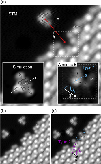
Figure 2. (a) STM image of TpFPC/Ag(111) molecular network after controlled displacement of a single molecule (same image frame as in figure 1(b); 10 × 10 nm2,  100 pA); red arrow marks the displacement path; lines are guides to the eye marking the triangular-like shape (dotted) and the short molecular axis (dashed, labeld 's') of the manipulated single TpFPC molecule. Left inset: simulated STM image of a single TpFPC molecule on Ag(111) at
  Right inset: experimental difference image (3 × 3 nm2) obtained by subtracting the topographic frame B from frame A of figure 1(b); the short molecular axis is oriented at an azimuthal angle
  relative to
  defining molecules of type 1. (b), (c) Same image frame as in (a) after displacement of two (b) and three (c) molecules revealing a second type of molecule with azimuthal angle
  denoted as type 2.
Download figure:
Standard image High-resolution imageIn a next step, we have applied a pixel-to-pixel subtraction of the STM image frames before and after manipulation. The right inset of figure 2(a) shows the topographic difference image obtained by subtracting the image frames labeled A and B in figures 1(b) and 2(a), respectively. Notice, that by obtaining the difference image labeled 'A minus B' we have gained a topographic portrait of the individual corrole molecule within the molecular network before displacement. The triangular-like shape characteristic of single molecules is well resolved in the difference image (compare left and right insets of figure 2(a)). With this result, we are capable of precisely identifying the positions and orientations of the individual corrole molecules within the network and relative to the substrate. The short molecular axis (s) of the imaged molecule forms an azimuthal angle of  with respect to
  (see right inset of figure 2(a)). We denote corrole molecules with such azimuthal orientation as 'type 1'. Additional protrusions, like the one labeled P in figure 2(a), are observed close to the manipulated molecules in difference images. We attribute them to fluorophenyl ligands of neighboring molecules, which are pulled more closely towards the substrate after manipulation (thus, appearing as protrusion in the difference image). This suggests that the manipulation procedure mechanically affects the immediate molecular surrounding of the manipulated molecule. We remark that observed protrusions P are consistent with the shingle-like molecular packing discussed as a result below. Based on consecutive manipulation steps of neighboring molecules, shown representatively in figures 2(b) and (c), we have identified a second type of molecule with a different azimuthal angle of
  (figure 2(c)). We denote molecules with such azimuthal orientation as 'type 2'.
Based on our STM results, we have obtained the crystal basis of the primitive lattice cell of the molecular network of TpFPC on Ag(111). Figure 3 shows the respective complete structure, including unit cell and crystal basis. The crystal basis consists of two molecules, labeled type 1 and type 2, as indicated by the structure models of corrole molecules overlaid on the STM image. Their lateral positions within the primitive unit cell have been determined based on the precise location of the pentafluorophenyl group in meso-position 10 (compare figure 1(a)), which is imaged as brightest protrusion for both types of molecules at  Accordingly, a vector
  measured between the two pentafluorophenyl units of the two molecules is obtained, defining the crystal basis as shown in figure 3. We found no evidence for a change of basis in regions near and far from the boundary of the network (within experimental uncertainty). We remark that, both, cell and basis have been determined solely by experiment, i.e., by imaging and manipulation with the STM. Notice the minimal distance between the two molecules obtained in figure 3—between macrocycle and pentafluorophenyl in meso-position 10. This points to a non-trivial partial overlap of the molecules, which is confirmed by our simulations discussed in the following.

Figure 3. Structure model of TpFPC/Ag(111) molecular network overlaid on STM topographic image. The parameters of the unit cell (
 and γ) and crystal basis (
 and
and  ) have been derived from STM imaging and manipulation experiments. The unit cell contains two molecules illustrated as wireframe models, labeled type 1 and type 2, obtained from structure calculations; short molecular axis is labeled 's'.
Download figure:
Standard image High-resolution imageIn order to verify our experimental results on the packing structure of the molecular network, we have performed density functional calculations. We have simulated different possibilities of arranging two TpFPC molecules within the two-dimensional unit cell defined by equation (1). We have tested different possible crystal basis configurations by varying the parameters 
 and
and  that determine the orientations of the molecules with respect to each other. In addition, we have relaxed the molecular geometries in order to account for different possible adsorption configurations as well as partial overlap between molecules. For each configuration, the adsorption energy has been calculated.
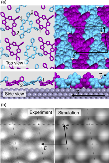
Figure 4(a) shows the most stable structure obtained by our calculations. The two molecules in the calculated structure have azimuthal orientations of  and
and  confirming our experimental results above. The simulation reveals a tilting of
  of the macrocycle of the molecules in the network with respect to the surface plane (see side-view). The direct bond between the A and D pyrroles of corrole (see figure 1(a)) is found to lie close to the surface, while the pentafluorophenyl in meso-position 10 is pushed away from the surface. In order to most clearly illustrate the particular tilted arrangement of molecules (shingle-like), the displayed structure of figure 4(a) has been azimuthally oriented with
  pointing horizontally on the page. The tilting enables a partial overlap between the pentafluorophenyl in meso-position 10 of type 1(2) corroles and pyrrole group D(A) of neighboring corroles, as marked by the dashed lines 1 in figure 4(a). The respective separation (1) of about 0.45 nm is slightly larger than in common π-stacked molecular networks [29]. A similar partial π-stacking-like arrangement is found between the pentafluorophenyls in meso-positions 5 and 15 of neighboring corrole molecules as marked by dashed lines 2 (respective separation of 0.5 nm). The partial overlap leads to a shingle-like packing of molecules along the
  direction. In comparison, TpFPC molecules of the monolayer have been proposed to exhibit a different side-tilted configuration on Au(111), where two pentafluorophenyls of corrole (at meso-positions 10 and 5(15)) lie closest to the surface [8]. Overlap of corrole molecules has not been found on Au(111), which might explain the
  % lower surface density compared to TpFPC/Ag(111). Details on the adsorption configuration on Ag(111) will be investigated in a forthcoming study.
Figure 4. (a) Calculated structure model of TpFPC/Ag(111) in top view (top) and side view (bottom) including unit cell vectors  and
and  The molecular packing is displayed in wireframe (left) and spacefill (right) styles. Dashed lines, labeled 1 and 2, mark π-stacking-like contacts between neighboring molecules. (b) Experimental (left) and simulated (right) STM image of TpFPC/Ag(111) with overlaid lattice (dotted line) and unit cell vectors
  and
and 
Download figure:
Standard image High-resolution image
Figure 4(b) compares the experimental (left) and calculated (right) STM images, indicating very good agreement. Notice that even the experimentally observed difference in intensity of the lobes attributed to the pentafluorophenyl in meso-position 10 of the two types of molecules (type 1 appears less bright than type 2 in experimental images) is well reproduced by the simulated STM. Our simulations confirm that the molecular packing of TpFPC/Ag(111) exhibits the characteristic properties of a non-trivial network, i.e. partial overlap, tilting and stacking of neighboring molecules.
In conclusion, we resolve the non-trivial geometrical structure of a single-layer molecular network of free-base corrole molecules on Ag(111) by combined STM imaging and manipulation. The network exhibits an intricate, shingle-like arrangement of corrole molecules with partial overlap due to π-stacking-like interactions, confirmed by simulation calculations. We propose that the presented manipulation method for structure resolving is, in general, applicable to a variety of different molecules forming intricate networks.
Acknowledgments
We kindly acknowledge the Austrian Science Found (FWF) and the German Research Foundation (DFG) for financial support of the projects D-A-CH I958 and GRK 1464. The calculations were done using grants of computer time from the Paderborn Center for Parallel Computing (PC2).