


Abstract
The present paper discusses the concept of measuring the process of sorption by means of the volumetric method, developed in such a way as to allow measurements performed under isobaric conditions. On the basis of the concept in question, a prototype of a sorption instrument was built: the manometric sorptomat. The paper provides a detailed description of the idea of the instrument, and of the way it works. In order to evaluate the usefulness of the device in sorption measurements carried out under laboratory conditions, comparative studies were conducted, during which the results of sorption measurements obtained with the developed instrument were compared with the results Mateusz obtained with a reference device. The objects of comparison were the sorption capacities of hard coal samples, calculated on the basis of the established courses of the methane sorption process. The results were regarded as compatible if the compared values fell within the range of the measurement uncertainty of the two devices. For the sake of the comparative studies, fifteen granular samples of hard coal—representing the 0.20–0.25 mm grain fraction and coming from various mines of the Upper Silesian Coal Basin—were used. After comparing the results obtained with the original manometric sorptomat with the results obtained with the gravimetric reference device, it was observed that the compatibility of measurements of sorption capacities was over 90%, based on the defined criterion of the measurement compatibility.
Export citation and abstract BibTeX RIS
1. Introduction
The availability of innovative measuring instruments that could be used in laboratory investigations of the solid–gas system is limited. The commercial sorption instruments—as precise and versatile as they happen to be—are extremely expensive, and thus unaffordable for a lot of laboratories. Other solutions applied in sorption measurements are based on methods developed several dozen years ago—these include typical volumetric instruments working under the conditions of changeable pressure.
The author is of the opinion that it is possible to construct measuring instruments for investigating the parameters of the solid-gas system that would combine high precision with user-friendliness and the low cost of production. At the Strata Mechanics Institute of the Polish Academy of Sciences, original concepts of measurement methods, as well as of devices for measuring the coal-gas system, are being developed. The prototype of the constructed manometric sorptomat attempts to fulfil the requirements specified above.
The aim of the present paper was:
- to design and construct a prototype of a volumetric measuring instrument for investigating the solid–gas system, working under isobaric conditions.
- to compare the sorption measurement results obtained with the constructed instrument with the results obtained with the reference device.
The constructed prototypical sorption instrument, called the manometric sorptomat, works on the basis of the volumetric method, developed in such a way as to allow measurements performed under isobaric conditions. The conducted comparative measurements involved recording the temporal changes of the amount of gas sorptively bonded in a granular sorbent sample at a given time. The reference instrument was the commercially available IGA-001 device, working on the basis of the gravimetric method.
The object of comparison were the sorption capacities of hard coal samples obtained under different methane pressure values. The compared results were regarded as compatible if the compared values fell within the range of the measurement uncertainty of the two devices—with the assumption that the uncertainties in question were acceptable.
2. The phenomenon of sorption in the solid-gas system
Sorption is a process that occurs in a lot of natural, biological and chemical systems. The surface sorption, occurring on the border of the two contacting phases and resulting in bonding molecules on the surface of the border between the phases, is known as adsorption. Depending on the type of the contacting phases, the sorption process can be analyzed from the perspective of the liquid–gas system, solid–gas system, solid–liquid system, or liquid–liquid system (Paderewski 1980), (Ościk 1983). The description of the phenomena related to the sorption process, included in the present paper, was narrowed down to the description of the phases of the solid–gas system, for which the constructed instrument was designed.
One characteristic feature of the surface of solids (adsorbents) is their ability to adsorb vapors and gases (adsorbates). This ability stems mostly from the fact that the forces inside a solid, ensuring the cohesiveness of the spatial structure, are only partially saturated on the surface of the border between the phases. This surface, called the surface proper, can attract molecules from the contacting phase (gaseous, liquid, or solid one). Depending on the type of interactions between the phases of the solid adsorbent and the molecules of the gaseous adsorbate, one can differentiate between the following (Kamieński 1980):
- physical adsorption—in which the attraction is based on weak intermolecular forces (the van der Waals forces) and occurs relatively fast,
- chemical adsorption (the so-called chemisorption)—in which the attraction is based on strong chemical interactions (electrons migrate from the adsorbent to the adsorbate) and occurs very slowly.
The phenomenon of adhesion (the dispersing forces in the physical adsorption), occurring between the adsorbate and the adsorbent surface, is responsible for the monolayer adsorption (figure 1) (Ceglarska-Stefańska and Zarębska 2005), (Majewska et al 2009). The consecutive adsorbate layers can be adsorbed on the already adsorbed molecules of the adsorbate mainly due to the cohesion forces (Nagaoka and Imae 2003), (Busch and Gensterblum 2011), (Gawor and Skoczylas 2014).

Figure 1. The monolayer adsorption versus the multilayer adsorption—a scheme.
Download figure:
Standard image High-resolution imageA gas molecule included in a certain volume has three degrees of freedom in terms of the translation movement (with the assumption that oscillation and rotation are neglected). Once a molecule has been adsorbed by a solid, the number of the degrees of freedom is reduced by at least one degree. The adsorbed particle can move over the surface of the solid—or become trapped in one spot, at the bottom of the interaction potential. Thus, the kinetics of the adsorption process can be understood as the speed with which a gas molecule moves from the 'free' state to the 'bonded' state. This process is also called the process of sorption on the free surface of a solid (Sevenster 1959).
3. The sorption instruments for investigating the solid-gas system
The measuring equipment for sorption studies finds its application in a lot of fields connected with geological (Dudzińska et al 2013), (Vishal et al 2013), (Olajossy 2014), (Walawska et al 2014), (Skoczylas and Wierzbicki 2014), (Skoczylas et al 2015), (Vishal and Singh 2015), (Vishal et al 2015), chemical (Pajdak et al 2015), biological, and other disciplines. The sorption instruments make it possible—among other things—to determine sorption capacities and sorption isotherms, or to measure the parameters that are indispensable in the process of calculating diffusion coefficients. The laboratory instruments for sorption measurements can be divided into three basic categories:
- volumetric instruments,
- gravimetric instruments,
- flow instruments.
In studies into measuring the sorption in the coal-gas system, the most frequent solutions are volumetric instruments (Ceglarska-Stefańska et al 2008), (Zarębska et al 2012), (Baran et al 2014). In the paper by (Pillalamarry et al 2011), the authors present the most typical volumetric constructional solution involving two containers of known volumes, connected by means of a valve (figure 2). In one of the containers, a sample with a sorbate is placed. The other container constitutes a depository of the gas to be sorbed. When the registration process begins, the valve between the containers is opened. The amount of the gas sorbed in the sample is established on the basis of the known values of the initial pressure (before the opening of the valve) and of the final pressure (after the containers were connected and the sorption processes ended).
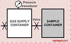
Figure 2. A typical volumetric sorption instrument—a concept scheme.
Download figure:
Standard image High-resolution imageSuch a solution is very simple in construction, and therefore easy to operate. However, it has several drawbacks. The value of gas pressure in both containers keeps falling up until the moment when a number of processes connected with the transportation and sorption of gas in a sample are finished. Due to this fact, it is impossible to analyze the kinetics of the sorption processes in progress. The end results of the measurement procedure can be checked only when the state of sorption equilibrium has been reached.
Another group of tools used in laboratory studies into sorption is constituted by gravimetric instruments (Benham and Ross 1989). Below, there are some commercially available examples of such devices:
- IsoSORP (Gravimetric Sorption Analyzer) by Rubotherm,
- DVS Advantage (Dynamic Vapor Sorption) by Surface Measurement Systems,
- IGA-001 (Intelligent Gravimetric Analyzer) by Hiden Isochema.
Gravimetric instruments record changes in the sample weight, related to sorption processes. The measurements are carried out under isobaric conditions. Among potential drawbacks of such instruments, one should mention their complicated construction, as well as the fact that, while establishing the end result, it is necessary to take the buoyant force into account. It should also be remembered that such instruments are very expensive, due to their complex structure. If a laboratory is to be equipped with this type of instruments, the amount of money to be spent becomes considerable.
The third category of instruments for sorption measurements—flow instruments—seldom finds its application in practice. The biggest problem is ensuring such a gas flow meter which would be very sensitive and, at the same time, characterized by a wide measuring range. Usually, ordinary flow meters are used in order to measure gas desorption from sorbents, and to establish permeability of a porous medium (Skoczylas 2015). The construction and tests of such a device were discussed by (Topolnicki et al 2009). The creators of the instrument decided to equip it with a multi-range flow meter to increase its measuring range.
One of the main objectives of the present thesis is to provide new metrological solutions in the field of studies into sorption in the solid-gas system. Innovative sorption devices have to be characterized by both high measurement precision and user-friendliness, as well as a low cost of production. When the construction of the discussed sorption instrument was already underway, it was decided that the requirements in question may be met only after the volumetric methods had been perfected. The constructed prototype of a manometric sorptomat uses the volumetric method—but, contrary to other typical tools from this group, the measurement is possible under both isobaric and isothermal conditions. The most important characteristics of the constructed instrument are: the simplicity of construction and service, and low production costs.
4. The measuring equipment
As part of the research presented in this paper, comparative studies into sorption of gases in hard coal samples were conducted. Two measuring instruments were used:
- the original instrument presented by the author—the manometric sorptomat,
- the commercial reference instrument—IGA-001.
The studies involved comparing the results obtained by means of the original instrument with the results generated by the commercially available gravimetric sorption analyzer IGA-001, which served as a reference instrument.
4.1. The original instrument—the manometric sorptomat
The manometric sorptomat is an improved version of a two-chamber volumetric instrument for sorption analysis. It was designed and constructed at the Strata Mechanics Research Institute of the Polish Academy of Sciences. The unique characteristics of the sorptomat were specified in a patent application filed with the Polish Patent Office. Additionally, the pressure regulator (Kudasik et al 2010) used in the manometric sorptomat was noticed during the 2013 MACAU International Innovation & Invention Expo and awarded a prize. In 2014, the creators of the pressure regulator obtained a diploma of the Polish Ministry of Science and Higher Education.
4.1.1. The functioning of the instrument.
The manometric sorptomat is composed of three containers connected with each other (see the scheme in figure 3). These are:
- The gas supply container
 of the volume , equipped with the pressure transducer . Inside the container, there is a supply of a gaseous sorbate, which—as the process of the sorption accumulation progresses—is directed into the two remaining containers via the solenoid valve . The changes in the pressure in the container are the measure of the amount of the sorptively bonded gas;
 - The gas buffer container equipped with the pressure transducer . The readings of the transducer make it possible to stabilize the pressure of the gaseous sorbate;
- The sample container . During the measurement, the container is connected with the gas buffer container by means of the valve , which ensures the isobaric conditions of the sorption process.


Figure 3. The concept of functioning of the original volumetric instrument—the manometric sorptomat.
Download figure:
Standard image High-resolution imageThe amount of the sorptively bonded gas is the result of the balance of the content of the three containers. The amount of gas included in a container is determined on the basis of the pressure values  ,
,  , temperature
  and the container volumes
  ,
,  and
and  .
.
4.1.2. The structure of the instrument.
The containers and the main body of the manometric sorptomat were made of aluminum. During calculations, it is necessary to take into account the volumes of particular containers. These were determined by means of the volumetric method, and are as follows:
- the volume of the gas supply container ,
- the volume of the gas buffer container ,
- the volume of the sample container .


4.1.3. The sample used in measurements.
A sample of the sorbent investigated by means of the manometric sorptomat is placed inside the sample container. The sorbent from which the sample is extracted can be coal core, briquette, or granular material. For the sake of the research discussed in this paper, granular coal samples were used (the 0.20–0.25 mm grain fraction). The average mass of the granular coal samples to be investigated with the manometric sorptomat was ca. 50 g.
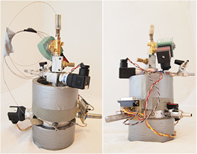
Figure 4. The manometric sorptomat—front view and rear view.
Download figure:
Standard image High-resolution image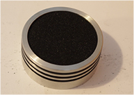
Figure 5. A granular coal sample placed inside the sample container of the manometric sorptomat.
Download figure:
Standard image High-resolution image4.1.4. The control system.
The amount of the gas sorptively bonded in a sample is determined by the balance of gas in the containers of the manometric sorptomat. This requires recording the changes in the pressures  ,
,  , as well as the temperature of the measurement
  . Additionally, it is necessary to simultaneously stabilize the pressure
  and the temperature
  during the measurement process. This is achieved due to the control system composed of the transducer card Advantech USB-4716 and the software DasyLab (see figure 6).
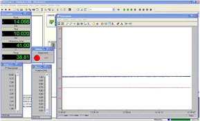
Figure 6. The main window of the DasyLab software, controlling the functioning of the manometric sorptomat.
Download figure:
Standard image High-resolution image4.1.5. The system for stabilizing the pressure.
Measurements with the manometric sorptomat are conducted under the constant pressure of the gaseous sorbate  , which falls within the range of 0–16 bar.
During the measurement, the gas pressure is stabilized in the connected containers  and
and  (figure 3). The gas flows from the container
  to the container
  via the solenoid valve
  and the damping capillary
  . The solenoid valve
  is controlled with a two-state regulator, created in the DasyLab system. The inlet of the regulator receives a signal from the pressure transducer
  , on the basis of which the regulator decides whether it is necessary to open or close the solenoid valve
  . The opening of the solenoid valve results in a sharp increase in the pressure
  , which compensates the loss of gas caused by the sorption process. Figure 7 presents example changes in the gas pressure
  , caused by sorption and the cyclical opening of the solenoid valve
  , as well as the sharp changes in the pressure value
  , caused by the flow of gas from the gas supply container
  into the connected containers
  and
and  .
.

Figure 7. An example fragment of the course of changes of the stabilized gas pressure  , together with the corresponding changes in the pressure
  , during the measurement of the sorption process carried out with the manometric sorptomat.
Download figure:
Standard image High-resolution imageDuring the process of gas sorption in the sample, the solenoid valve  is opened quasi-periodically, with the period gradually extended—until the state of sorption equilibrium is reached. The gas buffer container
  and the damping capillary
  are to level any sudden changes in the pressure
  , caused by the opening of the solenoid valve. The dimensions of the damping capillary
  (the internal diameter—0.21 mm) and the volume of the gas buffer container play a significant role in the process of stabilizing the gas pressure
  . The accuracy of the process of stabilizng the gas pressure
  by the constructed manometric sorptomat is ca. ±0.03 bar (figure 7).
4.1.6. The system for stabilizing the temperature.
The sorption studies, conducted by means of the manometric sorptomat, are carried out under isothermal conditions since the sorption capacity depends also on temperature (Skoczylas et al 2013), (Wierzbicki 2013). During the measurement, the temperature is maintained at a constant level, regulated within the range of 293–313 K. Bifilar winding, wound around the cylindrical casing of the sorptomat, serves as a thermometer. Another winding, electrically isolated from the thermometer, serves as a heater. Due to this solution, the readings of the temperature are averaged across the surface of the instrument. In a similar way, the stream of heat led to the sorptomat is averaged. The external heating winding is secured with thermal insulation in the form of thermal foam (figure 4).
The readings of the thermometer are transmitted to the inlet of the follow-up regulator, which decides about the power supplied by the heater. During the five-hour test of temperature stabilization, the stabilization accuracy was ±0.03 K (figure 8).

Figure 8. A sample fragment of the changes in the stabilized temperature during the measurement of the sorption process performed with the manometric sorptomat.
Download figure:
Standard image High-resolution image4.1.7. The balance of gas and measurement uncertainty.
Before the experiment begins, in the gas supply container  there is the starting pressure
  , and in the gas buffer container—the pressure
  , under which the sorption process will occur. In the container
  , which contains the sample, there is a void. After the valve
  is opened, gas flows into the container
  . At the same time, the solenoid valve
  is opened, which initiates the flow of gas into the gas buffer container
  . The solenoid valve remains open until the moment in which the pressure in the connected containers
  and
and  reaches the original value
  . The solenoid valve
  is opened in an impulse-like manner, supplying a portion of gas to the connected containers
  and
and  . As a result, the sorption occurs under the pressure
  , which changes within the range ±0.03 bar (figure 7). The amount of the absorbed gas is determined on the basis of the current balance, from the following formula:
where:
- —is sorption determined with the manometric sorptomat,
- —is the starting pressure in the gas supply container ,
- —is the instantaneous pressure in the gas supply container ,
- —is the instantaneous pressure in the gas buffer container ,
- —are the volumes of the containers , i and of the sample,
- —is the mass of the sample,
- —is the gas compressibility coefficient, which is also (among other things) the function of its critical pressure and critical temperature,
- —is the temperature,
- —is the universal gas constant,
- —is the molar volume of gas under normal conditions.
![${{a}^{\text{SM}}}\left[\frac{\text{c}{{\text{m}}^{3}}}{g}\right]~$](https://content.cld.iop.org/journals/0957-0233/27/3/035903/revision1/mstaa106fieqn068.gif)
![$~p_{A}^{0}\left[\text{Pa}\right]$](https://content.cld.iop.org/journals/0957-0233/27/3/035903/revision1/mstaa106fieqn069.gif)

![${{p}_{A}}(t)\left[\text{Pa}\right]$](https://content.cld.iop.org/journals/0957-0233/27/3/035903/revision1/mstaa106fieqn071.gif)

![${{p}_{B}}(t)\left[\text{Pa}\right]$](https://content.cld.iop.org/journals/0957-0233/27/3/035903/revision1/mstaa106fieqn073.gif)

![${{V}_{A}}\left[{{\text{m}}^{3}}\right],{{V}_{B}}\left[{{\text{m}}^{3}}\right],{{V}_{C}}\left[{{\text{m}}^{3}}\right],~{{V}_{S}}\left[{{\text{m}}^{3}}\right]$](https://content.cld.iop.org/journals/0957-0233/27/3/035903/revision1/mstaa106fieqn075.gif)


![$m\left[\text{g}\right]$](https://content.cld.iop.org/journals/0957-0233/27/3/035903/revision1/mstaa106fieqn079.gif)
![$z~[-]$](https://content.cld.iop.org/journals/0957-0233/27/3/035903/revision1/mstaa106fieqn080.gif)
![$T\left[\text{K}\right]$](https://content.cld.iop.org/journals/0957-0233/27/3/035903/revision1/mstaa106fieqn081.gif)
![$R\left[\frac{J}{\text{mol}\centerdot K}\right]$](https://content.cld.iop.org/journals/0957-0233/27/3/035903/revision1/mstaa106fieqn082.gif)
![${{V}_{m}}\left[\frac{\text{c}{{\text{m}}^{3}}}{\text{mol}}\right]$](https://content.cld.iop.org/journals/0957-0233/27/3/035903/revision1/mstaa106fieqn083.gif)
Measuring sorption with the manometric sorptomat is an indirect type of measurement. Calculating the measurement uncertainty of the manometric sorptomat is related to the complex uncertainty calculation. On the basis of the measurement uncertainties of the directly measured quantities in the equation (1), one can determine the uncertainty of the sorption measurement performed with the manometric sorptomat. This involves the application of the law of the propagation of uncertainty.
4.2. The reference instrument—IGA-001
The IGA-001 (intelligent gravimetric analyser) instrument by Hiden Isochema is a device that can be used to measure sorption by means of the gravimetric method (Benham and Ross 1989). The IGA-001 instrument (figure 9) is an advanced tool which makes it possible to perform fully automated sorption measurements under both isobaric and isothermal conditions.
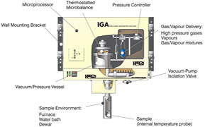
Figure 9. The structure of the IGA-001 instrument—a schematic representation (www.hidenisochema.com).
Download figure:
Standard image High-resolution imageThe study involving the IGA-001 system consists in tracking the changes in the mass of a sample caused by sorption/desorption of gas. These measurements are conducted under the conditions of constant gas pressure, regulated within the range of 0–20 bar, and under constant temperature, regulated within the range of 273–353 K. These ranges can be modified by developing the equipment itself. The IGA-001 instrument makes it possible to carry out fully automated research, programming the whole measurement sequence. It also makes it possible to determine the sorption isotherms of vapors and gases, on any type of sorbent, and to analyze the kinetics of sorption and desorption. Additionally, the IGA-001 instrument enables determination of the surface proper of the sorbent, its porosity and the distribution of the pore size, as well as absorption studies. The measuring capacities of IGA-001 are vast—in the discussed research, the instrument was used to determine sorption capacities.

Figure 10. The IGA-001 gravimetric instrument—a photograph.
Download figure:
Standard image High-resolution imageIn IGA-001, the direct parameter representing the measure of the sorption of gas in sample is the change in the mass of the sample, caused by sorption processes. The sample subjected to investigations is placed in the measurement chamber (figure 9), with specified measurement conditions (pressure and temperature). The sample is put on a platter (figure 11), suspended from a high-precision microscales. The microscales are controlled with a microprocessor system. The changes in the mass of the sample are registered continuously as a function of time, due to which it is possible to analyze the kinetics of the sorption processes under specified measurement conditions.

Figure 11. A platter with a sample, the IGA-001 instrument.
Download figure:
Standard image High-resolution imageThe direct results of the studies carried out with the IGA-001 instrument are the recorded changes of the sample mass, temperature, and pressure around the sample. The amount of gas sorptively bonded in a particular period of time results from the increase/decrease of weight recorded by the scales, and can be determined on the basis of the following formula:

where:
- —is the sorption determined with the IGA-001 instrument,
- —is the instantaneous and the original mass of the sample,
- —is the molar mass of gas,
- —is the correction compensating the buoyant force,
- —is the molar volume of gas,
- —is the gas compressibility coefficient,
- —is the sample density.
![${{a}^{\text{IGA}}}\left[\frac{\text{mol}}{g}\right],\left[\frac{\text{c}{{\text{m}}^{3}}}{g}\right]$](https://content.cld.iop.org/journals/0957-0233/27/3/035903/revision1/mstaa106fieqn084.gif)
![$m(t)[g],~{{m}_{0}}~[g]$](https://content.cld.iop.org/journals/0957-0233/27/3/035903/revision1/mstaa106fieqn085.gif)
![$M\left[\frac{g}{\text{mol}}\right]$](https://content.cld.iop.org/journals/0957-0233/27/3/035903/revision1/mstaa106fieqn086.gif)
![${{F}_{W}}[g]=\frac{m(t)\centerdot p\centerdot {{M}_{CH4}}}{{{\rho}_{s}}\centerdot z\centerdot R\centerdot T}\centerdot {{10}^{-6}}$](https://content.cld.iop.org/journals/0957-0233/27/3/035903/revision1/mstaa106fieqn087.gif)
![${{V}_{m}}\left[\frac{\text{c}{{\text{m}}^{3}}}{\text{mol}}\right]$](https://content.cld.iop.org/journals/0957-0233/27/3/035903/revision1/mstaa106fieqn088.gif)
![$z(T)~[-]$](https://content.cld.iop.org/journals/0957-0233/27/3/035903/revision1/mstaa106fieqn089.gif)
![${{\rho}_{s}}\left[\frac{g}{\text{c}{{\text{m}}^{3}}}\right]$](https://content.cld.iop.org/journals/0957-0233/27/3/035903/revision1/mstaa106fieqn090.gif)
The process of measuring sorption by means of the IGA-001 instrument is burdened with resultant uncertainty, stemming mostly from the precision of the microscales and the uncertainty of the correction compensating the buoyant force.
5. The research material and the measurement procedure
Since bituminous coal is a porous medium distinguished by good sorption properties (Bukowska et al 2012), (Baran et al 2015) fifteen granular coal samples were used in the comparative sorption studies. The samples were obtained from various mines of the Upper Silesian Coal Basin in Poland:
- the 'Borynia-Zofiówka' hard coal mine,
- the 'Brzeszcze' hard coal mine,
- the 'Pniówek' hard coal mine,
- the 'Budryk' hard coal mine.
The specification of both measuring instruments allows the use of various masses of coal material in measurements. For the sake of studies conducted with IGA-001, samples of the mass of ca. 0.5 g were used. For the sake of measurements conducted with the manometric sorptomat, samples of the mass of ca. 50 g were used. The properties of the samples destined for comparative studies were presented in table 1.
Table 1. Coal samples used in comparative sorption studies conducted with two measuring instruments.
| Sample no. | Sample mass [g] | Ash content [%] | Moisture content [%] | Volatile matter content [%] | |
|---|---|---|---|---|---|
| Manometric sorptomat | IGA-001 | ||||
| 172 | 48.9 | 0.448 | 2.38 | 1.58 | 24.31 |
| 174 | 46.7 | 0.498 | 8.34 | 1.17 | 20.56 |
| 175 | 51.0 | 0.437 | 1.55 | 5.22 | 24.42 |
| 178 | 40.1 | 0.470 | 1.25 | 3.35 | 31.47 |
| 182 | 51.7 | 0.450 | 5.29 | 1.33 | 36.40 |
| 183 | 52.4 | 0.465 | 12.56 | 1.42 | 28.43 |
| 188 | 50.1 | 0.457 | 2.50 | 1.11 | 26.42 |
| 198 | 53.8 | 0.481 | 10.14 | 1.22 | 23.52 |
| 201 | 52.6 | 0.450 | 9.63 | 1.28 | 25.75 |
| 202 | 49.1 | 0.442 | 3.38 | 1.27 | 30.78 |
| 203 | 53.5 | 0.453 | 7.28 | 1.29 | 27.97 |
| 205 | 49.5 | 0.443 | 2.64 | 1.17 | 29.12 |
| 206 | 52.6 | 0.451 | 3.13 | 1.09 | 27.50 |
| 221 | 32.9 | 0.474 | 1.90 | 1.24 | 30.75 |
| 222 | 49.4 | 0.463 | 3.61 | 1.52 | 27.23 |
The selection of the grain fraction of the samples destined for studies was a compromise between the predicted time of reaching the sorption equilibrium (ca. 1 d) and the measuring capacities of the two instruments. Given the wide scope of the planned investigations, the criterion of the duration of a single measurement was of vital importance. The 0.20–0.25 grain fraction was chosen, which is a fraction commonly used in the sorption studies conducted at the Micrometrics Laboratory of the Strata Mechanics Research Institute, commissioned by hard coal mining facilities.
All the measurements were conducted with methane used as the sorbing gas. The necessary condition for carrying out comparative studies is ensuring repeatability—both during the preparation of samples and during the experiments. The measurement procedure repeated during each measurement, for each investigated sample, involved the three consecutive stages:
- I.Preparing the coal sample for measurement—by sieving the proper grain fraction of the material destined for studies. The sieved material was divided into two portions, whose mass was, respectively, ca. 0.5 g and 50 g. The first portion was put on the platter of the sorption microscales of the IGA-001 instrument, the other one was placed inside the sample container of the manometric sorptomat;
- II.Outgassing the samples—carried out by means of vacuum pumps connected to the research equipment. The procedure, performed under isothermal conditions, lasted 24 h in each case. The rotating oil pump, used with the manometric sorptomat, made it possible to achieve the vacuum of ca. 10−5 bar, after 24 h of pumping. The turbomolecular pump, used with the IGA-001 gravimetric instrument, ensured the vacuum of ca. 10−9 bar;
- III.Saturating the sample with methane—under specific pressure and temperature, it lasted 24 h.
The values of the pressure of methane saturation, as well as the values of the measurement temperature, are shown in table 2.
Table 2. The conditions of sorption measurements conducted with the two measuring instruments.
| Sample no. | Number of measurement repetitions [−] | Saturation pressure values [bar] | Measurement temperatures [K] |
|---|---|---|---|
| 172 | 1 | 1 → 4 → 10 | 308 |
| 174 | 1 | 1 | 308 |
| 175 | 1 | 1 | 298 |
| 178 | 1 | 1 → 3 → 10 | 308 |
| 182 | 1 | 1 → 5 → 10 | 313 |
| 183 | 1 | 1 | 313 |
| 188 | 1 | 1 → 8 | 298 |
| 198 | 3 | 1 → 10 | 298 |
| 201 | 1 | 1 → 3 → 10 | 298 |
| 202 | 3 | 1 → 3 → 10 | 313 |
| 203 | 1 | 1 | 298 |
| 205 | 3 | 1 → 3 → 10 | 313 |
| 206 | 1 | 1 → 3 → 10 | 313 |
| 221 | 3 | 1 → 3 → 10 | 313 |
| 222 | 1 | 1 | 298 |
The purpose of the studies was to compare the results of measurements performed under the same conditions, with various measuring instruments. The analysis of the results involved:
- evaluating the measurement uncertainties on the basis of the precision of the applied measuring instruments,
- evaluating the compatibility of the results of sorption measurements performed with the two instruments, with the measurement uncertainty factor taken into account.
According to the specified measurement procedure, each measurement—under specific pressure conditions—lasted 24 h. The objects of comparison were the sorption capacities obtained in the 24th h of the measurement.
6. The results of the comparative sorption studies
Figure 12 presents the courses of changes of methane sorption as a function of time, determined for six randomly selected samples numbered 178, 182, 188, 201, 203 and 222, with the manometric sorptomat and the IGA-001 instrument. The solid lines in the graphs correspond to the results determined from the formulas (1) and (2), and the dotted lines take into account the measurement uncertainty of particular instruments.
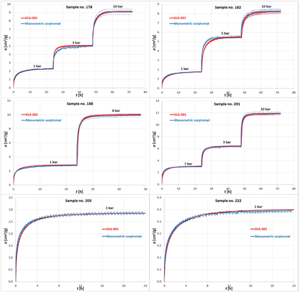
Figure 12. The course of changes in the sorption process, together with the measurement uncertainties, recorded by the manometric sorptomat and the IGA-001 instrument, for samples no. 178, 182, 188, 201, 203 and 222.
Download figure:
Standard image High-resolution imageTable 3 compares the obtained results of sorption capacities, together with their uncertainties, for all the samples investigated with the IGA-001 instrument and the manometric sorptomat. In the consecutive columns of the table, the following information was included:
- 1.The number of a sample,
- 2.—the pressure of the measurement,
- 3.—the sorption capacity determined from the formula (2), on the basis of the course registered with the IGA-001 instrument,
- 4.—the uncertainty of the sorption capacity measurement performed with the IGA-001 instrument,
- 5–6.—the lower and upper limit of the range of measurement uncertainty concerning the result of the sorption capacity measurement performed with the IGA-001 instrument,
- 7.—the sorption capacity determined from the formula (1), on the basis of the course registered with the manometric sorptomat,
- 8.—the uncertainty of the sorption capacity measurement performed with the manometric sorptomat,
- 9–10.—the lower and upper limit of the range of measurement uncertainty concerning the result of the sorption capacity measurement performed with the manometric sorptomat,
- 11.—the relative difference of the sorption capacity measurement, obtained with the manometric sorptomat, with reference to the readings of the IGA-001 instrument,
- 12–13.—the common range of the measurement uncertainty concerning the result of the sorption capacity measurement performed with the IGA-001 instrument and with the manometric sorptomat, understood as a result of the conjunction of the range of the upper and lower limit of measurement uncertainties:
- 14.The result (Y—compatible, N—incompatible)—determines the compatibility/incompability of the result of the sorption capacity measurement performed with the manometric sorptomat and the IGA-001 gravimetric instrument. The compatibility was determined on the basis of the existence of a common measurement uncertainty range concerning the result of sorption capacity measurement. The result was classified as incompatible if there was no common part of the measurement uncertainty range in columns 12 and 13. Otherwise, the result was classified as compatible.
![$p~\left[\text{bar}\right]$](https://content.cld.iop.org/journals/0957-0233/27/3/035903/revision1/mstaa106fieqn102.gif)
![${{a}^{\text{IGA}}}\left[\frac{\text{c}{{\text{m}}^{3}}}{{{g}_{\text{CSW}}}}\right]$](https://content.cld.iop.org/journals/0957-0233/27/3/035903/revision1/mstaa106fieqn103.gif)
![$\text{u}\left({{a}^{\text{IGA}}}\right)\left[\frac{\text{c}{{\text{m}}^{3}}}{{{g}_{\text{CSW}}}}\right]$](https://content.cld.iop.org/journals/0957-0233/27/3/035903/revision1/mstaa106fieqn104.gif)
![${{a}^{\text{IGA}}}-u\left({{a}^{\text{IGA}}}\right)\left[\frac{\text{c}{{\text{m}}^{3}}}{{{g}_{\text{CSW}}}}\right];~{{a}^{\text{IGA}}}+u\left({{a}^{\text{IGA}}}\right)\left[\frac{\text{c}{{\text{m}}^{3}}}{{{g}_{\text{CSW}}}}\right]$](https://content.cld.iop.org/journals/0957-0233/27/3/035903/revision1/mstaa106fieqn105.gif)
![${{a}^{\text{SM}}}\left[\frac{\text{c}{{\text{m}}^{3}}}{{{g}_{\text{CSW}}}}\right]$](https://content.cld.iop.org/journals/0957-0233/27/3/035903/revision1/mstaa106fieqn106.gif)
![$u\left({{a}^{\text{SM}}}\right)\left[\frac{\text{c}{{\text{m}}^{3}}}{{{g}_{\text{CSW}}}}\right]$](https://content.cld.iop.org/journals/0957-0233/27/3/035903/revision1/mstaa106fieqn107.gif)
![${{a}^{\text{SM}}}-u\left({{a}^{\text{SM}}}\right)\left[\frac{\text{c}{{\text{m}}^{3}}}{{{g}_{\text{CSW}}}}\right];~{{a}^{\text{SM}}}+u\left({{a}^{\text{SM}}}\right)\left[\frac{\text{c}{{\text{m}}^{3}}}{{{g}_{\text{CSW}}}}\right]$](https://content.cld.iop.org/journals/0957-0233/27/3/035903/revision1/mstaa106fieqn108.gif)

![$a-u(a)\left[\frac{\text{c}{{\text{m}}^{3}}}{{{g}_{\text{CSW}}}}\right];~a+u(a)\left[\frac{\text{c}{{\text{m}}^{3}}}{{{g}_{\text{CSW}}}}\right]$](https://content.cld.iop.org/journals/0957-0233/27/3/035903/revision1/mstaa106fieqn110.gif)
![$\left[\left(a-u(a)\right);\left(a+u(a)\right)\right]=\,\left[\left({{a}^{\text{IGA}}}-u\left({{a}^{\text{IGA}}}\right)\right);\,\left({{a}^{\text{IGA}}}+ u\left({{a}^{\text{IGA}}}\right)\right)\right]~\wedge ~\left[\left({{a}^{\text{SM}}}-u\left({{a}^{\text{SM}}}\right)\right);\left({{a}^{\text{SM}}}+u\left({{a}^{\text{SM}}}\right)\right)\right],$](https://content.cld.iop.org/journals/0957-0233/27/3/035903/revision1/mstaa106fieqn111.gif)
Table 3. Comparing the obtained results of sorption capacity measurements, together with their uncertainties, for all the samples investigated with the IGA-001 instrument and the manometric sorptomat.
| 1 | 2 | 3 | 4 | 5 | 6 | 7 | 8 | 9 | 10 | 11 | 12 | 13 | 14 | |
|---|---|---|---|---|---|---|---|---|---|---|---|---|---|---|
| Sample no. | P—pressure | IGA-001 | Manometric sorptomat | Relative difference | Common range | Result | ||||||||
| aIGA | u(aIGA) | aIGA−u(aIGA) | aIGA−u(aIGA) |  |
 |
 |
 |
 |
 |
 |
Y—compatible N—incompatible | |||
| [bar] | [cm3/g] | [cm3/g] | [%] | [cm3/g] | ||||||||||
| 1 | 172 | 1 | 2.07 | 0.01 | 2.06 | 2.08 | 2.10 | 0.04 | 2.06 | 2.14 | 1.48 | 2.06 | 2.08 | Y |
| 2 | 4 | 5.47 | 0.05 | 5.42 | 5.52 | 5.45 | 0.11 | 5.34 | 5.56 | 0.33 | 5.42 | 5.52 | Y | |
| 3 | 10 | 9.03 | 0.12 | 8.91 | 9.15 | 8.99 | 0.25 | 8.74 | 9.24 | 0.45 | 8.91 | 9.15 | Y | |
| 4 | 174 | 1 | 2.44 | 0.01 | 2.43 | 2.45 | 2.46 | 0.05 | 2.41 | 2.51 | 0.74 | 2.43 | 2.45 | Y |
| 5 | 175 | 1 | 3.59 | 0.02 | 3.57 | 3.61 | 3.54 | 0.05 | 3.49 | 3.59 | 1.31 | 3.57 | 3.59 | Y |
| 6 | 178 | 1 | 2.25 | 0.01 | 2.24 | 2.26 | 2.31 | 0.05 | 2.26 | 2.36 | 2.40 | 2.26 | 2.26 | Y |
| 7 | 3 | 5.05 | 0.05 | 5.00 | 5.10 | 5.00 | 0.11 | 4.89 | 5.11 | 0.95 | 5.00 | 5.10 | Y | |
| 8 | 10 | 9.13 | 0.11 | 9.02 | 9.24 | 9.09 | 0.32 | 8.77 | 9.41 | 0.42 | 9.02 | 9.24 | Y | |
| 9 | 182 | 1 | 1.75 | 0.01 | 1.74 | 1.76 | 1.76 | 0.04 | 1.72 | 1.80 | 0.41 | 1.74 | 1.76 | Y |
| 10 | 5 | 5.55 | 0.07 | 5.48 | 5.62 | 5.53 | 0.13 | 5.40 | 5.66 | 0.34 | 5.48 | 5.62 | Y | |
| 11 | 10 | 8.19 | 0.11 | 8.08 | 8.30 | 8.25 | 0.23 | 8.02 | 8.48 | 0.68 | 8.08 | 8.30 | Y | |
| 12 | 183 | 1 | 2.33 | 0.01 | 2.32 | 2.34 | 2.34 | 0.05 | 2.29 | 2.39 | 0.66 | 2.32 | 2.34 | Y |
| 13 | 188 | 1 | 2.87 | 0.01 | 2.86 | 2.88 | 2.78 | 0.05 | 2.73 | 2.83 | 2.98 | - | N | |
| 14 | 8 | 10.02 | 0.09 | 9.93 | 10.11 | 9.92 | 0.22 | 9.70 | 10.14 | 0.99 | 9.93 | 10.11 | Y | |
| 15 | 198 | 1 | 3.06 | 0.01 | 3.05 | 3.07 | 3.01 | 0.05 | 2.96 | 3.06 | 1.82 | 3.05 | 3.06 | Y |
| 16 | 10 | 11.86 | 0.13 | 11.73 | 11.99 | 11.86 | 0.46 | 11.40 | 12.32 | 0.06 | 11.73 | 11.99 | Y | |
| 17 | 201 | 1 | 3.08 | 0.01 | 3.07 | 3.09 | 2.99 | 0.05 | 2.94 | 3.04 | 3.07 | - | N | |
| 18 | 3 | 6.46 | 0.04 | 6.42 | 6.50 | 6.37 | 0.14 | 6.23 | 6.51 | 1.37 | 6.42 | 6.50 | Y | |
| 19 | 10 | 11.88 | 0.13 | 11.75 | 12.01 | 11.91 | 0.26 | 11.65 | 12.17 | 0.23 | 11.75 | 12.01 | Y | |
| 20 | 202 | 1 | 1.76 | 0.01 | 1.75 | 1.77 | 1.75 | 0.04 | 1.71 | 1.79 | 0.60 | 1.75 | 1.77 | Y |
| 21 | 3 | 3.99 | 0.03 | 3.96 | 4.02 | 3.97 | 0.08 | 3.89 | 4.05 | 0.66 | 3.96 | 4.02 | Y | |
| 22 | 10 | 7.91 | 0.11 | 7.80 | 8.02 | 7.80 | 0.24 | 7.56 | 8.04 | 1.47 | 7.80 | 8.02 | Y | |
| 23 | 203 | 1 | 2.89 | 0.01 | 2.88 | 2.90 | 2.85 | 0.05 | 2.80 | 2.90 | 1.21 | 2.88 | 2.90 | Y |
| 24 | 205 | 1 | 1.39 | 0.01 | 1.38 | 1.40 | 1.38 | 0.04 | 1.34 | 1.42 | 0.94 | 1.38 | 1.40 | Y |
| 25 | 3 | 3.23 | 0.03 | 3.20 | 3.26 | 3.25 | 0.08 | 3.17 | 3.33 | 0.61 | 3.20 | 3.26 | Y | |
| 26 | 10 | 6.60 | 0.11 | 6.49 | 6.71 | 6.67 | 0.24 | 6.43 | 6.91 | 1.07 | 6.49 | 6.71 | Y | |
| 27 | 206 | 1 | 1.65 | 0.01 | 1.64 | 1.66 | 1.61 | 0.04 | 1.57 | 1.65 | 2.39 | 1.64 | 1.65 | Y |
| 28 | 3 | 3.76 | 0.03 | 3.73 | 3.79 | 3.68 | 0.07 | 3.61 | 3.75 | 2.26 | 3.73 | 3.75 | Y | |
| 29 | 10 | 7.43 | 0.11 | 7.32 | 7.54 | 7.44 | 0.22 | 7.22 | 7.66 | 0.16 | 7.32 | 7.54 | Y | |
| 30 | 221 | 1 | 1.59 | 0.01 | 1.58 | 1.60 | 1.62 | 0.05 | 1.57 | 1.67 | 2.16 | 1.58 | 1.60 | Y |
| 31 | 3 | 3.63 | 0.03 | 3.60 | 3.66 | 3.60 | 0.10 | 3.50 | 3.70 | 0.99 | 3.60 | 3.66 | Z | |
| 32 | 10 | 7.41 | 0.12 | 7.29 | 7.53 | 7.29 | 0.32 | 6.97 | 7.61 | 1.62 | 7.29 | 7.53 | Z | |
| 33 | 222 | 1 | 3.00 | 0.01 | 2.99 | 3.01 | 2.95 | 0.05 | 2.90 | 3.00 | 1.75 | 2.99 | 3.00 | Z |
According to the assumptions specified in the introduction to the present paper, the compared results, obtained with the two different research instruments, were regarded as compatible if their values fell within the range of measurement uncertainties of the two instruments—assuming that the uncertainties in question were considered acceptable.
For the provided sample courses of changes of sorption in time (figure 12), the assumption concerning the compatibility of the measurement result obtained with the two research instruments is fulfilled when—in the spots of the sorption equilibrium (the 24th, 48th, and 72nd h of the measurement)—the ranges of values surrounding the measurement result, marked with dotted lines, have a common part.
The relative uncertainty of the sorption capacity measurement performed with the IGA-001 instrument was  maximum—for the sample no. 205, under the pressure of 10 bar. In the case of the manometric sorptomat, the measurement uncertainty was
  maximum, for the sample no. 221, under the pressure of 10 bar. Determining the sorption capacity of coal with the accuracy of no less than 5%, for the pressure range of 1–10 bar, was considered acceptable.
The process of comparing the results obtained with the manometric sorptomat and the IGA-001 reference instrument was performed for 33 completed measurements, under various pressure values (see table 3). In 31 cases, the compatibility of results was ascertained.
It turned out that the results of measurements carried out under the pressure of 1 bar, for samples no. 188 and 201, were incompatible. In this case, the differences in readings of the two instruments were ca. 3%, with relative measurement uncertainties estimated to be ca.  and
and  , in both cases.
The obtained compatibility of sorption capacities determined with the constructed prototype of the manometric sorptomat and with the IGA-001 reference instrument was 94% (31 compatible measurements out of the total number of 33 measurements). The mean difference in readings of the two instruments was 1.17% (the arithmetic mean of the values provided in the 11th column of table 3).
The results of the comparison process allow us to regard the constructed manometric sorptomat as an instrument generating results of sorption capacity measurements which are compatible with the results obtained with the reference instrument.
7. Summary
The purpose of the research presented in this paper was to design and construct the prototype of an instrument for sorption measurements, working under isobaric conditions. In order to evaluate the usefulness of the constructed instrument in laboratory sorption measurements, comparative studies were conducted. The results of sorption measurements obtained with the constructed instrument were compared with the results obtained with the reference instrument, i.e. the commercially available IGA-001 gravimetric device. The object of comparison were the sorption capacities of hard coal samples calculated on the basis of the courses of methane sorption obtained with both instruments. For the sake of the comparative studies, 15 granular hard coal samples representing the 0.20–0.25 grain fractions were used. The samples were extracted from various mines of the Upper Silesian Coal Basin, Poland.
After comparing the results obtained with the manometric sorptomat and the results obtained with the gravimetric reference device, the following observations were made:
- the obtained compatibility of the sorption capacities determined with the two instruments was 94% (31 compatible measurements out of the total number of 33 measurements—see table 3), on the basis of the criterion of measurement compatibility specified in the introduction to the present paper,
- in the case of measurements that did not fulfil the criterion of compatibility with the reference device, the differences in the readings of the two instruments did not exceed 3.1%,
- the mean difference in the readings of both instruments was 1.17%, for determining sorption capacity in 33 measurement spots, in the pressure range of 1–10 bar.
The obtained results of the comparative sorption measurements performed with the two research instruments showed compatibility regarding the process of determining sorption capacities—according to the defined criterion. The analysis of the phenomena connected with the presence and transportation of gases in sorbents is a very time-consuming process. Introducing some innovative solutions into the available measuring equipment makes it possible to conduct simultaneous sorption studies, performed with multiple instruments, with the ensured comparability of the obtained sorption capacity measurement results.
Acknowledgments
The work was conducted in 2014 and 2015 at the Strata Mechanics Research Institute of the Polish Academy of Sciences and financed by the Ministry of Science and Higher Education.