

Abstract
We investigate experimentally and numerically the nonlinear propagation of intense Bessel–Gauss vortices in transparent solids. We show that nonlinear Bessel–Gauss vortices preserve all properties of nonlinear Bessel–Gauss beams while their helicity provides an additional control parameter for single-shot precision micro structuring of transparent solids. For sufficiently large cone angle, a stable hollow tube of intense light is formed, generating a plasma channel whose radius and density are increasing with helicity and cone angle, respectively. We assess the potential of intense Bessel vortices for applications based on the generation of hollow plasma channels.
Export citation and abstract BibTeX RIS
1. Introduction
Bessel beams are interesting for several applications in different disciplines, from quantum communication and information systems to resonant self-trapping in plasmas, to glass precision drilling [1–6]. For instance in micromachining applications, the main advantage of Bessel beams over conventionally used Gaussian beams lies in their propagation invariance, i.e., their ability to retain their shape and peak intensity over an extended focal line, the Bessel zone. Translation of the sample is no longer required in contrast with the use of tightly focused Gaussian beams. Even multiple laser shots can be avoided as shown in recent experiments on long aspect-ratio drilling, with high potential gain in the processing time for transparent samples [7–9]. This is possible due to the high intensity in the main lobe of the Bessel beam, leading to the generation of a thin column of plasma by optical field ionization and to efficient plasma mediated laser energy deposition in the bulk of the glass. Physical mechanisms occuring between laser energy deposition and the extrusion of the material are complex and not yet fully understood. However, material ablation is ultimately governed by the shape of the plasma channel where laser energy is deposited, which in turn is controlled by a few parameters.
In the case of bulk ablation with Bessel beams, the cone angle θ of the Bessel beam in the material determines the diameter of the light channel  . Here, λ0 is the wavelength of the light beam and 2.405 is the first zero of the zero-order Bessel function. In the regime of multiphoton ionization, the width of the plasma channel generated with a Gaussian beam is expected to be smaller by a factor of
  , where K is the number of photons involved in the multiphoton ionization process. Similarly, for a Bessel beam, the width of the plasma channel is smaller by a factor of
  . The extent of the plasma channel is expected to cover the Bessel zone
  , where w0 is the width of the Gaussian beam transformed to a Bessel beam by e.g. use of a conical lens (axicon). There are multiple ways of generating Bessel beams in practice, such as an annular slit together with a lens, reflective and refractive axicons, planar circular diffraction gratings, tunable acoustic gradients, and spatial light modulators (SLM) [10].
Motivations for this paper come from all applications that require in depth laser energy deposition. They could not be better stated than by citing [3]: non-conventional beam shapes have the advantage that they can be explicitly designed to meet the requirements of a given material configuration or application that could not be feasible with either Gaussian or top-hat beams. For Bessel beams a single parameter, the cone angle, determines the width of energy deposition and its length simultaneously (figure 1b). We investigate here the nonlinear propagation of a different kind of annular beams, Bessel beams carrying helicity, called for this reason Bessel vortices. These are ring-shaped and deposit energy in a tubular focal region (figure 1c). Examples of using these beams in applications include photoinscription of tubular waveguides in multiple shots [11] and surface ablation [12, 13].

Figure 1. (a) A Gaussian beam focused by a lens (focal length f) generates a localized plasma in the focal region of volume π k0 wf4 where the width  . (b) A Bessel–Gauss beam, obtained by focusing a Gaussian beam of width w0 by an axicon, generates a plasma channel in the Bessel zone of length
  , where θ is the cone angle of the Bessel beam in the propagation medium. (c) A Bessel vortex, obtained by focusing a Gaussian beam carrying helicity m with an axicon, generates a hollow plasma cylinder over the Bessel zone. Its diameter D increases with helicity.
Download figure:
Standard image High-resolution imageIn this paper, we asses the potential of nonlinear Bessel vortices for specific applications that require generation of hollow cylindrical plasma channels, deposition of laser energy in a cylindrical focal volume, or micro-structuring of transparent materials with long aspect ratio. We demonstrate experimentally that a nonlinear Bessel vortex is generated by focusing a Gaussian beam carrying helicity with an axicon in a Kerr medium, in both regimes of small and large cone angles. By comparing measurements and numerical simulations, we show how the Gaussian beam is reshaped into a propagation invariant nonlinear beam identified in [14] as a nonlinear Bessel beam carrying angular momentum. For small cone angles, we find that the occurrence of the nonlinear regime coincides with the appearance of supercontinuum generation and a typical contrast reduction. We present a method to evaluate the peak intensity in the tubular filament and the electron density of the tubular plasma channel, indicating that refractive index changes or damage to the material can be obtained for cone angles larger than  . We show results of material structuring tests in single shot with Bessel vortices.
2. Experimental setup
The experimental setup is shown in figure 2. Two different schemes based on different ways to generate the Bessel vortex beams were used. Cone angles smaller than 2 deg were investigated with scheme A whereas higher cone angles were achieved with scheme B. In a first set of experiments (scheme A), we used an amplified Ti:Sapphire laser system (Thales, alpha 100), which provides up to 15 mJ pulses at 800 nm with a duration of 45 fs, at the repetition rate of 100 Hz. The laser output was first strongly attenuated and afterwards spatially filtered by means of a pinhole in the focal plane of an imaging system. The beam was sent through a liquid-immersion axicon, aiming at easily modifying the cone angle of the resulting Bessel beam [15]. Bessel vortices are generated by inserting a spiral phase plate (SPP) (RPC Photonics) before the axicon. We characterized linear and nonlinear propagation of Bessel vortices. For linear propagation, the beam propagates in air and is imaged at different distances from the axicon back surface. For nonlinear propagation, samples of 10, 20, and 40 mm of fused silica were placed almost in contact (a gap of ≈100 μm remained) with the exit surface of the liquid-immersion axicon. The beam at the exit surface of the sample was imaged on the CCD camera, as we varied the input power.
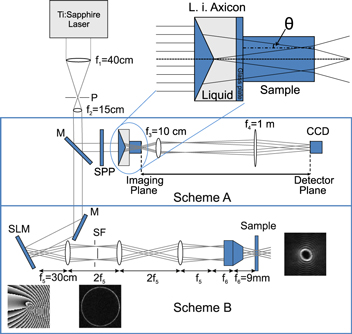
Figure 2. Setup to observe nonlinear propagation of Bessel beams and Bessel vortices. Scheme A uses a combination of spiral phase plate and liquid immersion axicon and permits moderate cone angles with helicity m = 1. Scheme B uses a spatial light modulator and a demagnifying telescope giving access to higher order Bessel beams at large cone angles. P—pinhole. SPP—spiral phase plate. M—mirror. CCD—charged coupled device. L.i. axicon—liquid immersion axicon. SLM—spatial light modulator.
Download figure:
Standard image High-resolution image3. Experimental results
3.1. Linear propagation
Figure 3 shows a comparison of propagation features for Bessel beams and Bessel-vortices in air, for the same cone angle θ = 2.2 deg. Very regular beam profiles were observed along the focal region, both for the Bessel beam and the Bessel vortex. From the spacing between the rings ( m), the Bessel cone angle can be calculated:
  , leading to
  , Focusing a Gaussian beam with an axicon is well known to result in a Bessel–Gauss beam that remains quasi propagation invariant along a focal region, the Bessel zone, of length
  . Adding helicity (here m = 1) to the Gaussian beam results in a higher-order Bessel–Gauss beam that remains quasi-propagation invariant over the same focal region. The highest intensity is reached on the surface of a hollow cylinder corresponding to the maximum of the
  function. More precisely, in the linear propagation regime, the intensity profile is determined by the relation [16]
where P denotes the input power of the Gaussian beam and z denotes the propagation distance from the tip of the axicon. With w0 = 4.4 mm, we obtain a Bessel zone LB = 11.3 cm. The highest intensity is reached at  and equals
  , where Mm = (1, 0.34, 0.24, 0.19, ...) denotes the maximum of the squared Bessel function of order m, for
  . We estimate that the beam enters a nonlinear propagation regime when the maximum intensity is sufficient to ionize the medium. With a threshold of 1012 W cm−2 in glass and 1013 W cm−2 in air, we need a minimum beam power of ∼240 MW in fused silica (corresponding to an energy of 13 μJ for a 45 fs pulse) and 3 GW in air (0.2 mJ). With pulse energies smaller than 100 μJ, we could explore the nonlinear propagation regimes in glass.

Figure 3. Images of the intensity profiles for the Bessel and the Bessel vortex beam taken at different distances behind the liquid-immersion axicon.
Download figure:
Standard image High-resolution image3.2. Nonlinear propagation
Propagation in the nonlinear regime was investigated by placing samples of fused silica with thicknesses 10, 20, and 40 mm close to the exit surface of the liquid immersion axicon. Figure 4 shows the fluence patterns at the exit of the 20 mm long fused silica sample when the input energy of the Gaussian beam is increased, for the Bessel beam (m = 0) and the Bessel vortex (m = 1). Again in both cases, clean Bessel-like beams are obtained, which look like the ideal Bessel beams  (with m = 0 or m = 1). We checked that these fluence patterns remain nearly identical for all sample lengths, i.e., nonlinear propagation is also featured by propagation invariance (data not shown). However, it is known that propagation invariant nonlinear Bessel beams exhibit ring compression (decrease of the ring spacing close to the main lobe with respect to the ring spacing of Bessel beams) and a loss of ring contrast, as the optical Kerr effect and multiphoton absorption (MPA) increase, respectively [17, 18]. Moreover, nonlinear propagation of Bessel beams with peak intensity above a certain threshold no longer leads to propagation invariant beams [19, 20]. As can be seen from the profiles in figure 4, ring compression and ring contrast loss is observed for the Bessel vortices as well, though higher pulse energy is required to observe the same ring spacing or contrast decrease as for Bessel beams with the same cone angle. Experimentally, white-light generation, another indicator for nonlinear propagation, was observed at 22.2 μJ for the Bessel beam and 36 μJ for the Bessel vortex, respectively.

Figure 4. Bessel and Bessel vortex beams in nonlinear propagation conditions imaged at the exit of a 20 mm long sample of fused silica. The cone angle is θ = 1.5 deg in fused silica. First row: nonlinear Bessel beams with input pulse energies of (from left to right) 6.9, 12.1, 17.4, 22.2 and 26.4 μJ. Second row: nonlinear Bessel vortices with input pulse energies of 14.8, 27.8, 39.9, 59.7, 66.6 μJ. Third row: line cuts (along x-direction) through the Bessel beam (left) and the Bessel vortex (right) at different energies.
Download figure:
Standard image High-resolution image3.3. Interpretation of observations
These observations are reminiscent of similar features previously reported for nonlinear Bessel beams: Porras and coworkers showed in 2004 the existence of Bessel-like propagation-invariant solutions to the nonlinear Schrödinger equation in the presence of Kerr effect and MPA [19]:
where in polar coordinates  . The parameters K0, n0, n2 and βK are provided in table 1. Recently, weakly localized propagation invariant solutions to equation (2) were found in the form of nonlinear high-order Bessel beams [14, 21]. These solutions have a stationary (z-independent) intensity profile and a linear dependence of the phase profile upon z:

where the wave vector shift is positive δ > 0, and the amplitude a(r) and phase gradient q(r) only depend on the transverse variable r. By introducing this amplitude and phase decomposition into equation (2), we find that a(r) and q(r) are solutions to Newton-like equations for a pseudo-particle with radial and angular positions a, ϕ, (with  ), angular momentum Jr ≡ k0 −1q(r)a2(r) and pseudo-time r:


where dots indicate differentiation with respect to r and the pseudo-potential is defined as  Vortex solutions must satisfy the boundary conditions a(0) = 0, q(0) = 0. The last boundary condition is governed by the decay rate as
  which corresponds to that of a Bessel beam carrying helicity m: as
  , nonlinearity is negligible and V(a) ∼ k0δa2, therefore, the solution tail can be viewed as a superposition of the two linearly independent Hankel functions that are solutions to the linearized equation (4):

 represent solutions carrying an outward or inward power flux, respectively. Their respective amplitudes αout,in differ,
  , leading to a fundamental feature of nonlinear Bessel vortices: a helical and inward power flux
![$[{{a}^{2}}q{{{\bf u}}_{r}}+(m{{a}^{2}}/r){{{\bf u}}_{\vartheta }}]$](https://content.cld.iop.org/journals/0953-4075/48/9/094006/revision1/jpb507369ieqn25.gif) transports energy from the tail of the beam to the most intense lobe where it is dissipated by MPA. In this respect, integration of equation (5) along the radial direction is equivalent to the energy conservation equation
transports energy from the tail of the beam to the most intense lobe where it is dissipated by MPA. In this respect, integration of equation (5) along the radial direction is equivalent to the energy conservation equation

which states that power losses due to MPA within a disk of radius r are compensated by the power flux flowing through its boundary (circle of radius r). This ensures propagation invariance of the nonlinear Bessel vortex [14, 21].
Examples of nonlinear Bessel beams m = 0 and vortices m = 1 integrated numerically are shown in figure 5 for a given cone angle and given arbitrary nonlinear parameter chosen to illustrate the main features of nonlinear Bessel vortices. For a given medium (n0, n2, βK), cone angle (δ or θ) and helicity m, a continuum of solutions of this type exists for a range of intensities ![$[0,{{I}_{{\rm max} }}]$](https://content.cld.iop.org/journals/0953-4075/48/9/094006/revision1/jpb507369ieqn26.gif) , where
, where  can be found only numerically and is usually two orders of magnitude larger than the breakdown threshold of the material. For example for Corning0211 glass,
  PW cm−2 [14]. As the helicity is increasing, the position of the most intense lobe is found at a larger radius. This radius is however slightly smaller than the radius of the linear solution with the same cone angle, i.e., the Kerr effect manifests itself in a compression of the most intense rings and a decrease of the ring spacing close to the center. Another manifestation of nonlinearity is the ring contrast which is decreasing as MPA increases. Asymptotically, this contrast can be readily obtained from an expansion of equation (6) as
  and reads:
  . Therefore the highest contrast C = 1 is reached for linear propagation, i.e., when
  , the inward and outward flux are balanced and there is no absorption (
 ). In contrast, the ring disappear, leading to zero contrast C = 0 if the power flux is directed only inward and the outward component is zero
  , corresponding to the highest possible MPA in a propagation invariant regime. The link between losses and the contrast
  , where
  , can be inferred from an introduction of the asymptotic expansion of equation (6) at large r into the energy conservation equation (7):
  . Since Bessel vortex beams are computed numerically, the link between losses and contrast can only be entirely specified numerically. The reader is referred to [21] for further details on this point.

Figure 5. Nonlinear Bessel beam (first column) and Bessel vortex carrying helicity m = 1 (second column). First row: amplitude in continuous curve. The red curve shows the linear solution with the same cone angle and normalized to the same maximum. Second row: phase gradient. Third row: the radial power flux rJr = k0−1 rqa2 represents power losses for a beam cross section of radius r, per length unit.
Download figure:
Standard image High-resolution imageWe interpret our observations as a manifestation of the reshaping of the beam into quasi-stationary nonlinear Bessel vortices. Propagation invariant nonlinear Bessel vortices are ideal beams carrying infinite power as shown by the  decay rate of their tail. Without this feature, MPA would unavoidably prevent stationarity. Rather than exact stationarity, quasi-stationarity arise over a finite length, the Bessel zone, because our Bessel vortices are shaped as the ideal propagation invariant solutions and apodized by a Gaussian beam, of width much larger than the most intense lobe of the Bessel-like solutions where MPA occurs. All features of nonlinear Bessel vortices are therefore observed within the Bessel zone. To complete characterization of the beam reshaping process during propagation, we investigated the decay of the contrast of the rings of the Bessel vortex beam during nonlinear propagation in fused silica samples of different thickness (10, 20, and 40 mm). We take line-cuts (in x-direction) through the beam center, being imaged at the exit of the samples. The line-cuts are normalized and Fourier transformed. We registered the relative amplitude of the Fourier peak associated with the transverse wave number of the Bessel vortex. Results are shown in figure 6 for a range of pulse energies up to 90 μJ. The relative amplitude of the Fourier peak decreases as nonlinear propagation becomes more prominent. In each case, we reported the onset of supercontinuum generation, which is a standard signature of nonlinear propagation. Supercontinuum generation was experimentally observed, when the Fourier contrast had decreased to about half the initial value. We mark the energies, when experimentally supercontinuum generation was observed by dashed lines in figure 6 for the different sample lengths.

Figure 6. Fourier contrast as function of pulse energy measured at the exit face of fused silica samples of lengths 10, 20 and 40 mm.
Download figure:
Standard image High-resolution imageBy using equation (1), we can give estimations of intensity levels at the exit face of the samples. For the three energies marked in figure 6, we obtain  W cm−2 for Ein = 66 μJ,
  W cm−2 for Ein = 50 μJ, and
  W cm−2 for Ein = 32 μJ. In other words, the point when the contrast is lost due to nonlinear propagation can be well identified with the same intensity levels on the back surfaces for the three different sample lengths. We can therefore conclude that the nonlinear propagation we observe, when the contrast is lost, happens at about the same intensity and in the vicinity of the respective back surface and not within the sample. As shown in the next section, this would be possibly different for longer samples which would include the peak of the pulse. The onset of nonlinear propagation arises for quite low intensity levels of 1012 W cm−2. At this intensity, no significant plasma density can be formed for a 45 fs pulse. For this cone angle (θ = 1.5 deg in fused silica), the Bessel vortex beam does not allow for the generation of hollow plasma cylinders.
3.4. Evaluation of the peak intensity and electron density on the hollow plasma cylinder
The maximum plasma density in the tubular plasma channel can be evaluated from the peak intensity, which in turn can be evaluated by energy conservation arguments similar to those applied for a Bessel beam [22]. The nonlinear Bessel vortex is assumed to have an invariant peak intensity Ip and shape over the Bessel zone. A fraction x of the input beam energy Ein is lost nearly exclusively in the main lobe to generate the plasma channel, by multiphoton ionization. This energy balance reads

where the intensity distribution is approximated by the product of a high-order Bessel beam profile by a Gaussian pulse:

By introducing this profile in equation (8), the peak intensity is explicitly determined by

where  .
.
Figure 7 shows the peak intensity and electron density evaluated as functions of the cone angle from equation (10) for different helicities of the Bessel vortex. Note that electron density is evaluated by considering only multiphoton ionization processes. When it approaches the density of neutral atoms, depletion of the valence band should lead to saturation. Depletion remains however negligible for electron densities smaller than 1021 cm−3. This simple scaling law predicts that a cone angle of 1.5 deg would lead to a peak intensity of 4 × 10¹² W cm−2 and an electron density of 1.3 × 1018 cm−3 for the Bessel vortex of lowest helicity m = 1. Peak intensity and electron density decrease with increasing helicity. An increase of the cone angle in the range 10–15 deg, is sufficient to reach peak electron densities in the range 4 × 10²⁰–1021 cm−3, for which energy transfer to the material can be deemed sufficiently efficient for inducing refractive index change or damage [23, 24].

Figure 7. Maximum Intensity and plasma density for a nonlinear Bessel vortex as a function of its cone angle for different helicities. Parameters correspond to fused silica and experimental scheme A with T = 45 fs, λ0 = 800 nm, n0 = 1.45, w0 = 4.4 mm, Ein = 30 μJ and x = 100%.
Download figure:
Standard image High-resolution image4. Numerical simulations
4.1. Model
The model used for numerical simulations consists in a (2+1)-dimensional unidirectional propagation equation for the nonlinear envelope E(x, y, z), which takes a canonical form [25]. As a nonparaxial equation, it is more easily written for the Fourier components of the electric field envelope ![$\mathcal{E}({{k}_{x}},{{k}_{y}},z)\equiv \mathcal{F}[E(x,y,z)]$](https://content.cld.iop.org/journals/0953-4075/48/9/094006/revision1/jpb507369ieqn42.gif) , where
, where  denotes Fourier transform in the transverse plane:
Nonparaxial diffraction is described in the propagation constant  . The Kerr effect is accounted for in the nonlinear polarization
 ![$\mathcal{P}({{k}_{x}},{{k}_{y}},z)\equiv \mathcal{F}[P(x,y,z)]$](https://content.cld.iop.org/journals/0953-4075/48/9/094006/revision1/jpb507369ieqn45.gif) , with
, with  , where
 . The current
![$\mathcal{F}[J(x,y,z)],$](https://content.cld.iop.org/journals/0953-4075/48/9/094006/revision1/jpb507369ieqn50.gif) where
where  comprises two contributions due to MPA and plasma-induced effects (PL). The contribution of MPA reads
  , with coefficient βK and number of photons K.
Plasma-induced effects, i.e., plasma absorption and plasma defocusing are included in a single expression for the current, derived from the Drude model:

where τc denotes a phenomenological collision time in the medium and ρc, the critical plasma density beyond which the medium is no longer transparent.
The evolution of the electron plasma density is modeled by a rate equation modeling multiphoton and avalanche ionization with cross section σ, as well as electron plasma relaxation with typical time τr:

We consider large cone angles, giving rise to a short Bessel zone over which dispersion is negligible. The plasma density is therefore evaluated in the frozen time approximation that consists in using a Gaussian pulse with the nominal duration of the laser.
In table 1, we provide the model parameters used for fused silica and BK7 at the pulse central wavelength of 800 nm, together with references from which the values were obtained.
Table 1.
Parameters uses for modeling the response of fused silica and BK7. Refraction index: n0. Kerr index coefficient: n2 [23, 26]. Number of photons:  . Coefficient for multiphoton absorption:
  [27]. Bandgap: Ui collision time:
  . Plasma relaxation time:
  . Neutral density:
  . Critical plasma density:
  .
.
| Fused silica | BK7 | |
|---|---|---|
| n0 | 1.45 | 1.51 |
| n2 (cm2 W−1) | 3.54 × 10⁻¹⁶ | 3.45 × 10⁻¹⁶ |
| K | 5 | 3 |
 (cm2K−3 W−(K − 1)) (cm2K−3 W−(K − 1)) |
6.8 × 10−50 | 3.9 × 10⁻²⁸ |
| Ui (eV) | 7.1 | 4.2 |
 (fs) (fs) |
1.3 | 1 |
 (fs) (fs) |
150 | 2000 |
 (cm−3) (cm−3) |
2.1 × 10²² | 2.1 × 10²² |
 (cm−3) (cm−3) |
1.8 × 10²¹ | 1.8 × 10²¹ |
4.2. Results
4.2.1. Nonlinear Bessel vortex in fused silica at small cone angles
Figure 8 shows simulation results for the experimental scheme A with a cone angle of θ = 1.5 deg in fused silica. First, we note that the sample thickness was approximately half the length of the Bessel zone. For a pulse energy of 7 μJ, the beam forms a Bessel vortex with its typical main ring surrounded by lower intensity rings. The highest intensity reaches 400 GW cm−2 and does not lead to a significant plasma density. The highest calculated plasma density is about 1010 cm−3 (not shown). This regime therefore shows the formation of a quasi linear Bessel vortex. If the input energy is increased, there is however no abrupt threshold but a continuous transition between this regime and the nonlinear regime featured by the formation of propagation invariant nonlinear Bessel vortices, as found semi-analytically in section 3.3. By further increasing the input energy above a certain threshold, the propagation invariant regime is no longer found. Figure 8 shows that at 66 μJ, the uniform ring formed in the beginning of the Bessel zone undergoes instability, forming a high intensity peak that rotates around the propagation axis at a fairly regular rate, reflecting the angular momentum carried by the beam. The highest intensity of 5 TW cm−2 is sufficient to generate a plasma of density of 1019 cm−3. However, this density might be still too low to induce damage in the material. These experimental conditions might be just below threshold for refractive index change in fused silica. As a final comparison with the experimental patterns, we note that the rotating peak appears above 32 μJ, similarly to the results in [14]. At higher energy the contrast gets smoothed out, and the rotating peak is not so pronounced as in the simulation. Dispersion of the 45 fs pulse was neglected in the simulation but could stretch the pulse by a factor of ∼2.3 over 6 cm in the experiment and therefore decrease the peak intensity and shift the instability threshold towards larger pulse energies.

Figure 8. (a) and (b) Numerically simulated intensity profile along the propagation axis for the experiment (scheme A) with small cone angle. The pulse duration is 45 fs and pulse energies are (a) 7 μJ and (b) 66 μJ. (c) Plasma density obtained for intensity shown in (b). The colorbar indicates  when the plasma density ρ is expressed in cm−3.
Download figure:
Standard image High-resolution image4.2.2. Nonlinear Bessel vortex in BK7 at large cone angles
Figure 9 shows simulation results for experimental parameters in scheme B, performed at higher cone angle of 11 deg in BK7 (16.95 deg in air). The experimental scheme shown in figure 2 is described in more detail in section 5. The simulations allow us to anticipate a high electron density (1021 cm−3) distributed uniformly on a hollow cylinder extending over the entire thickness of the BK7 sample (100 μm). Uniformity appears after a regularization stage in the first microns after the entrance face of the sample where the intensity is sufficiently high for secondary lobes of the Bessel vortex to also generate plasma. However, it is clear that a propagation invariant regime takes place. The peak intensity is a factor of 2 smaller than in the simulation for the small-cone-angle, 45 fs pulse. Among the reasons leading to a higher electron density, not only has BK7 a slightly smaller bandgap than fused silica but also the picosecond pulse used for BK7 facilitates the generation of electrons by avalanche while requiring a lower intensity to reach the same level as that obtained with a fs pulse. Finally, propagation invariant nonlinear Bessel vortices at a given peak intensity are more stable for large cone angles and can therefore attract the beam dynamics [14].
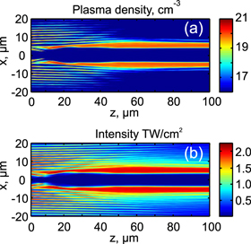
Figure 9. Numerically simulated plasma density and intensity profile along the propagation axis for the experiment (scheme B) with large cone angle. The pulse duration is 1 ps and pulse energy is 37 μJ.
Download figure:
Standard image High-resolution image5. Material structuring with single shot picosecond laser Bessel vortex beams
In order to assess the potential of intense Bessel vortex beams for microstructuring the bulk of glass materials, we performed microfabrication tests in single shot with picosecond laser pulses for different cone angles. In this case (scheme B in figure 2) the laser source was a 20 Hz regeneratively amplified Ti:Sapphire laser system delivering λ = 800 nm, 40 fs pulses with about 30 nm bandwidth, that could be chirped up to picosecond duration. The Gaussian laser output beam was spatially filtered, demagnified and sent to a spatial light modulator (SLM, (PLUTO, Holoeye) for the beam shaping. A 10 nm bandwidth interference filter was used to reduce the laser bandwidth in order to improve the efficiency and quality of the phase modulated beam reflected by the SLM. The pulse energy was adjusted by means of a half-waveplate combined with a linear polarizer, and a mechanical shutter on the beam line allowed the selection of single pulses for single shot machining. High-order Bessel-Beams (Jm) are generated by applying onto the SLM a spatial phase modulation corresponding to that of an axicon superimposed with a phase mask imposing a helicity of order m (or topological charge), which determines the radius of the innermost ring. By changing the axicon angle parameter (linked to the Bessel cone angle) we can adjust the Bessel zone length and the Bessel core size or ring thickness. The spatial quality of the generated beam is guaranteed by a far-field spatial filtering after the SLM. After demagnification by means of a telescope constituted by a f5 = 300 mm focal length plano-convex lens and a 0.45 N.A. 20 X microscope objective, the resulting high-order Bessel beam Jm is then incident onto 100 μm thin glass samples. The sample is placed on a computer controlled three-axes motorized stage for precise position adjustment during the microfabrication process. Before machining, the evolution of the intensity beam profile after the demagnification set-up is monitored by means of an imaging system in combination with a CCD camera. Figure 10 shows the imaging of the Bessel vortices taken exactly at the sample position but in air. For machining, we added the glass sample. The Bessel zone was 200 μm, the ring thickness and diameter were about 1 and 8 μm, respectively.

Figure 10. Images of the Bessel vortices at different propagation distances in air. Cone angle in air θ = 16.95 deg.
Download figure:
Standard image High-resolution imageOur tests showed that no clean tubular structure writing in glass was obtained below a certain cone angle (7 deg in glass for our experimental conditions). We attribute this to the fact that propagation invariant Bessel vortex beams with an intensity sufficient to ionize glass significantly only exist for cone angles exceeding a certain threshold [14]. For small cone angles, propagation invariant Bessel vortex beams can undergo instability since nonlinear effects are predominant (nonlinear length is much shorter than the length over which the Bessel core regenerates due to the refilling from an external ring). In order to cure this issue whithout increasing cone angles to extremely large values, we increased the pulse duration above 1 ps with the goal of simultaneously (i) reducing the peak intensity of the propagation invariant Bessel vortex beam, thus increasing the nonlinear length and the stability of the Bessel vortex beam, and (ii) increasing the nonlinear absorption associated with the generation of electrons by avalanche ionization. We also note that similarly to the propagation of intense Bessel beams, picosecond pulses are associated with weaker electron carrier defocusing, which may facilitate reaching a propagation invariant regime and a more efficient laser energy deposition [28].
Figures 11 and 12 show pictures of clean high aspect ratio tubular microstructures obtained in single shot for a J8 Bessel beam with cone angle θ = 11 deg in BK7 glass, obtained with 1 ps, 800 nm pulses. Figure 11 shows the input and exit surfaces of the glass sample (respectively denoted as top and bottom in the figure) for different pulse energies. Clean ring structures matching the radius of the J8 beam are observed, indicating the presence of a tubular refractive index change over the entire thickness of the sample. This structure is clearly shown in figure 12 for a pulse energy of 35 μJ. Similar results were obtained with fused silica (not shown) with lower pulse energy. In our geometry, when using pulse duration much shorter than 500 fs, the tubular structure was weaker and traces on the surfaces were not so evident as those shown in figure 11.

Figure 11. Optical microscope images of top and bottom glass sample surfaces micromachined with J8 Bessel vortex beam in single shot, and for three different energy values E = 22 μJ (a), E = 37 μJ (b) and E = 56 μJ (c). The cone angle is θ = 11 deg in BK7.
Download figure:
Standard image High-resolution image
Figure 12. Side view of a 100 μm thick glass sample machined in single shot with the J8 Bessel vortex beam featured by an energy per pulse E = 37 μJ. Cone angle: θ = 11 deg in BK7. Note that only the two line traces that cross the whole thickness are results of the micromachining process; the others, in the lower part of the sample image result from irregularities of the sample side surface.
Download figure:
Standard image High-resolution image
6. Conclusions
Clean Bessel–Gauss beams and Bessel–Gauss vortices were generated by various methods: a combination of a liquid-immersion axicon and a SPP allowed flexibility in the regime of small cone angles. Through samples of 10, 20, and 40 mm of fused silica, Bessel–Gauss vortices were shown to propagate as quasi invariant beams with pulse energy of up to 30 μJ before nonlinear propagation degraded the contrast of the hollow beam. This is much more than the critical energy (associated with the critical power of ∼200 MW) in fused silica, which is below 1 μJ. However, the intensity at which the ring structure starts to undergo symmetry breaking in our experiments at small cone-angles does not seem to be sufficient to generate a dense plasma. The same propagation regime in air would lead to an underdense hollow plasma channel with ideal density and dimensions for the generation of a transient waveguide for microwaves [29, 30]. In the femtosecond regime, we have proposed a simple scaling law to link the laser and material parameters to the density of electrons generated by multiphoton ionization.
The regime of larger cone angles was tackled using a SLM and a demagnification system (telescope and microscope objective). Quasi propagation invariant annular Bessel beams were shown to lead to tubular light filaments, which in turn generate a hollow plasma channel in a BK7 glass with density evaluated by numerical simulations about 1021 cm−3. Although the physical mechanism at the origin of material densification was not investigated here, observation of the sample after single shot illumination by a picosecond pulse shows that pulses of a few microjoules with picosecond durations and Bessel cone angles larger than 7 deg lead to a tubular refractive index change over the entire Bessel zone (sample thickness of 100 μm).
Acknowledgments
We acknowledge funding from Deutsche Akademie der Naturforscher Leopoldina (grant no. BMBF-LPD 9901/8-181), the French National Research Agency, ANR contract 2011-BS04-010-01 NANOFLAM, Region Franche-Comte and the International Program for Scientific Cooperation (PICS) at CNRS.