
Abstract
We report on the development of foam-based double-layer targets (DLTs) for laser-driven ion acceleration. Foam layers with a density of a few mg cm−3 and controlled thickness in the 8–36 μm range were grown on μm-thick Al foils by pulsed laser deposition (PLD). The DLTs were experimentally investigated by varying the pulse intensity, laser polarisation and target properties. Comparing DLTs with simple Al foils, we observed a systematic enhancement of the maximum and average energies and number of accelerated ions. Maximum energies up to 30 MeV for protons and 130 MeV for C6+ ions were detected. Dedicated three-dimensional particle-in-cell (3D-PIC) simulations were performed considering both uniform and cluster-assembled foams to interpret the effect of the foam nanostructure on the acceleration process.
Export citation and abstract BibTeX RIS

Original content from this work may be used under the terms of the Creative Commons Attribution 3.0 licence. Any further distribution of this work must maintain attribution to the author(s) and the title of the work, journal citation and DOI.
Introduction
Laser-driven ion acceleration represents an appealing solution for a large number of scientific and technological applications requiring compact and efficient high-energy proton/ion beam sources [1, 2]. In this scheme, ions are accelerated by irradiating μm-thick solid foils with ultra-intense, ultra-short laser pulses. The electrons of the target absorb a sizable fraction of the incident laser energy. Light ion species adsorbed on the non-illuminated foil surface are accelerated by the intense electric fields generated by the expansion of the electron sheath. This mechanism is known as target normal sheath acceleration. Laser-driven ion sources provide ultra-short, low emittance ion bunches containing several ion species (especially protons and carbon ions), with a broad energy spectrum and maximum energy up to ∼60 MeV for protons and ∼25 MeV/nucleon for carbon ions. They require a relatively simple experimental apparatus and may allow the reduction of radioprotection issues related to ion beam transport. Thanks to their properties, laser-based ion sources may find applications in several fields: material characterisation [3] and manufacturing [4], testing and calibration of radiation detectors and beam dumps [5], stress testing of components for spacecrafts [6], nuclear fission and nuclear reactors [7] and the production of radioisotopes for medical imaging, such as  Tc, 82Sr and 68Ge [8]. Depending on the specific application, ion sources should provide energies in the 1–100 MeV/nucleon range and average currents from a few nA up to a few mA. These performances have not been achieved so far by laser-driven ion acceleration.
In order to meet these requirements, a laser-driven ion source needs to exploit high-repetition-rate laser systems delivering relatively low energy pulses. Therefore, the development of smart target concepts compatible with high repetition rates and able to enhance acceleration performances would represent fundamental progress. To this end, several target configurations have been investigated in the last few years: ultra-thin foils [9–11], reduced mass targets [12], micro-spheres targets [13–15], grating targets [16] and ultra-thin diamond-like carbon foils covered with carbon nanotubes [17].
Target configurations resulting in the formation of a controlled near-critical (nc) plasma layer on the illuminated surface of a μm-thick solid foil have shown promising results in numerical studies [18, 19]. According to particle-in-cell (PIC) simulations, the nc plasma layer should enhance the laser-target coupling and, as a consequence, the energy conversion from laser to ions. Since the laser pulse can penetrate the low-density layer, laser absorption mechanisms can occur within the entire plasma volume. In principle, several mechanisms can contribute to the laser absorption enhancement in the near-critical density regime, such as pulse channeling and direct electron acceleration at the channel walls [19] or further pulse focusing and shaping [17, 20]. In turn this would lead to an increase in both the energy and number of accelerated ions for optimal plasma layers with respect to μm-thick solid foil targets (ST). The optimal density of the low-density layer is found to be in the range of  and the optimal initial thickness is predicted to range between 10 and 20 μm [18, 19]. Considering the fully ionized carbon plasma and laser wavelength of 0.8 μm, an initial density of 5.7 mg cm−3 is required. This value is 400 times lower than graphite density. Density values of a few mg cm−2 can only be reached in porous nanostructured materials, i.e. foams. The fabrication and characterisation of foam layers with such properties requires the development of advanced material science techniques. Therefore, a reliable and simple technique would be needed for the production of foam layers with tunable properties and good adhesion to a solid substrate on large areas. The capability to produce such materials can be of interest also to explore other laser-driven ion acceleration mechanisms [1, 2].
Previous experimental results showed a promising enhancement of acceleration performances using carbon foam double-layer targets (DLTs) in terms of both proton energy and number at moderate laser intensities (∼1018 W cm−2) [21]. An extension of this study to laser intensities in the fully relativistic regime (above 1020 W cm−2) is certainly of major interest to investigate the behaviour of DLTs. Moreover, deeper insight is necessary to provide a satisfactory description of the complex laser–plasma interaction in the near-critical density regime, especially in the case of nanostructured foam materials. To this end, the development of innovative computational tools would be required, for example to take into account the peculiar morphology of the foam layer.
In this work we report on the development of a technique for the production of foam-based targets and on an extensive experimental and numerical investigation aimed at characterising and optimising this target design in the high intensity regime (>1020 W cm−2). The pulsed laser deposition (PLD) technique [22] was adopted to grow carbon foam layers with a density below 10 mg cm−3, a controlled thickness in the 5–70 μm range and satisfactory spatial uniformity. An experimental campaign was performed using the 1 PW laser system [23] installed at the Center for Relativistic Laser Science (CoReLS), Institute for Basic Science (IBS) in Korea, to investigate the dependence of the acceleration performances on the properties of foam and Al foil and on laser parameters. The maximum and average ion energy and accelerated particle numbers were studied as a function of: the near-critical foam thickness (in the 8–36 μm range); the foam density (7 and 25 mg cm−3); the Al foil thickness (0.75 and 1.5 μm); the laser polarisation (s, p and circular) and the laser intensity (0.5– W cm−2). The interpretation of the experimental results is supported by three-dimensional PIC (3D-PIC) simulations. Simulations were performed considering both uniform and cluster-assembled foams to get a better insight of the interaction between the ultra-intense laser pulse and nanostructured foam in the near-critical density regime and to interpret the effect of the foam nanostructure on the acceleration process.
Results and discussion
Growth of nanostructured carbon foams
Porous carbon foams were grown at the Micro and Nanostructured Material Laboratory of Politecnico di Milano by adopting the PLD configuration proposed in [22]. The PLD approach for carbon foam production is based on the ablation of a pyrolytic graphite target by the second harmonic (532 nm) of a Nd:YAG laser (pulse duration 5–7 ns, repetition rate 10 Hz, fluence 0.8 J cm−2) in a chamber filled with Ar. The ablated species propagate in the deposition chamber and are collected on a solid substrate forming a thin film. The presence of a buffer gas with pressure in the 102 Pa regime enhances the collision frequency between ablated species, leading to the formation of clusters and nanoparticles in the plasma plume and to the growth of cluster-assembled films with porous morphology.
In general, PLD-grown carbon foams were characterised by an intrinsic inhomogeneity in the distribution of the deposited material caused by the low energy of the impinging species. Therefore, the deposition process was revised to obtain suitable foam uniformity, since the use of a gas flux in the deposition chamber adopted in [22] resulted in insufficient process reproducibility due to fluid-dynamic effects in the deposition chamber. In this work, a different configuration was exploited: carbon foams were grown with a lower graphite-to-substrate distance ( cm) and higher gas pressure (
 Pa). A significant enhancement of the process reproducibility was observed since the particle propagation towards the substrate was less affected by fluid-dynamic effects in the deposition chamber. Figure 1 compares the morphologies obtained with the two configurations. The new configuration allowed for the production of films with a significantly lower characteristic foam inhomogeneity scale (0.5 μm) with respect to the previous configuration (5–7 μm), thanks to the reduced propagation of the ablated material in the transverse direction. In addition, higher deposition rates were observed for this configuration, allowing us to adopt shorter deposition times.

Figure 1. Foam uniformity control. Scanning electron micrographs of carbon foams deposited in Ar (a)  Pa,
Pa,  cm, for 3 min; (b)
  Pa,
Pa,  cm, for 10 min. The scale bar is common for both frames.
Download figure:
Standard image High-resolution imagePLD deposits typically exhibit a Gaussian-like thickness profile. As a consequence, static depositions only allow the production of small samples with a uniform area of about 1 cm2. Since large areas can be required in actual target arrangements, this issue was addressed by suitably translating and rotating the solid substrate in order to overlap the Gaussian material distributions produced by subsequent laser pulses. This method resulted in the production of foams with an almost uniform thickness profile on surfaces with diameters up to 50 mm (thickness standard deviation <15%).
The good degree of control on the film density and morphology required for target manufacturing was achieved by tuning the buffer gas pressure. The mass density of the foam layers was assessed with an innovative technique combining cross-sectional scanning electron microscope images and energy dispersive x-ray spectroscopy [24]. A decreasing trend of the foam density versus Ar pressure was observed, saturating around 7 mg cm−3 in the 300–700 Pa pressure range. It is interesting to note that the density variations were related to modifications occurring at the sub-micrometer scale rather than in the dimensions of the macro-aggregates. The foam thickness (determined using scanning electron microscopy) was controlled by tuning the duration of the deposition process. For the thickness range of interest in this experiment (up to 36 μm), the foam thickness increased linearly with a deposition rate of almost 2 μm min−1 (for diameters of about 50 mm). In other regimes (not shown), thickness saturation effects were observed as a consequence of foam structural compression or mass losses due to vibrations of the porous structure.
To summarise, PLD proved to be a reliable and flexible tool for the production of foams with tunable properties with densities down to 7 mg cm−3 and thicknesses from 5 to 70 μm on substrates 50 mm wide. Thicker foams can be grown by suitably increasing the deposition process duration. The coated area can be further extended while keeping the process duration in the tens of minutes range. Other techniques considered so far for the production of foams for laser–matter interaction experiments are, for example, floating catalyst chemical vapour deposition [25] and high internal phase emulsion (HIPE) templating [26, 27]. Even though these techniques may possibly guarantee even better microscale uniformity with respect to PLD, in the first case the target manufacturing process is much more complex, while HIPE does not allow the growth of thin layers adhering to a solid substrate.
For the laser–driven ion acceleration experiments described in this work, foam-based DLTs were produced by growing a foam layer directly on an Al foil ( ), in turn glued on a hollow metallic support. As shown in figure 2, a protective frame with conic holes was adopted to prevent extensive foam damage and to preserve neighbouring targets. The same target holder assembly was adopted for STs. Figure 3 illustrates the morphology of foams considered in this experiment. A list of DLTs for the experimental campaign is reported in table 1. Foam layers with thickness of about 8, 12, 18 and 36 μm and an average mass density of
  were grown on 0.75 μm thick Al foils with
  cm and
  Pa (figure 3(a)). 12 and 18 μm thick near-critical foams were grown in the same conditions on 1.5 μm-thick Al foils. Foams with a density of
  and a thickness of about 12 μm were grown with
  cm and
  Pa on 0.75 μm thick Al foils (figure 3(b)). Assuming a full ionization of the carbon foam layer and laser wavelength
  m,
m,  and
and  correspond to 1.2 nc and 4.3 nc.

Figure 2. DLT assembly. Carbon foam was deposited onto a thin Al foil attached on a hollow metallic support. The target holder assembly was completed with a second metallic support to protect the foam layer. On the left, the shape of the holder for a single target is shown with larger magnification. On the front side a conical hole is present (1 mm diameter at the target surface, aperture angle ∼90°); on the rear side the hole is cylindrical (4 mm diameter).
Download figure:
Standard image High-resolution image
Figure 3. Target morphology. Scanning electron micrographs of carbon foams with densities of about (a) 7 and (b) 25 mg cm−3. The scale bar is common for both frames.
Download figure:
Standard image High-resolution imageTable 1. List of DLTs adopted in the experimental campaign.
| n/nc | Foam density  |
Foam thickness μm | Al foil thickness μm |  Pa Pa |
 cm cm |
|---|---|---|---|---|---|
| 1.2 |  |
8, 12, 18, 36 | 0.75 | 500 | 4.5 |
| 1.2 |  |
12, 18 | 1.5 | 500 | 4.5 |
| 4.3 |  |
12 | 0.75 | 30 | 8.5 |
Enhanced laser-ion acceleration in DLTs
The setup adopted for the experimental campaign is schematically illustrated in figure 4. The experiment was performed using the 1 PW Ti:sapphire laser installed at CoReLS, IBS. The laser system delivers 30 fs laser pulses with an 800 nm centre wavelength. The typical laser spectrum and shape are found in [23]. A double plasma mirror system was used to obtain temporal contrast better than 10−11 up to 10s ps before the main pulse. The detailed configuration of the double plasma mirror system is described in [11] (and the related supplemental material). The double plasma mirror system provided laser pulses with s-polarisation. Therefore, an additional wave plate was installed just in front of the off-axis parabolic mirror to change the polarisation on the target. Laser pulses with p- and circular (c-) polarisations were obtained by inserting half and quarter-wave plates, with 82% and 87% transmission coefficients, in front of the off-axis parabolic mirror. The laser pulse was focused with an f/3 off-axis parabolic mirror (focal length of 600 mm) with an incidence angle of 30° with respect to the target normal. The focal spot shape was characterised with a high-magnification focal spot monitoring system [28]. A typical spatial distribution of the focal spot is shown in the inset of figure 4. The focal spot had FWHM lower than 5 μm and about 22% of the total energy was concentrated in that area. The pulse energy on the target was varied between 1 and 7.4 J by changing the pumping energy in the PW amplifier, resulting in intensities on the target ranging from  to
to  for s-polarisation. Due to the transmittance of the wave plates, the maximum intensity was slightly lower for p- and c-polarisation for the same PW amplifier pumping energy. Ion spectra were measured using a Thomson parabola spectrometer positioned along the direction normal to the rear target surface. The response of the spectrometer was absolutely calibrated by using a slotted nuclear track detector, CR-39, installed in front of the micro channel plate. The ion number was evaluated in a limited solid angle
  sr. As a consequence, slight variations in the orientation of the target rear surface could result in fluctuations of both the ion number and the maximum energy. The maximum proton and carbon energies were statistically analysed using the data obtained with identical laser and target conditions. Several laser shots (between 3 and 15) were considered to calculate the average and standard deviation of the maximum ion energies. The data points and error bars in figures 5(a)–7 correspond to the average and standard deviation values.
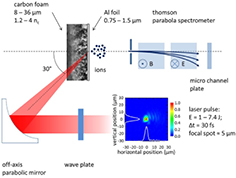
Figure 4. Experimental setup. The laser pulse is focused on the target by an off-axis parabolic mirror with a 30° incidence angle. Accelerated ions are detected by a Thomson parabola spectrometer positioned along the direction orthogonal to the target rear surface.
Download figure:
Standard image High-resolution image
Figure 5. Role of the foam thickness. The results refer to a 0.75 μm thick ST and a DLT composed of 0.75 μm thick Al foils covered with 8–36 μm thick foams irradiated for the maximum laser intensities. (a)  and
and  are shown as a function of the foam thickness for s- (blue squares), p- (red triangles) and c- (black circles) polarisation. (b) Role of the foam thickness. The results refer to a 0.75 μm thick ST and DLTs composed by 0.75 μm thick Al foils covered with 8–36 μm thick foams irradiated with the maximum laser intensities. (a)
  and
and  are shown as a function of the foam thickness for s- (blue squares), p- (red triangles) and c- (black circles) polarization. (b) Representative proton spectra observed for DLTs with 8 μm (I), 12 μm (II) and 18 μm (III) thick foams and a 0.75 μm thick ST (IV) in the case of s-polarization.
Download figure:
Standard image High-resolution image
Figure 6. Role of foam thickness and laser intensity. The results refer to the 0.75 μm thick SFT and the DLTs composed of 0.75 μm thick Al foils covered with 8–36 μm thick foams irradiated with s-polarisation.  is reported as a function of the laser intensity for the ST (black circles) and DLTs with 8 μm (red squares), 12 μm (green triangles) and 36 μm (blue diamonds) thick foams.
Download figure:
Standard image High-resolution image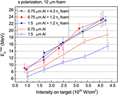
Figure 7. Role of Al foil thickness, foam density and laser intensity. Results refer to 0.75 μm and 1.5 μm thick STs (red open squares and blue open triangles, respectively); DLTs composed of 12 μm thick near-critical foams and Al foils with a thickness of 0.75 μm (red squares) and 1.5 μm (blue triangles); DLT composed of 12 μm thick foam with density  and Al foil with the thickness 0.75 μm (half-filled squares).
  is reported as a function of the laser intensity for s-polarisation.
Download figure:
Standard image High-resolution imageThe effect of the foam thickness on the acceleration performances was investigated for s-, p- and c-polarisation in the 8–36 μm range, using near-critical foams deposited on 0.75 μm thick Al foils (see figure 5). The maximum energies observed with STs for p-, s- and c-polarisation were 22, 18 and 10 MeV for protons and 80, 90 and 40 MeV for C6+. This strong dependency on the polarisation is due to a different laser absorption efficiency, well-known in the literature [1, 2]. On the contrary, for DLTs the maximum ion energy was not affected by the polarisation. In figure 5(a), the maximum energies of protons and C6+ ions ( and
and  ) are reported as a function of the foam thickness for the maximum available laser intensity.
  and
and  decrease for an increasing foam thickness. This monotonic trend suggests that the thickness optimum should be ⩽8 μm. For the thinnest foams, 8 μm and 12 μm, a systematic enhancement in the maximum energy of both protons and C6+ ions with respect to STs was observed for the three polarisations.
  MeV and
  MeV were detected for the 8 μm thick foam.
Figure 5(b) illustrates examples of proton spectra observed for different foam thickness values with s-polarisation at the maximum available laser intensity. An enhancement of the number of high energy protons ( MeV) per solid angle unit (
 sr−1) was observed for 8 μm and 12 μm thick foams. For 8 μm thick foams,
  was about
  sr−1.
sr−1.  decreased to
  sr−1 for 12 μm thick foams. The number of accelerated particles for 18 μm thick foams (
 sr−1) was found to be about four times higher with respect to the ST (
 sr−1), even though in this case the proton maximum energies obtained with DLT and ST were comparable. In table 2, the gain factors
  for 8 μm thick foams are reported for s-, p- and c-polarisation. An enhancement in the number of accelerated particles was observed for the DLT, whenever a comparison with the ST was possible. In the case of p-polarisation,
  around 6.8 was observed for energy between 18 MeV and
  (maximum proton energy for a DLT). For 8 μm thick foams, the proton temperature (estimated by an exponential fit of the high energy part of the spectra) was 5.1, 4.9 and 7 MeV for s-, p- and c-polarisation, respectively, to be compared with 2, 2.7 and 0.8 MeV observed for the ST.
Table 2. Gain factors  in several energy intervals for targets composed of an 8 μm thick near-critical foam and a 0.75 μm thick Al foil, irradiated with the maximum laser intensity.
| Energy interval (MeV) |  s-pol s-pol |
 p-pol p-pol |
 c-pol c-pol |
|---|---|---|---|
| 8–10 | 7.1 | 1.6 | 7.9 |
8– |
8.7 | 1.7 | 20.5 |
| 14–16 | 12.9 | 1.8 | — |
14– |
22.4 | 2.7 | — |
| 18–20 | — | 2.8 | — |
18– |
— | 6.8 | — |
Notes:  and
and  were calculated by integrating the experimental spectra in the corresponding energy intervals. Blank cells are reported for energy intervals in which no protons were detected for the ST.
The enhancement of the performances obtained for 8 and 12 μm thick foam targets with respect to solid foils was systematically observed in the whole intensity range, as shown for instance for s-polarisation in figure 6. The maximum proton energy increased almost linearly with the laser intensity. A similar trend was observed for p- and c-polarisation.
A second set of targets was considered to investigate the role of Al foil thickness and foam density. As an example, figure 7 illustrates  for 12 μm thick foams and s-polarisation. The effect of the Al foil thickness was studied using 0.75 and 1.5 μm thick Al foils for both STs and DLTs with near-critical foam. For STs a strong dependence of the acceleration performances on the Al thickness was observed, as expected from the literature [16, 29, 30]. In contrast, no systematic difference in
  was observed for DLTs between the case of 0.75 and 1.5 μm Al foils. The reduced sensitivity of the acceleration process to the Al thickness is in good agreement with previous numerical results [19]. 12 μm thick foam layers with near-critical (
 ) and with slightly over-critical (
 ) density on 0.75 μm thick Al foils were adopted to investigate the effect of the foam density on the acceleration performances. The data showed no systematic difference between the near-critical and slightly over-critical foam layers.
Numerical investigation
Large scale 3D simulations were performed with the open source PIC code PICCANTE [31]. The numerical simulations aimed to support the interpretation of the experimental results and to investigate the effect of the foam nanostructure on the laser–target interaction process and on the acceleration performances. Three different targets were tested in the simulations:
- a simple Al foil
- an Al foil coupled to a uniform near-critical foam
- an Al foil coupled to a nanostructured near-critical foam (see below)
In the literature, near-critical plasmas are typically simulated as a uniform density layer [18]. This approach is certainly valid for the interaction of a  laser pulse with gas jets [32] or for solid-density targets having structures with a spatial inhomogeneity smaller than the laser wavelength (e.g. nanotube array targets [17]). However, PLD foam targets are composed of nanoclusters aggregated in larger structures, with a typical spatial inhomogeneity comparable with the wavelength. Since in the experiment an ultra-high contrast laser pulse was used, these large structures might survive long enough to influence the dynamics of laser-foam interaction. In order to address these possible issues, we also simulated 'realistic' foam targets consisting of a collection of dense nano-spheres (
 , 50 nm radius) arranged according to a diffusion limited aggregation (DLA) model [33, 34]. The resulting porous structure was characterised by an occupation factor of about 2%, giving an average electron density approximately equal to nc. The cluster-assembled foam was grown up to a maximum height of 12.5 μm and was subsequently cut at 8 μm, in order to avoid huge inhomogeneities.
The simulations were performed on the high-performance computing machines of CINECA, Italy—the Intel Tier-1 Galileo—and the IBM BlueGene/Q Tier-0 FERMI. The parameters of the simulations are summarised in table 3. The laser field amplitude had a  -function longitudinal profile with intensity FWHM set to 31 fs. The transverse radial profiles of the laser fields are Gaussian with a waist of w0 = 4 μm. The maximum laser intensity at focus is
  corresponding to a normalised amplitude a0 = 18 for linear polarisation (
 where I0 is the peak intensity). The laser pulse was focused at the solid foil front surface with an angle of incidence of 30°. The Al foil was represented as a uniform plasma of electrons and Al13+ ions with an electron density of
  and a thickness of
  m and it was sampled with 40 particles per cell. Attached to the rear side of the main target a thin (0.02 μm) low-density (
 ) CH-plasma simulated the presence of a layer of contaminants on the surface of the foil. For the case of a uniform foam, C6+ plasma with a density of
  was considered and sampled with four particles per cell. For nanostructured foam, a much higher number of particles per cell was necessary to obtain a good sampling of the dense clusters. The clusters were spheres with a radius of 50 nm; the average density of the layer was 1nc and the plasma was sampled with 125 particles per cell.
Table 3. Parameter list for 3D simulations.
| Params | Foil | Uniform | DLA |
|---|---|---|---|
| Resolution (ppλ) | [40, 20, 20] | [40, 20, 20] | [50, 20, 20] |
Al  |
40 | ||
| Al thickness (μm) | 0.8 | ||
| Al ppc (e−) | 40 | ||
Foam  |
— | 1 | 1 (Average) |
| Foam thickness (μm) | — | 8 | 8 |
| Foam ppc (e−) | — | 4 | 125 |
CH  |
10 | ||
| CH thickness (μm) | 0.02 | ||
CH ppc ( ) ) |
8 | 8 | 100 |
| Laser incidence | 30° | ||
| Laser λ (μm) | 0.8 | ||
| Laser polarisation | circular, linear (p) | ||
| Laser a0 | 18 | ||
| Laser FWHM (fs) | 31 | ||
| Laser waist (μm) | 4 | ||
Notes: ppc stands for particles per cell, ppλ stands for points per λ.
According to the simulations, the enhancement in the acceleration performances observed in the experiments is related to the higher laser absorption in the DLTs as compared to the STs. The simulated laser absorption coefficient for the STs is around 10% and 26% for c- and p-polarisation, respectively. The absorption is significantly enhanced in the case of nanostructured DLTs: the absorption coefficient in this case is 58% and 64% for c- and p-polarisation, respectively.
Figure 8 shows the spectra of the protons emitted from the contaminant layer within 2° from the rear normal of the target, for the three kinds of targets. The spectra are obtained at time t = 170 fs after the beginning of the laser-foam interaction for both p- and c-polarisation. Generally the cut-off energy of these spectra shows a small underestimate in comparison with the experimental data, in particular for the case of c-polarisation, with the exception of the case of uniform foam irradiated with linear polarisation. Indeed, when compared to the case of STs, the presence of the uniform foam leads to a strong enhancement of  , considerably overestimating
  (2.1 for p- and 5 for c-polarisation) with respect to the experimental value (1.4 and 3). On the other hand, when the foam layer is simulated with a DLA foam, both the difference between p- and c-polarisation and the
  are strongly reduced (1.4 and 3.8) in good agreement with the experimental results.
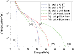
Figure 8. 3D-PIC: spectra of the protons from the contaminant layer at time 173 fs after the beginning of the laser-target interaction. Only particles emitted within 2° from the normal to the rear surface were selected.
Download figure:
Standard image High-resolution imageFigure 9 shows the electron density of DLA foam targets 93 fs after the beginning of the laser-target interaction. Although the electron density becomes more uniform as the interaction takes place, the presence of the DLA foam strongly reduces the difference between linear and circular polarisation. As the DLA foam is characterised by coral-like structures, the propagation of the pulse is strongly determined by the non-uniformities of the density at the micrometric scale length rather than by the pulse self-focusing in a uniform plasma which, on the other hand, would be affected by the polarisation. Moreover, the laser–plasma interaction occurs with a quasi-random set of angles of incidence due to the presence of the clusters, definitively reducing the effect of polarisation. Due to the large computational cost, the simulated DLA foams had to be limited not to consider very small clusters below the grid mesh. The foams obtained with PLD are made of solid density clusters (100s nc) with a smaller radius (∼10 nm) and an occupation factor about five times smaller than the simulated value of 2%. In addition, the DLA model provides an approximate description of the growth properties of PLD foams. Realistic foams with smaller filling factors and a mesoscale structure closer to the real one might further reduce the differences between p- and c-polarisation more closely matching the experimental results.

Figure 9. 3D-PIC: electron density for the DLA foam target 93 fs after the beginning of the laser–target interaction. The laser is p-polarised and arrives from the top-left of the figure. The density  is represented in logarithmic colour scale.
Download figure:
Standard image High-resolution image
Conclusions
The results presented in this paper suggest that the DLT concept may represent a promising solution for the development of laser-driven ion beams. The improvement in the acceleration performances for DLTs with respect to STs can be attributed to a more efficient hot electron generation in the laser–plasma interaction, as the carbon foam allows for the formation of a controlled near-critical plasma in front of the solid foil. Since the maximum ion energies for DLTs do not depend on the laser polarisation, the acceleration performance enhancement cannot be attributed to laser self-focusing, which would instead preserve the polarisation dependence. Therefore, the energy absorption mechanism observed with these targets is substantially different from what was recently reported by Bin et al [17] using carbon nanotube layers on ultra-thin carbon foils.
The best acceleration performances were observed for near-critical foams with a thickness of around 8 μm. The maximum and average proton energies, as well as the number of accelerated protons, are of potential interest for several technological and scientific applications. To this end, DLTs should be adopted in high-repetition-rate configurations to generate ion beams. As far as maximum ion energy is concerned, the reported values are among the highest reported in literature with similar laser parameters [11, 14, 17, 35, 36]. The observed trends and the results of previous simulations [19] suggest that even better results might be obtained with thinner or lower density carbon foams, even though further optimisation in the PLD technique would be required for the production of foams with such improved parameters and with satisfactory spatial uniformity. Moreover, the stability of the acceleration performances with respect to experimental parameters, such as the pulse contrast [21], polarisation and substrate thickness, could allow us to adopt experimental conditions not accessible for other target configurations.
If compared with other advanced target solutions, the robustness of DLTs suggests the compatibility of this target concept with alignment and positioning systems designed for high-repetition-rate laser-driven ion acceleration experiments, such as rotating holders for fast and precise target positioning [37]. The adoption of DLTs in high-repetition-rate systems requires the availability of a reliable technique for foam deposition on large surfaces. PLD provides the possibility of depositing thin foam layers with tunable properties on virtually any substrate and large areas (with diameters >50 mm) and in relatively short deposition times (up to 15 min). In addition, PLD allows the growth of foam layers directly on the substrate resulting in a very good foam-substrate adhesion; this is of crucial importance for target manufacturing.
The results reported in this paper suggest that the adoption of double-layer foam-based targets can represent an appealing solution for the development of a robust, reproducible and flexible acceleration scheme for the production of laser-driven ion beams.
Acknowledgments
The authors wish to thank A Macchi. This work was supported by Institute for Basic Science under IBS–R012–D1 in Korea, and under the framework of international cooperation program managed by National Research Foundation of Korea (NRF-2013K2A1B8074481), and by the Italian National Research Council (Agreement CNR/NRF, Joint Projects 2014-2015). We also acknowledge the support, for the simulations, of PRACE and LISA, for awarding us access to the FERMI resource based in Italy at CINECA, via the projects LSAIL and LAPLAST. The research leading to these results has received funding from the European Research Council Consolidator Grant ENSURE (ERC-2014-CoG No. 647554).