
Abstract
If a compact disc (CD) is placed in front of a plane mirror, its image displays different colours from the ones observed in the real CD. This fact occurs because a CD surface is a diffraction grating which disperses the incident wavelengths. As the object and its image are seen from different viewing angles, the observed colours are not the same, so the image cannot be considered symmetrical to the object. A theoretical discussion on the topic and a simple experimental activity, adequate to secondary school, are presented.
Export citation and abstract BibTeX RIS
An image reflected in a flat mirror shows a fundamental characteristic: it is symmetrical to its object, so the distances between each object point and its equivalent image point are at the same distance from the mirror. This symmetry also results in chromatic equality: if an object area appears yellow, its image also displays this colour. This statement, however, is contradicted if a compact disc (CD) is used as an object: the colours observed in corresponding areas of a CD and its image will not be the same (figure 1).

Figure 1. A CD reflected in a mirror.
Download figure:
Standard image High-resolution imageThis 'symmetry breaking' occurs because a CD is not an ordinary optical object, so the principles of geometrical optics are not adequate to explain this phenomenon. A CD surface is iridescent, since its colour is altered as the viewing angle changes. The seemingly smooth surface of a CD is actually made of closely spaced narrow tracks, which act as a diffraction grating [1, 2] of 625 lines mm−1 on average [3] superimposed on a reflective surface. When a monochromatic light beam impinges perpendicularly on a CD surface, light undergoes reflection and diffraction, resulting in a divergent conical beam (figure 2).

Figure 2. Monochromatic light diffraction (first order maximum) on a CD surface.
Download figure:
Standard image High-resolution imageIf white light (polychromatic) is the input beam on a diffraction grating, chromatic dispersion occurs, because each wavelength λ (colour) has a maximum diffraction at a different angle (θ). Therefore, it is possible to use CDs on a variety of wave optics experiments, e.g. spectra projection [4, 5], homemade spectroscopes [6] or chromatic lenses [7, 8]. If light incidence is perpendicular, the following equation applies:

The track separation on a CD is 1.6 · 10−6 m (d) and wavelengths from about 400 to 700 nm compose the visible light spectrum, so first order diffraction maxima (m = 1) on a CD occur at about 15–25° (figure 3) and second order maxima at about 31–58°1. Red light has the longest wavelength, so its corresponding angle is the largest possible. The colours a person sees on a CD depend on these angles: some areas of the disc, if observed from specific angles, display particular colours (figure 4).

Figure 3. First (m = 1) and second (m = 2) order diffraction maxima angles on a CD surface.
Download figure:
Standard image High-resolution image
Figure 4. An observer looking at a CD surface.
Download figure:
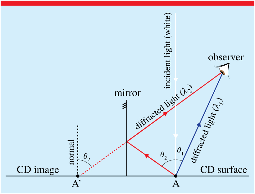
Standard image High-resolution imageWhen a CD is placed in front of a flat mirror, the incident light diffracts and a beam directly reaches the observer (angle θ1). However, another portion of the diffracted light is reflected by the mirror and also reaches the observer (angle θ2). But θ1 ≠ θ2, so the object (A) and its image (A') do not display the same colour (figure 5).

Figure 5. Symmetry breaking explained.
Download figure:
Standard image High-resolution imageIf only the first diffraction maxima are considered, the condition θ1 < θ2 leads to a wavelength λ2 (perceived colour of the image) larger than λ1 (perceived colour of the object). As an example, A could be seen as blue and A' as red (figure 5). However, depending on the observer's location, the first maxima diffraction can be observed on the object while the image displays the second maxima diffraction. In this case, colours are inverted (λ1 > λ2)2. In both cases, the image could not be considered symmetrical to the object.
In order to observe more accurately the colours of the object and its corresponding image, a CD was covered with black paper and only a small square was exposed to white light. As the eye (or camera) moves, one can see the resulting colour changes both in the object and its image (figure 6).

Figure 6. If just a small area of a CD is exposed to white light, colour differences between object and image can be easily identified: blue object and red image (left); red/yellow object and blue image (right).
Download figure:
Standard image High-resolution image
We believe that this simple experimental activity may prove useful when transitioning from geometrical to wave optics in secondary school, since it succeeds in creating a conflict between the prior knowledge of the students about plane mirror images and the observed phenomenon, presenting an important limitation of the light reflection geometrical model.
Footnotes
- 1
Third order diffraction maxima can sometimes be observed on a CD.
- 2
The described condition can be observed if 2λ2 > λ1 > λ2.
Biographies

Jair Lúcio Prados Ribeiro holds a master's degree in Physics Education from Universidade de Brasília. He is currently pursuing a doctorate in Science Education at the same institution, and works as a high school teacher at Colégio Marista de Brasília. His main research interests are optics experimental activities, architecture as a physics teaching tool and the relationship between physics and pop culture.