


Abstract
Taking full advantage of the unique laboratory environment created by the National Ignition Facility (NIF) will require the availability of foam-lined indirect-drive inertial confinement fusion targets. Here, we report on a new approach that enables fabrication of target structures that consist of a thin-walled (<30 µm) ultra-low-density (<30 mg cm−3) hydrocarbon foam film inside a thick-walled, ∼2 mm diameter ablator shell. In contrast to previous work on direct-drive targets that started with the fabrication of foam shells, we use a prefabricated ablator as a mold to cast the foam liner within the shell. This work summarizes crucial components of this new approach, including the aerogel chemistry, filling of the ablator shell with the aerogel precursor solution with nanolitre precision, creating uniform polymer gel coatings inside the ablator capsule, supercritical drying and doping.
Export citation and abstract BibTeX RIS
1. Introduction
New approaches to inertial confinement fusion (ICF) target fabrication need to be developed to build the increasingly complex targets necessary to take full advantage of the unique laboratory environment created by ICF experiments. Foam-lined indirect-drive ICF targets, the subject of this work, are related to spherical foam targets for direct-drive [1–8] and fast-ignition [9–12] fusion experiments that have been developed over the last 20 years. The function of the spherical foam shell in direct-drive fusion targets is to define the shape of the cryogenic deuterium–tritium (DT) fuel layer as first pointed out by Sacks and Darling [13], or to act as a surrogate to simulate the cryogenic fuel layer. This application can tolerate relatively thick (>50 µm) foam shells and, in the case of surrogate targets, high-density foams (180–250 mg cm−3) [1, 4, 8]. Targets containing these mechanically relatively robust foam shells can be fabricated by first fabricating unsupported foam shells using a triple-orifice droplet generator, followed by coating of the dried foam shells with a thin permeation barrier [1, 4, 8].
By contrast, the foam liner in the indirect-drive NIF targets described here will serve as a scaffold to bring dopants in direct contact with the DT fuel for diagnostics and nuclear physics experiments. This function requires thinner and lower-density foam shells in combination with a much thicker ablator shell (table 1). This makes the fabrication of these targets by established methods very difficult if not impossible. For example, the thinnest shells that have been fabricated with the triple-orifice-droplet generator technique had a wall thickness of ∼20 µm [9]. These shells, however, had a diameter of only 500 µm and were made from a higher-density foam formulation. In addition, they were mechanically very sensitive, difficult to dry and showed relatively large deviations from roundness [9].
Table 1. Comparison of ICF targets for direct/indirect drive experiments on OMEGA and NIF.
| Requirements | Direct-drive targets for Omega [1, 4, 8] | Indirect-drive fusion application targets for NIF |
|---|---|---|
| Shell diameter (mm) | 0.8–0.9 | 2 |
| Thickness of the foam shell (μm) | 50–120 | 15–30 |
| Foam density (mg cm−3) | 50–250 | <30 |
| Foam composition | Mostly resorcinol-formaldehyde (RF) based | Ideally pure CHx |
| Permeation barrier/ablator thickness (μm) | 1–5 | 80–150 |
| Permeation barrier/ablator material | Glow discharge polymer (GDP), polyvinylphenol (PVP) | GDP, Be, High-density Carbon (HDC) |
To avoid the challenges that arise from handling free-standing foam shells, we explored a new approach based on using prefabricated ablator shells as molds to cast concentric thin-walled low-density foam shells by sol–gel chemistry. Here, we describe the development of crucial components of this approach, including a new polymer-based sol–gel chemistry, filling of the ablator with the sol–gel precursor solution with nanolitre precision, and a coating technique that is capable of producing uniform coatings on the inside of spherical capsules.
2. Experiment
Dicyclopentadiene (DCPD, C10H12, Aldrich), norbornene (NB, C7H10, 99%, Aldrich) and Grubbs' first generation catalyst, bis(tricyclohexylphosphine)benzylidene ruthenium (IV) dichloride (+97%, Aldrich) were used as received without further purification. As supplied, the DCPD monomer is predominantly endo isomer and contains butylated hydroxytoluene as a stabilizer. Toluene (anhydrous, 99.8%, Aldrich) was bubbled and degassed with nitrogen prior to use. Poly(DCPD-random-NB) or P(DCPD-r-NB) copolymer aerogels were prepared from ring opening metathesis polymerization (ROMP) of DCPD and NB in toluene [14] using a Grubbs' first generation catalyst [14, 15]. The density was controlled by adjusting the concentrations of the DCPD/NB monomer solutions.
High-density carbon (HDC) shells (2 mm ID) [16, 17] with 30–50 µm diameter fill holes (Diamond Materials GmbH, Germany) were used to study the coating behaviour of various foam compositions and densities. To facilitate characterization, we used relatively thin-walled (20–30 µm) and transparent micro-crystalline HDC shells. All coating experiments were performed in a custom-made positioning machine with a cardanic frame as described in [18]. The cardanic frame is made of titanium and allows for rotation up to 20 rpm around two independently driven axes. The system is equipped with computer controlled motors (maxon motors, Switzerland) and can be placed in a furnace with a maximum temperature of 80 °C.
The gel-coated ablator shells then underwent solvent exchange in liquid CO2 at 12 °C and 900 psi in a Polaron critical point dryer to replace the toluene in the gel pores with liquid CO2. Once the toluene was exchanged, the temperature and pressure in the critical point dryer were increased to reach the supercritical regime (∼50 °C and 1600 psi). The pressure was then allowed to slowly decrease to atmospheric pressure while keeping the temperature constant.
The ability of DCPD foams to survive wetting with liquid hydrogen was assessed by ultra-small angle x-ray scattering (USAXS, Advanced Photon Source, sector 32ID) and x-ray microtomography (Beamline 8.3.2 at the Advanced Light Source). The uniformity of wet gel/aerogel coatings was assessed by analysing x-ray micrographs. The position of inner and outer surfaces of the wet gel/foam layer was detected by identifying sharp intensity gradients along a series of radial density profiles extracted from raw images. The weaker contrast of the inner foam surface required averaging over about 10–20 neighbouring intensity profiles over a small angular range (about ±1°). The wet gel/foam layer thickness was then taken as the radius difference between the two gradient maxima, and power mode spectra were obtained by discrete FFT of the thickness versus angle data.
3. Results and discussions
Our approach to fabricate foam-lined indirect-drive fusion targets is schematically illustrated in figure 1. The process requires a suitable sol–gel chemistry and involves the following steps: (1) filling of a prefabricated ablator shell with the desired amount of the sol–gel precursor solution, (2) formation of a smooth and uniform gel layer by deterministic rotation of the capsule during polymerization and (3) doping (if required) and supercritical drying. These components are described in detail in the following sections.

Figure 1. Schematic fabrication process of indirect-drive foam-lined ICF targets: (a) filling of a prefabricated ablator shell with the desired amount of an aerogel precursor solution, (b) formation of a smooth and uniform gel layer by deterministic rotation of the capsule during polymerization and (c) doping and supercritical drying.
Download figure:
Standard image3.1. Sol–gel chemistry
Coating a rotating object with a uniform gel layer requires a sol–gel chemistry that can tolerate a certain amount of shear during gelation. The sol–gel chemistry should be purely hydrocarbon (CHx) based and yield monolithic, low-shrinkage and mechanically robust aerogels with densities as low as 25 mg cm−3 that survive wetting with liquid hydrogen. So far, several pure CHx foam systems have been developed for the triple-orifice droplet generator technique, including divinylbenzene (DVB) [19] and styrene [20] based foams. For the current application, however, these foams have too high densities, too large pores, or shrink too much during supercritical drying. These formulations have also not been tested for their shear resistance. We therefore have decided to further develop a DCPD-based aerogel chemistry [14] that is based on polymerization of DCPD monomers using the ROMP reaction (figure 2).
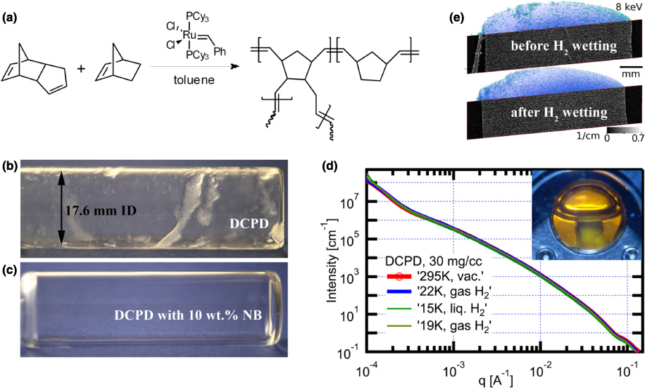
Figure 2. DCPD-based aerogels: (a) schematic diagram of the copolymerization of DCPD and NB with the ROMP reaction catalyzed by a Grubbs' ruthenium complex; (b)–(c) effect of NB addition on uniformity of nominally 180 µm thick gel layers formed in a rotating horizontal glass vial; (c) NB addition (10 wt%) drastically improves the film homogeneity; (d) USAXS for a 30 mg cm−3 DCPD aerogel through stages of filling with liquid H2: vacuum, at ∼22 K exposed to gaseous hydrogen, at 15 K submerged in liquid H2, as depicted in the inset, and then warmed and returned to a gaseous H2 environment; (e) x-ray computed microtomography of identical 30 mg cm−3 DCPD samples, as prepared (top) and after wetting (bottom) with liquid hydrogen. Formation of cracks was not observed.
Download figure:
Standard imageThe ability of the DCPD-based aerogel chemistry to tolerate shear during gelation was first tested by coating experiments in rotating horizontal glass vials (17.6 mm ID, 2 h @ 10 rpm, filled with 500 µl of a 50 mg cm−3 precursor solution). These tests quickly revealed that pure DCPD gels (figure 2(b)) do not form uniform films if gelled under the influence of shear. In an attempt to improve the quality of the gel coatings, we studied the effect of copolymerization with NB, since NB does not have the cross-linking functionality of DCPD (figure 2(a)). These experiments (figure 2(c)) revealed that adding 5–15 wt% NB vastly improves the uniformity of gel films formed in the rotating glass vials. The stabilizing effect of NB can be attributed to the drastic increase in the viscosity at the gel point as detected by dynamic rheology measurements [21]. For example, in the case of 50 mg cm−3 P(DCPD-r-NB) aerogels prepared with 0.2 wt% catalyst, these experiments revealed that both the gelation time and the viscosity at the gel point increase with increasing NB concentration, from ∼10 min and 0.05 Pa s for 0 wt% NB to ∼40 min and 10 Pa s for 10 wt% NB, respectively [21]. The resulting P(DCPD-r-NB) aerogels are monolithic, have densities as low as 25 mg cm−3, and are mechanically strong enough to survive wetting with cryogenic hydrogen as revealed by USAXS and x-ray microtomography (figures 2(d), (e)). Specifically, the absence of wetting/dewetting induced changes in USAXS and x-ray microtomography indicates that the aerogel retains its structure at length scales from ∼5 nm to ∼2 µm (USAXS) and ∼3 µm to ∼1 cm (x-ray microtomography), respectively.
Other promising aerogel chemistries under development and testing for this application include carbon nanotube (CNT) and graphene reinforced resorcinol-formaldehyde (RF) aerogels [22–27]. Reversible wetting with cryogenic hydrogen has been confirmed for all these materials by small angle x-ray scatting (SAXS) experiments.
3.2. Filling
The foam shell thickness is controlled by the volume of the precursor solution filled into the ablator. To achieve the required μm-scale thickness control, we developed a pressure-differential filling method that allows us to reproducibly inject 0.1–1 µl of the precursor solution (for 2 mm diameter shells, this translates into a layer thickness of 10–130 µm) into the ablator. The filling setup is described in detail in figure 3(a). It consists of a small vacuum chamber that contains a vial filled with the precursor solution and a linear feedthrough to which the ablator shell is attached. First, the chamber is slightly underpressurized (20–250 Torr below atmospheric pressure, depending on the desired foam layer thickness) while the capsule is not in contact with the precursor solution. This prevents the formation of air-bubbles attached to the fill hole that is critical for achieving the required reproducibility. The under-pressurized capsule is then submerged in the precursor solution, and filled by re-pressurizing the chamber to atmospheric pressure. Concentration changes by loss of toluene or DCPD/NB through evaporation are minimized by keeping the time between evacuation and re-pressurization as short as possible. The injected volume, as derived from weight gain measurements with the density of toluene under ambient conditions (0.867 g cm−3), increases linearly with the applied pressure differential (with ∼0.01 µl precision) and is almost independent of the hole diameter (figure 3(b)). The linear behaviour can be fit by an expression easily derived from the ideal gas law: ΔV = (Vs/po)Δp where ΔV is the injected volume, Δp is the applied pressure differential and Vs and po are the shell volume (4.2 µl) and standard pressure (760 Torr), respectively.

Figure 3. Capsule filling setup and filling calibration: (a) the filling setup consists of a small vacuum chamber that contains a vial with the aerogel precursor solution and a linear feedthrough to which the ablator shell is attached. To achieve high reproducibility with high accuracy, it is crucial to underpressurize the capsule before submerging it into the precursor solution; (b) injected liquid and corresponding layer thickness versus applied pressure differential. The injected volume, as derived from weight gain measurements, follows the linear behaviour (dashed line) expected from the ideal gas law and is almost independent of the hole diameter.
Download figure:
Standard image3.3. Deterministic layer formation
Coating the inside of a spherical capsule with a smooth and homogeneous film requires precise control over rotation speed and direction. Initial film formation experiments that used the tumbling motion of a capsule in a rotating vial were promising but not reproducible. We therefore decided to build a system that provides a deterministic, continuous change in orientation relative to the gravity vector, thus simulating a true microgravity environment. Such an environment can be realized with two perpendicular and independently driven rotating frames in combination with the computer controlled software (figures 4(a), (b)) [18]. The capsule, filled with a precise amount of the gel precursor solution, is mounted in the centre of rotation, which is where both rotation axes intersect. The capsule is then rotated until gelation is complete, typically for 4–24 h, depending on the aerogel density and the DCPD/NB/catalyst ratio. Independent gelation experiments, performed under stationary conditions in glass vials, have revealed that for a given catalyst concentration, the gel time increases with decreasing aerogel density and DCPD/NB ratio [21].

Figure 4. Foam layer fabrication: (a) coating setup and (b) motion of a random surface point of the rotating sphere; (c) radiograph of a 2 mm HDC capsule (ID) coated with a P(DCPD-r-NB) wet gel layer (50 mg cm−3 DCPD, 20 wt% NB, 0.2 wt% catalyst, filled at ΔP = 102.4 Torr, rotated at 10/14.142 rpm for ∼5 h), and (d) corresponding power mode spectrum of the inner wet gel surface.
Download figure:
Standard imageConcentricity, sphericity and roughness of the resulting gel layer were assessed by x-ray imaging (figures 4(c) and (d)). The sphericity of the foam shells is determined by the sphericity of the diamond molds that have only nm scale deviations [16]. The foam shell thickness non-uniformity is typically dominated by the non-concentricity (mode 1 thickness non-uniformity) of the inner and outer foam shell surface. All non-uniformities with mode numbers higher than two are well below 1 µm. To improve the mode 1 uniformity, we are currently developing a computational fluid dynamics model that will allow us to identify the best combinations of rotational velocity and viscosity for uniform coatings.
To prevent densification of the foam by solvent evaporation through the fill hole during the prolonged coating process, the capsule is placed in a small container that is either filled with saturated vapour of toluene (used as the solvent in the aerogel precursor solutions) or with liquid water. The miscibility of toluene in water is very low (0.5633 ml/1000 ml H2O [28]), and covering the fill hole with water thus effectively blocks the loss of toluene. To avoid periodic patterns of the rotation irrational ratios of the rotational frequencies of the two independently driven frames (typically different by a factor of
 were selected. The critical rotational frequency that is required to coat the inside of the rotating capsule with a smooth, uniform gel layer was estimated analytically and by a computational fluid dynamics model (details will be published elsewhere). In short, the analysis has revealed that the critical rotational velocity scales with the square of the film thickness, and the inverse of the aerogel precursor solution viscosity. For a 2 mm diameter shell and a film thickness of 30 µm, the critical rotational velocity decreases from several hundred to a few rotations per minute as the viscosity of the aerogel precursor solution increases by ∼102, starting at the viscosity of toluene (0.56 cP [29]), as the precursor solution approaches the gel point. Clearly, the viscosity of the aerogel precursor solution at the gel point is of crucial importance for the formation of smooth, uniform films inside the capsule.
3.4. Supercritical drying and doping
The thin foam shell in fusion application targets will be used as a scaffold to bring high-atomic-number (high-Z) dopants in close contact with the DT fuel. Doping with high-Z elements also allows us to non-destructively characterize the low-density aerogel shell inside the thick, high-density ablator using x-ray imaging. Doping can be achieved by either adding functionalized monomers to the polymer solution or by doping of the final gel/aerogel layer. To test the first approach, we added an iodine-functionalized NB monomer, C9H12I2 (full synthetic details for this new monomer will be published elsewhere). The second approach was realized by iodine addition to the remaining C=C double bonds of the DCPD/NB polymer. Iodination was achieved by either placing the ablator shell coated with the wet gel layer for several days in an iodine–toluene solution or by storing the dried shell in an iodine vapour environment. Both approaches were successful, with liquid phase doping resulting in somewhat higher doping levels as judged by the higher contrast in radiographs. We have also demonstrated that the dried foam shell can be uniformly doped using atomic layer deposition [30]. Finally, the wet gel layer was supercritically dried by direct solvent exchange with carbon dioxide. A representative radiograph of an iodine-doped foam shell inside a diamond ablator is shown in figure 5.

Figure 5. (a) Radiograph of a 2 mm diamond capsule with an iodine-doped P(DCPD-r-NB) foam layer (25 mg cm−3 DCPD, 15 wt% NB, 0.2 wt% catalyst, filled with Δp = 104.5 Torr, and coated at 10/14.142 rpm for 17 h). The feature in the lower left corner of the shell is glue residue on the outside of the ablator shell; (b) two representative power spectra of the inner foam surface summarizing the currently achieved foam shell uniformity.
Download figure:
Standard image4. Summary
In summary, we have demonstrated the feasibility of all process steps required to fabricate foam-lined indirect-drive ignition targets based on spin-coating the inside of prefabricated ablator shells with aerogel precursor solutions. We have developed a non-shrinking 25 mg cm−3 CHx -based polymer aerogel that is robust enough to survive wetting with liquid H2 and that can be spin-coated. We also developed a system that allows the fabrication of uniform gel layers inside spherical capsules and demonstrated both doping and drying of gel layers formed inside the ablator shell. All process steps seem to be scalable, and the reproducibility of both filling and gel layer formation is good. Currently, our process yield is limited by foam collapse during supercritical drying indicating issues with solvent exchange, and mode 1 thickness non-uniformities (non-concentricity). The first problem is addressed by developing a modified solvent exchange protocol. To explore the origin of the mode 1 thickness non-uniformities, we are currently developing a computational fluid dynamics model to guide our coating parameter selection (rotational velocity and gel precursor solution viscosity).
Beyond diagnostics and nuclear physics applications, foam-lined targets with thicker foam layers also have the potential to facilitate the fabrication of smooth and homogeneous DT fuel layers for indirect-drive ICF experiments [13]. Future work will be focused on further improving the uniformity of the foam shells, increasing the yield of the process and exploring alternative aerogel chemistries.
Acknowledgments
This work performed under the auspices of the US Department of Energy by Lawrence Livermore National Laboratory under Contract DE-AC52-07NA27344. We would like to thank C. Wild and E. Woerner from Diamond Materials GmbH, Germany, for providing the diamond capsules. The Advanced Light Source and Advanced Photon source are supported by the US Department of Energy, Office of Science, Basic Energy Sciences, under contracts DE-AC02-05CH11231 and DE-AC02-06CH11357, respectively. TW thanks A. MacDowell and D. Parkinson (ALS), and J. Ilavsky and A. Deriy (APS) for their support.