


ABSTRACT
The equations of motion, modified by the relativistic correction to a rotating inclined magnetic field, are discussed. It is shown that the magnetic moment would precess under the influence of the retardation torques identifiable by several higher-order terms in the relativistic correction. The observed cyclical behaviors from the clock-like pulse-emitting pulsars reported by many researchers are likely to be the consequences of the retardation effect produced by an inclined magnetic moment of a spinning body. The results, which come from the study of two independently rotating magnetic moments, are in agreement with the observed pulsar data for the pulsar PSR B1828–11. These electromagnetic driving forces are presented for further exploration and discussion.
Export citation and abstract BibTeX RIS
1. INTRODUCTION
Recently, many researchers (Stairs et al. 2000; Livingstone et al. 2005; Shabanova et al. 2001; Scott et al. 2003) have observed that there are cyclical behaviors buried in the pulsar's timing data collected over many years. It is found that these features are likely to be associated with a precession (Akgün et al. 2006; Link & Epstein 2001; Haberl et al. 2006). A relativistic correction to the motion discussed below would result in a precession of the magnetic poles. The relativistic correction to the movement of magnetic poles can be identified by several higher-order retardation terms produced from an inclined magnetic moment of a rotating body. A simple illustration is shown in Figure 1, where a magnetic dipole moment M of a rotating body is initially inclined at an angle Θ with respect to the angular momentum L of the rotating body.

Figure 1. Magnetic moment M of a rotating body.
Download figure:
Standard image High-resolution image2. THE EQUATIONS OF MOTION
A dynamic state is in its lowest energy if the angle Θ between the magnetic moment M and the angular momentum L of the rotating body vanishes. It will be shown that without a countering torque, the angle Θ would decrease with time, resulting in an oscillatory motion determined by a retardation torque τx to be illustrated in the example below.
We recall now that the general expression for a magnetic field B at a point r1 at a time t produced by a current density j at some other point r2 at some other time t' is given by (Panofsky & Phillips 1962)
where the retarded time, t' = t − r12/c and r12 = r1 − r2.
It is known that the photon travels at a finite speed c. The variation in the magnetic field, i.e., the retardation field due to the non-instantaneous process shown in Equation (1) arises when the magnetic moment M is rotating at an angle to the rotation axis of an object.
The electromagnetic field produced at the retarded time t' can always be decomposed into a series of power-ordered terms. The first-order term in the calculation (Good & Ng 1985) has been identified to be the Biot–Savart term evaluated at the present time t, i.e., instantaneously. The higher-order terms are the relativistic corrections to the behaviors of the magnetic moment M which is inclined at an angle to the axis of rotation.
The power-ordered terms are identified according to the power of the velocity v in the form v/c, where v is r × Ω and Ω is the angular velocity of a rotating body. For example, a second-order term refers to a term having v2/c2, etc.
The second-order term of the torques produced by the retarded magnetic field is shown in Equation (2), and the third-order term has two components, τy (Equation (3)) and a well-known spin-down torque τz (Michel & Goldwire 1970; Deutsch 1955), where M is the magnetic moment of a rotating body having a radius a:
As shown in Figure 2, the effect of τy along the y-axis is to rotate the magnetic moment M in an anticlockwise direction in the z–x plane. When M makes an infinitely small rotation of an angle δθ in the z–x plane, the new torque τy, which should always be contained in the same plane as L and M, will point in a new direction, which is now out of the y–z plane. The y-axis rotates about the z-axis in a way that the y-axis is in the same plane as M and L, and τyalways points in the y-direction. The rotation of the y-axis about the z-axis is characterized by an angle ϕ' in Figure 2.
Figure 2. Movement of the magnetic moment M in a coordinate system.
Download figure:
Standard image High-resolution imageThe torque τycauses M to rotate along a vertical loop, Vloop in Figure 2, which is symmetric about the rotating y-axis. Figure 3, produced from the numerical integration for the loop Vloop, shows the periodic nature of the behavior of the angle θ, the changing angular separation between M and L, for different initial values of Θi. The angle Θi is the initial angular separation between M and L, when M and L are instantaneously at rest relative to each other.
Figure 3. Variation of θ under the torque τy.
Download figure:
Standard image High-resolution imageThe time, T, when t/T = 1.0, is a period for the movement of the magnetic pole to complete a cycle, i.e., a loop in the Vloop shown in Figure 2. The time variable t is a fraction of T in the calculation of the points in Figure 3.
We discuss in more detail the effect of the second-order term τ(2)x to the orientation of the magnetic moment M. For the torque τ(2)xpointing along the x-direction as shown in Figure 2, Equation (2) implies that M is executing a two-dimensional oscillatory motion about L in the y–z plane. Moreover, if Θ is small, τ(2)x ∝ Θ, the motion becomes a well-known classical harmonic motion. Since the relative strength of the third-order term is approximately a factor of aΩ/c smaller than the second-order term, the relative rate of change in the angle Θ caused by the second-order term would be a factor of about c/aΩ higher than the third-order term. The combined effect of these torques, τ(2)x and τ(3)y, is that the magnetic moment M oscillates in a two-dimensional plane, while at the same time, M also moves with a much smaller amplitude along a path determined by the points on the Vloop in a three-dimensional space, with the loop Vloop oscillating about the origin O.
3. PRECESSION OF PULSARS
Recent studies on timing residuals from some pulsars have indicated that there are some puzzling cyclical behaviors buried in the streaming pulses collected over the years. Stairs et al. (2000) have concluded in their spectral analysis from their collection of data spanning over 13 years that periodicities of about 1000, 500, and 250 days have appeared in the timing data from the pulse-emitting pulsar PSR B1828–11. The pulsar has a characteristic age of 0.11 Myr and a rotational period of 405 ms. The variation in the pulse shape is highly correlated with the derivatives of the period residual of the pulsar, strongly suggesting that there is a precessing motion while rotating and producing repetitive pulses.
Livingstone et al. (2005) and Shabanova et al. (2001) have reported similar cyclical behaviors for pulsars PSR B1509–58 and PSR B1642–03 from their respective data sets of about 21 years and 30 years. For PSR B1642–03, the timing amplitude has varied between 15 and 80 ms from its average long-term period of 388 ms. The maximum deviation from the average period had occurred between 3 and 7 years.
Scott et al. (2003) have found that the famous 30 Hz isolated Crab pulsar has a periodic component of about 568 ± 10 days in the timing data. They have evaluated that a companion mass of M ⩾ 3.2 M⊕ would have been required to cause the Crab pulsar to precess to show such a cyclical behavior in their observed data. The Crab pulsar is assumed to have a mass of about 1.4 M☉ in their evaluation.
It is generally believed that any precession caused by the vortices in the superfluid interior of the pulsars would have been damped out on a timescale of several hundreds to thousands of precession periods (Sedrakian et al. 1999; Shaham 1977). The irregular motion would have already disappeared, given the known observed ages and the spinning rate of the pulsars. We discuss below the equations of motion produced by the retardation torque which is of an electromagnetic origin that would result in a precessing motion.
We adopt here the convention that the magnetic moment M is rotating relative to the spin axis L as shown in Figure 5(a). The magnetic moment M in reality does not necessarily pass through the center O of a spinning object. In Figure 5(a), OA, AB, and BC are the magnetic moments. OA and AB are in the same plane as YOZ', but BC is out of the planar surface formed by YOZ'. The magnetic moment M is a combined vector of AB and BC. The vector OC would have been an idealized vector passing through the center O and rotating about the Z' axis. BC is an off-plane component of the magnetic moment M. As discussed in the sections above, the angle α between BC and the Z'' axis would yield a second-order retardation effect. This effect would result in an oscillatory motion about the Z'' axis.
The magnetic moment M, as explained in Figure 5(a) above, is therefore moving in a cyclical motion with a varied angle of inclination, when the magnetic moment M is shifted and it does not coincide with the center of a spinning body. The period of precession depends on the amplitude BC and the angle α. The precession due to the off-center magnetic field is an extra feature of the oscillatory motion, which is already described in the sections above.
The variation of the angle Θ between a pulsar's rotational and magnetic axes has been proposed to be a possible ground for the observed persistent increases in the spin-down rates of the Crab and Vela pulsars (Link & Epstein 1997). Lyne & Manchester (1988) have inferred from the analysis in the pulse shapes of the beams of pulsars that there are some systematic changes in the angle Θ. The observation of the variation in the inclined angle Θ is consistent with the above discussion that the angle Θ would continue to vary under the influences of the second-order retardation torque. The braking index of a pulsar would inevitably be influenced by the variation in the inclined angle Θ coming from the second-order retardation torque.
The vector BC in Figure 5(a), indirectly representing an off-center component of the magnetic moment, contributes an additional degree of freedom to an already complicated picture of motion of the magnetic pole discussed in the sections above.
4. ROTATION MATRIX, EULER EQUATION, AND MULTIPLE MAGNETIC MOMENTS
The magnetic moment M, under the influence of the torque τy, is rotated by an angle ψ about the y-axis (Figure 2). The transformation matrix between the x, y, z coordinate system and the new x''y''z'' system is
Thus, we have cos θ'' = cos ψcos θ. As viewed from the z-axis, θ'' = θ + Δθ and ωy = dψ/dt. We replace ψ by Δψ and expand the equation into a power series, and we get
For an infinitesimal change Δψ in the angle ψ by the torque τy, there is a change Δθ in the polar angle θ, as viewed from the rotation axis, where the  is pointing.
We have,  and ωx = dθ/dt. Using integration by parts, and for a spherical object, where I1 = I2 = I3,
where c1 and k1 = 4M2/5/c2/Ix/a are constants.
The results for a spherical object and an oblate object are plotted in Figure 4. The Euler equations for a non-spherical object have been considered by others. The derivation and the results are detailed in the works of Melatos (1999, 2000), Goldreich (1970), and Davis & Goldstein (1970).

Figure 4. Spin-down curve due to the precessing magnetic moment M.
Download figure:
Standard image High-resolution imageIt is noted that the mathematical representation for Equations (2)–(4) and their transformation matrices has been employed and discussed in detail by Melatos (1999). The numerical results shown in Figure 4 are obtained by using the formalism and a rotation matrix described above.
We now consider a case in which the total magnetic moment  is a vector sum of two magnetic moments,
  and
and  , as shown in Figure 5(b). The plots are shown in Figures 6–8. The ratio in the amplitudes of
  and
and  is 16 in the plots. The ratio of the periods for
  and
and  is about 1:25. The magnetic moments,
  and
and  , are, respectively, inclining initially at the angles of 10° and 60° to the rotation axis. The solid circles shown in Figures 6 and 7 and the curve drawn with error bars in Figure 8 are the data taken from Stairs et al. (2000), for the pulsar PSR B1828–11.

Figure 5. (a) Offset from the center O. (b) Multiple magnetic moments.
Download figure:
Standard image High-resolution image
Figure 6. Changes to the period illustrate the effect from a precessing  . The data in solid circles are taken from Stairs et al. (2000) for the pulsar PSR B1828–11.
Download figure:
Standard image High-resolution image
Figure 7. Time derivative of the period residual from the precession of  . The data in solid circles are taken from Stairs et al. (2000) for the pulsar PSR B1828–11.
Download figure:
Standard image High-resolution image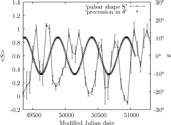
Figure 8. Precession of the magnetic moment  and the shape parameter 〈S〉 from Stairs et al. (2000).
Download figure:
Standard image High-resolution image
The cyclic behaviors implied from the plot of the time derivative of the period residual in Figure 7 are about 260 days and 520 days. This is consistent with the estimates of 250 and 500 days provided by Stairs et al. (2000).
Most of the pulsars are known to have their unique signatures. They are often identified by the pulse profiles of the arriving pulses. The pulse profile is usually characterized by the pulse width, pulse shape, and their relative inter-pulse positions.
The strong correlation between the pulse width and the changes in the period of the pulses (Stairs et al. 2000) suggests that the magnetic moment  has swept through different regions of the star. Each region for the eventual electromagnetic radiation may be identified by an effective cross-sectional area for radiation, and the magnetic field density for the eventual pulse width and the signal strength we are seeing. The thickness, the composition, the magnetic properties of the crust of the star in proximity to the emission region, and the geometry of the star's irregular surface may affect the magnetic field strength and the geometry of the emission region. More data would help to establish the relationship between the change in the location of the emission region and the pulse width of the arriving pulses.
Starting from the Modified Julian Date of 49,500 as shown in Figure 8, the pulses of narrower width are seen when the magnetic moment,  , is rotating from an inclined angle of θ = 0° to θ = −8°. There is a peak in the corresponding time interval in the pulse-shape parameter 〈S〉. The shape parameter 〈S〉 is defined as S = AN/(AN + AW) in the paper by Stairs et al. (2000), where AN and AW are the fitted heights of the narrower and wider standard profiles. The solid lines with the error bars are the data taken from Stairs et al. (2000).
Upon returning from its extreme position, i.e., θ = −10° in a periodic cycle, the magnetic moment  again passes through the same region, from θ = −8° to θ = 0°. The shape parameter 〈S〉 in the corresponding range again re-approaches the value of 1. There are two peaks in the shape parameter of Figure 8 that are close to each other during a periodic cycle in the precessing motion of the magnetic moment
  (i.e., the inclined angle θ is varying within the range ±10° in Figure 8).
The precession of the magnetic moment  , which is a vector sum of
  and
and  , is different from the works done by Link & Epstein (2001). They have proposed that the periodic behavior seen in the pulse timing from the pulsar PSR B1828–11 is due to the precession of the rigid crust of the star. They have found that the star's magnetic dipole moment is nearly orthogonal to its symmetry axis and the star's crust wobbles at about ≃3°. It is noted that there are deviations on the right-hand side of the curve in Figure 8, which may indicate a glitch or other mechanism that has perturbed its regular motion.
5. THE BRAKING INDEX
The traditional (observed) braking index of a pulsar is usually defined by the acceleration in the angular velocity,  . It leads to the expression,
  .
.
Here, we define an index, n, so that  . By a direct differentiation and substitution, we obtain, where f'(θ) = df/dθ,
For n = 3 and f(θ) = sin2θ,
A good approximation is obtained when the retardation torques are included and Equation (7) is used:
where c1 and k = 4M2/5/c2/Ix/a are constants. The inclined angle θ, its time derivative, and the constants may be inferred from the variation of the observed braking index nobs relative to the spin-down effect over a long period of time.
Livingstone et al. (2006) have found that the braking index of a young pulsar PSR J1846–0258 has a value of n = 2.65 ± 0.01. The observed value of n is significantly less than the expected value of 3 from a pure magnetic dipole radiation. As noted in Equation (9) (or Equation (10)), it is possible to have a value which is less than 3, when the inclined angle θ varies during a precessing motion of the magnetic moment  under the influence of the retardation torque. In a model developed by Melatos (1997), it is possible to have the observed braking index, nobs < 3, when an inner magnetosphere is corotating with a non-point dipole.
6. DISCUSSION
The long-period cyclic behaviors embedded in the observed pulse signals, i.e., the observed period Pc of each cyclic feature, Pc≫ a rotational (spinning) period of a pulsar, have been reported as cited above. It would be interesting to find out if a short-period precession can be observed in a pulsar having a non-core-center magnetic field. The short-period cyclic behavior in the pulse profiles, with a time constant comparable to the spin period, is different from some other long-period precession effects, such as the spin–orbit interaction, the general relativistic effects like the geodetic precession and the periastron precession, etc. The periodicities of the various precessions emanating from different physical causes are usually different. An observed pulsar's signal is a combined result of several superimposing precession effects.
In a binary star system, the line-of-sight angle of the hot spot generating the pulses would appear to come from different locations in the sky during a pulsar's orbital motion. The short-period cyclic behaviors are buried in the second and third derivative of the spin rate ν (i.e.,  ) of the orbiting pulsar. The characteristics and the changes in the pulse-shape parameters at different orbital phases of the pulsar would give further insight into the motion of the orbiting pulsar.
The pulse-shape parameters (pulse width and the pulse spectrum) of arriving pulses have, in the past, been shown to imply a long-period precession. An active pursue of other precession effects hidden in the pulse signals would continue to enrich our knowledge about the pulsars.
Several models emulating a precession scenario have been presented to explain the data accumulated from the pulsar PSR 1828–11 (Link & Epstein 2001; Akgün et al. 2006) and the pulsar RX J0720.9–3125 (Haberl et al. 2006). Their findings, together with a study of the variation in the spin-down parameters (Urama et al. 2006), lend strong support to the precession interpretation in the pulsars.
Attempts have been made to explain the precession. It is believed, in a published research note by Link (2006), that a possible high precession frequency from creeping neutron vortices is incompatible with the long-period precession seen in the pulsars. Others have tried to explain the precession in terms of a crust–core coupling in the pulsar.
The discussion on electromagnetic torques above indicates that the inclined angle θ in Figure 2 would change under the influence of a y-component torque τy of Equation (3). The torque τy is causing an infinitesimal change in θ, while at the same time, the pulsar is undergoing a long-period precession (a periodic variation in θ) caused by the second-order x-component torque τx of Equation (2). The changes in θ under the torque τx cannot possibly be greater than 90°, i.e., Δθ < 90°. As shown in Figure 3, the range, 0°–180°, in which the inclined angle θ could possibly traverse under the action of the torque τy, is consistent with the spin-down study of 131 radio pulsars (Urama et al. 2006), when it is found that there are nearly equal numbers of pulsars having  as have
  . There is no preference to the angle of inclination θ in the system when the inclined angle θ in Figure 2 either has a value from 0° to 90° or in a range from 90° to 180°.
The y-component torque τy of Equation (3) described above would have caused the magnetic moment M to move between 0° and 180° (Figure 3) over a long-term pulsar evolution (i.e., t≫ pulsar's period). It is noted that the pulsars' characteristic ages are 103–108 years in the 131 radio pulsars survey (Urama et al. 2006). The sample of 131 radio pulsars with ages over such a vast extended range may be considered sufficiently representative in the statistical study of long-term pulsar evolution.
The spin-down torque τz is proportional to  (Equation (4)), and the derivative of
  . A simple interpretation to the observed equal number of pulsars on opposing side of the sign in
  (the second derivative of the spin rate ν) is to say that there is an equal number of pulsars having an inclined angle of θ from 0°to90°, as well as θ from 90°to180°.
In the absence of a y-component torque τy, the observed equal number of pulsars would have implied that it would be equally probable to have an inclined angle Θ greater than 90° when a fast spinning pulsar is initially born. It would suggest that the inclined angle Θ of the corotating source producing the magnetic field could have an equal chance to be greater than 90°. In other words, if τy is non-existent in our picture, it would be unusual to admit a symmetry that it is equally probable for a distribution of pulsars to have a very large initial angle of inclination Θ>90° when a pulsar is born.
The equation of motion due to the relativistic correction described above for an inclined rotating magnetic field is independent of the mechanisms that produce the magnetic field. The laws of electrodynamics are applicable to an inclined loop of induced electric current flowing in the fluid. The inclined loop of induced electric current would be similarly influenced by the torques produced by the retarded magnetic field, when the magnetic field B is rotating at an angle Θ to the axis of rotation.
The perturbation from the cooling of the cores and the toroidal tidal effect from a quake-like event may add to the complication in the dynamic nature of the fluid flowing in the inner core of the rotating body.
The author very much appreciates some very valuable discussion and help from Prof. James Lattimer. James has raised a possibility in the detection of the precession through a binary star system. The author thanks Professor Bob McCarthy, Professor Robert Shrock, and Professor Michael Rijssenbeek for their constructive criticism and helpful advice on this manuscript.