


Abstract
A new generation of ultra-high intensity femtosecond petawatt- and above-class lasers requires new approaches to wavefront corrections. New challenges for adaptive optics consist in overcoming the constraints of potentially bigger diameters, larger amplitude aberrations, faster optics, higher risk of damaging optical components and faster and easier maintenance. Here we present a new technology of a mechanical deformable mirror, which has a large stroke, high temporal stability, low hysteresis, no print-through effect, easy, safe and fast maintenance and an operating frequency up to 10 Hz. We propose the full correction of the final focal spot in the target chamber by a combination of a standard adaptive optics system, a simple focal plane camera and a phase retrieval correction process. We test the reliability of the correction system in terms of intensity variation and wavefront stability. We further verify correction robustness of the method on a large spectral bandwidth and finally perform a focal spot correction on a terawatt laser system in both low and high-power regimes.
Export citation and abstract BibTeX RIS
| N. Varkentina, G. Dovillaire, J. Legrand, G. Beaugrand, I. Stefanon, P. Treimany, X. Levecq Imagine Optic, 18 rue Charles de Gaulle, 91400 Orsay, France |
| e-mail: nvarkentina@imagine-optic.com |
1. Introduction
Recent progress achieved at ultra-high intensity laser facilities has attracted scientists from numerous research fields to potentially new laser applications such as warm-dense matter physics [1], astrophysics and cosmology [2], controlled nuclear fusion [3], generation of MeV (GeV) laser proton beams for treatment [4] and imaging [5,6], etc. The generation of high energy particles (electrons, protons, charged ions, neutrons) and the whole range of irradiation (from soft X-rays to gamma rays) has become possible due to the interaction of highly focused, high intensity laser beams with solid or gas targets. Therefore, a lot of effort has been made to develop high intensity (1018 – 1023 W cm−2), petawatt lasers.
To achieve a petawatt (PW) laser power in laser facilities one requires to develop new technologies based on the loss compensation. It is important to correct wavefront aberrations, caused by a large number of optical elements in multiple amplification and compression stages inside the laser. The interaction chamber also contains optical elements, which may result in further beam distortions and thus provoke more intensity loss. In particular, in such applications as ion acceleration, warm-dense matter physics and controlled nuclear fusion, the quality of the focused beam is of the primary importance because laser beam intensity will define the energy of accelerated particles [7–9] or the threshold of initiation of the fusion process.
To experimentally ensure the highest achievable intensity, one has to accurately control both the spectral phase to produce the shortest pulse and the spatial phase to provide the smallest focused spot in the interaction chamber. Nevertheless, it is extremely difficult to experimentally reach an aberration-free focal spot without the use of adaptive optics [10]. To generate a diffraction-limited focused beam one needs to control a number of factors in the optical setup. To name a few, it is important to suppress and control the wavefront distortions caused by a large number of optical elements and mechanical constrains on large optical elements (static, no time variation), thermal effects in amplifier glass (varying on a time-scale of minutes) and aberrations in laser amplification and compression chains as well as aberrations due to the final focusing in the interaction chamber.
The spatial phase could be efficiently corrected and controlled using adaptive optics. The typical system usually contains a wavefront sensor to measure the spatial phase and a deformable mirror to correct it. For high-power laser chains at low repetition rates (below 0.1 Hz) it now becomes standard to place adaptive optics at the output of a laser chain (in front of or behind the compressor) [10–12].
In this paper, we will define spatial phase optimisation strategies for ultra-high intensity and high-repetition rate (few Hz) laser beams. At first we will discuss recent developments for laser installations with high repetition rates. In this case the thermal effects may be more severe (but still slowly varying) and high intensity lasers require more extreme focusing. The deformable mirror (DM) must be able to correct larger aberrations, to handle high average and high peak laser power on sub-second time scales on a large clear aperture (550 mm or more).
In the second part of this paper we will describe a new generation of our mechanical DM where we integrated those characteristics. The newly designed actuators bring such advantages as better mechanical efficiency and better thermal stability even at 10 Hz. Also variability in beam diameter (from 16 mm to more than 500 mm) and in angle of incidence (from 0° to 45°) allows us to achieve good correction results. Easier and safer DM maintenance have also been proven by replaceable mechanical actuators.
In the third part of the paper we will pay particular attention to the correction of the end-of-chain aberrations by implementing a simple wavefront control strategy. This direct and automated method uses a standard focal spot camera and phase retrieval algorithms [13,14] for direct measurement and correction of the wavefront on the focal spot. The quality of the focal spot is characterised by the Strehl ratio, obtained for both low-energy pulsed beams and full-energy shots. This procedure does not require additional hardware or any manual operation and it has been successfully used for proton generation optimisation. Finally, in the fourth part, we will discuss and conclude on the future developments of the wavefront control for extreme intensity light sources.
2. Results
2.1. Mechanical deformable mirror for a high-power laser
Mechanical deformable mirrors, developed for high-power laser applications, have a number of advantages over other deformable mirrors, such as bimorph, MEMS, magnetic, etc. To name a few, they include the possibility to integrate high-power coatings with a high laser-induced damage threshold (even for large diameter beams), as well as the high temporal stability, total immunity to electromagnetic perturbations, large dynamic range and low hysteresis. Moreover, the residual aberrations on the deformable mirror feature low or no print-through effect, which is a residual deformation due to the finite size of actuators and spacing between them. It can be visible on the membrane surface when approaching the flat mirror shape. An example of a mechanical deformable mirror is presented in Fig. 1. The technology of a mechanical deformable mirror is based on mechanical actuators. Macroscopic motion of mechanical parts inside the actuator sets the force on the back of the mirror surface, which in turn on a nanometric or micrometric scale modifies the shape of the reflective surface.
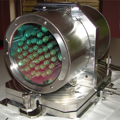
Figure 1. ILAO Star vacuum-compatible mechanical deformable mirror with a high-power dielectric coating.
Download figure:
Standard imageFor high-power laser applications, the deformable mirror is usually not controlled during high-power shots to avoid any shape modification, which could result in important modification of the location of the focused spot or in hot spots that could damage some parts of the laser installation or expensive optics (for example, diffraction gratings). Stability of the wavefront correction is therefore critical for the focal spot correction quality. The technology of mechanical deformable mirrors is intrinsically extremely stable: electric power is only needed to move the macroscopic parts inside the actuators. Then, it is not necessary to hold an electric voltage or current on the actuator to maintain the force applied to the mirror. Mirror shape remains perfectly stable over the time even if the electric power is turned off or the controller is unplugged. Figure 2 shows the results of the mirror's stability over time. As one can see, the variation of the wavefront is less than 10 nm rms (root mean square) in 13 hours without any voltage control. The correction quality is maintained without a closed-loop adaptive optics correction running continuously and the deformable mirror becomes almost a passive component (stable in time). This also makes the mirror highly insensitive to an electrostatic discharge or perturbation as these perturbations never carry enough power needed to move mechanical parts inside actuators.
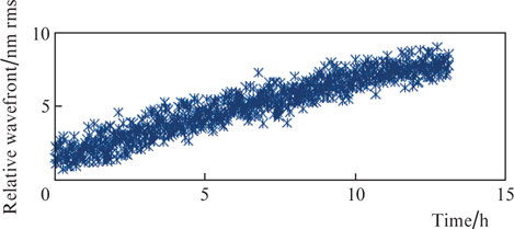
Figure 2. Time stability of the ILAO Star deformable mirror after the power is switched off.
Download figure:
Standard imageIn a laboratory environment with controlled air turbulence or in big laser facilities with vacuum pipes for beam-guiding, the wavefront stability after correction using a mechanical deformable mirror could be below 5 nm rms. Moreover, the mechanical deformable mirror with no print-through effect will avoid hotspot propagation. The best active flat correction could reach 5 nm on the surface as it is shown in Fig. 3a. Using our new patented actuators [15] one can reach up to 100 μm PtV (peak to valley) for low order aberrations (focus and both astigmatisms), up to 30 μm PtV for coma and trefoil and 9 μm PtV for the third order spherical aberration. When correcting large deformations, higher than 21 μm PtV, the quality of wavefront correction is on the order of 17 nm rms (see Figs 3b and 3c). This large dynamic range of actuator displacement allows aberrations caused by severe thermal effects and extreme focusing to be corrected. In addition, the implementation of novel actuators into the DM allows us to increase the speed of correction up to 10 Hz [15].

Figure 3. Wavefront measurement of the ILAO Star mirror: (a) active flat correction (10 nm rms); (b) large deformation (> 21 μm PtV, including 1.96 μm PtV of spherical aberration); (c) good quality corrected wavefront with a residual aberration of 17 nm rms.
Download figure:
Standard imageThe typical adaptive optics correction strategy is to use a beam leakage and to measure its wavefront using a wavefront sensor. However, this strategy ensures the laser beam to be aberration-free only at the location of the wavefront sensor. Aberrations induced by the optical elements located downstream of the wavefront sensor, for instance focusing optics, are not measured and therefore are not corrected by an adaptive optics loop. These aberrations may contribute to the degradation of the focal spot at the end of the optical chain. In order to get the highest possible intensity on the target, an aberration-free wavefront in the interaction chamber is required. But this does not mean that we have an aberration-free wavefront at the wavefront sensor location.
2.2. Adaptive optics implementation for the end-of-chain aberration correction
Generally, as is shown in Fig. 4, in high-power laser chains a deformable mirror is placed after the laser pulse compression stage. Downstream of the deformable mirror a leakage mirror is implemented, which selects a small fraction of the main beam for the wavefront measurement by the wavefront sensor. This optical path may include lenses that adapt the beam to the size of the wavefront sensor and make the optical conjugation between the deformable mirror and the wavefront sensor. To cancel wavefront distortions the deformable mirror and the wavefront sensor are operated in a closed-loop regime. Thus, an almost perfectly flat wavefront is obtained in this part of the optical setup. This type of wavefront correction is present in numerous high-power laser installations such as QST (National Institutes for Quantum and Radiological Science and Technology, Japan), CEA Saclay (Le Commissariat à l'énergie atomique et aux énergies alternatives, France), ELI Beamlines (Czech Republic), synchrotron installations SLAC (Stanford, USA) and DESY (Dortmund, Germany) and many others.
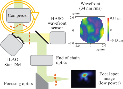
Figure 4. Scheme of a typical adaptive optics implementation in high-power laser chains. The image of the laser beam at the focal plane at a low laser power (lower right) and an example of the wavefront measured using the HASO wavefront sensor (upper right) at the CELIA laboratory (Bordeaux, France). Dashed lines show the shape of the wavefront.
Download figure:
Standard imageFurthermore, there are several optical elements on the main path of the laser beam (mainly mirrors) to guide and focus it. All these optical elements can introduce some aberrations, which explain why the best wavefront on the wavefront sensor plane does not give the best focal spot. These aberrations are called differential aberrations and it is important to note that these aberrations are static, not changing in time. Nevertheless, these aberrations at the end of the laser chain are not measured by the wavefront sensor and thus are not corrected by the deformable mirror [12]. An example of the wavefront measurement at the standard wavefront sensor position (at the end of the compression chain) at the installation of the CELIA laboratory (Bordeaux, France) is shown in Fig. 4. As one can see, the residual wavefront error is only 34 nm. Even if the value of the residual wavefront error is quite small (perfect correction at the level of the wavefront sensor), in this experiment the measured Strehl ratio of the focused laser beam equals only 0.6.
A number of different iterative methods have already been developed in astronomy and aerospace to correct the end-of-chain aberrations [16,17]. Nevertheless, these methods are not adapted to single-mode measurements and are used to correct aberrations for a wide bandwidth sources. Moreover, the intensity profile could be known for high-power laser applications during the measurement procedure. It was shown by Sheldakova et al. [18–20] that using genetic and hill-climbing algorithms one could correct high-power installations while coupling a bimorph mirror and M2-meter. Unfortunately, these algorithms are converging much slower and the final result of the hill-climbing algorithm is strongly dependent on the initial surface deformation of the mirror (starting point). Frequently these algorithms find the local minimum and get stuck there, which means that the optimal shape of the deformable mirror is never attained. Moreover these iterative methods demand at least several tens of iterations. The algorithm converges faster if the starting point is closer to the final solution [18].
The method presented here, phase retrieval adaptive optics (Pharao), is a direct method, which is adapted to laser applications. The Pharao correction method is comprised of two steps: 1) correction of aberrations in closed-loop regime and 2) estimation of differential aberrations using the phase retrieval algorithm [13,14]. The main idea of the method is to collect at least one image, which differs from the focused one by a known phase variation. This phase diversity algorithm aims to insure the uniqueness of the solution on the relationship between the point spread function (PSF) and the aberrated phase and thus to determine the differential aberrations. In our case, to perform the second step of the correction, a CCD camera at the focal spot location is used. In order to get enough information to calculate differential aberrations, three images of the focal spot are acquired by a CCD with the three different defocuses: one image in focus, one image with a positive defocus and one with a negative defocus.
Then, use is made of the following formalism taking into account isoplanetism hypothesis [21]:

where r is a two-dimensional vector in the image plane; i(r) is the image, which is the result of the convolution of the PSF(r) at the observation plane and the object O(r); and n(r) is the noise.
The PSF of the focused image has the form:

where F−1 is the inverse Fourier transform, u is a two-dimensional vector in the pupil plane, P(u) is the aperture function, and φ(u) is the unknown phase.
Mathematically, the aberrated phase could be expressed in terms of Zernike polynomials zk(u):
where ak is the unknown aberration coefficients.
The PSF of defocus aberration is defined:

where φd(x, y) is the known phase.
We minimise the error by comparing the Fourier transform of the image F(PSFi) and the Fourier transform of the reconstructed image using Zernike polynomials F(PSFZ) such as F(PSFi) – F(PSFZ) → 0 for all three measurements using a maximum likelihood approach.
The three different defocus positions are acquired using a deformable mirror. Then the phase retrieval algorithm calculates the unique set of differential aberrations and the wavefront to reproduce these three images (Fig. 5a). After application of this algorithm, both acquired and reconstructed images from the set of measured aberrations are virtually identical as shown in Fig. 5a (left – measured images, right – reconstructed images).

Figure 5. (a) PSF measurement with a CCD camera (three beam positions: in focus, positive and negative defocus) (left) and image reconstruction from wavefront simulation using phase retrieval algorithm (right); (b) best wavefront reconstruction to compensate for the end-of-chain aberrations; (c) almost diffraction-limited spot in the focal plane after the wavefront is applied on the deformable mirror. To compensate for the end-of-chain aberrations using the deformable mirror we added 1.061 μm PtV deformation.
Download figure:
Standard imageThe result of Pharao optimisation is the wavefront, which explains the PSF degradation. Thus the opposite of this wavefront is applied to the deformable mirror (Fig. 5b) in order to correct for those differential aberrations. It results in an almost diffraction-limited spot in the focal plane (Fig. 5c).
The reliability of the Pharao algorithm has been tested at 780 nm using a table-top experiment (Fig. 6). The setup consisted of a diode laser (Imagine Optic, France), ILAO Star deformable mirror (Imagine Optic, France), collimating and focusing lenses (Thorlabs, Germany) and microscope objective lens (Nikon, Japan). A beam splitter separated the two optical paths. The first optical path was used for diagnostics of the setup using a HASO4 First wavefront sensor (Imagine Optic, France) and the second – for simulating the end-of-chain focusing. A phase plate was used to induce the end-of-chain aberrations at the focal plane (not detected by a wavefront sensor) and an image was obtained with an acA 1600-20gm imaging camera (Basler, Germany). The variation of the laser beam intensity and the corresponding wavefront were measured for each closed-loop iteration with Pharao.

Figure 6. Table-top experiment to measure end-of-chain aberrations: (LD) laser diode; (DM) deformable mirror; (HASO) wavefront sensor; (L1, L3) collimation lenses; (L2) microscope objective lens representing final focusing optics (parabola); (PP) phase plate.
Download figure:
Standard imageWhen correcting aberrations in long laser chains, the setup is slightly different. The focal spot camera is mounted behind the microscopes objective and attenuation optical density (OD) filters. One could think that the phase retrieval algorithm does not work correctly in such an arrangement. But even if there are some aberrations induced by OD filters and the microscope's objective, we think that their influence is minimal in our setup. First, the quality of the focusing objective is largely higher than the optical quality of the focusing optics at the end of the chain (in the order of λ/100). Second, we do attenuate the signal using OD filters, but this introduces very few, if any, aberrations, because we use the high-quality filters and we introduce them close to the focal spot (image plane) in order to minimise their influence on the wavefront. Third, Pharao measurements are performed at a low laser power. When the high-power regime is used, aberrations are mostly induced by the laser and not by the optics. And finally, the aberrations induced by separate components can be measured in advance using metrology tools, before inserting them into the optical chain, thereby selectively minimising their influence.
Results of the repeatability of the closed-loop measurement are summarised in Table 1. The difference between the reference wavefront and the measured one has been also estimated. Between iterations this difference has never exceeded 9 nm rms. Moreover, the Strehl ratio variation is less than 0.01.
Table 1. Pharao repeatability tests at a wavelength of 780 nm.
| Experiment Number | Intensity variation In/Iref | Wavefront/nm rms | Variation from reference wavefront/nm |
|---|---|---|---|
| 1 | 1.01 | 192 | 7 |
| 2 | 0.99 | 198 | 9 |
| 3 | 1.01 | 188 | 9 |
| 4 | 1.00 | 192 | 7 |
| 5 | 0.99 | 188 | 8 |
| 6 | 1.01 | 193 | 8 |
| 7 | 1.01 | 196 | 5 |
| 8 | 0.99 | 195 | 5 |
| 9 | 0.99 | 197 | 4 |
| 10 | 1.00 | 194 | 7 |
The robustness of the correction method with a large spectral bandwidth has also been verified. The calibration was performed at a single wavelength (850 nm) and the Pharao algorithm was used to measure differential aberrations. Then the previously described correction process is applied to correct the end-of-chain aberrations by the deformable mirror and the process is repeated three times at three different wavelengths (655 nm, 780 nm and 1060 nm). Results are shown in Fig. 7. One can see the difference between the PSF before and after aberration correction for each wavelength. It is worth noting that after differential aberration correction we can detect an Airy pattern around the PSF. It is thus a perfectly corrected focal spot.
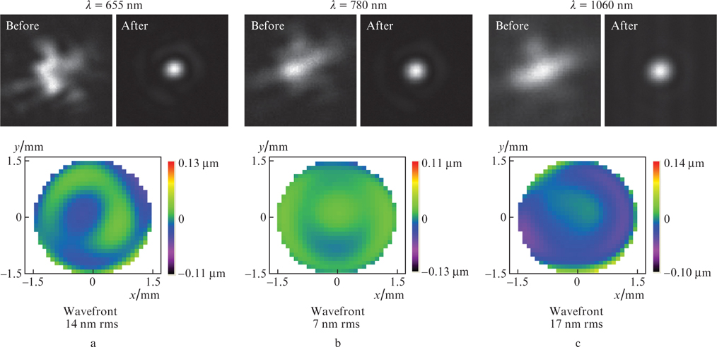
Figure 7. Tests of Pharao convergence at λ = (a) 655 nm, (b) 780 nm and (c) 1060 nm. In each case we show the best focused beam before and after (upper images) phase retrieval Pharao correction. Images in the bottom represent a residual wavefront with respect to the reference one (λ = 850 nm).
Download figure:
Standard imageThe full correction of the differential aberrations has been finally measured both in low- and high-power (100 TW) regimes of the UHI 100 laser at CEA Saclay. The UHI 100 laser is a 25-fs laser emitting pulses at 800 nm with a repetition rate of 10 Hz. Figure 8 shows three different measurements of the focal plane with this laser.
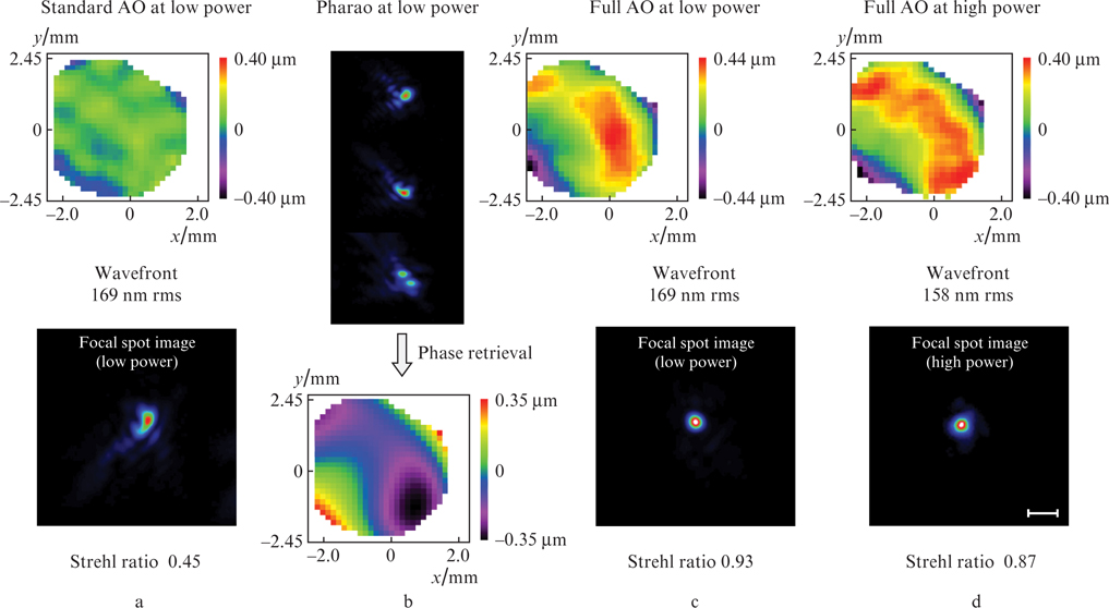
Figure 8. Full correction of a high-power UHI 100 laser at CEA Saclay (100 TW, 25 fs, 10 Hz). The upper images in (a, c, d) and the lower image in (b) represent the wavefront measurements. The lower images in (a, c, d) are the focal spot images on the CCD camera and the upper images in (b) are reconstructed images from the set of measured aberrations from the Pharao algorithm. The scale bar is 100 μm.
Download figure:
Standard imageThe same way as previously described, the deformable mirror can correct aberrations upstream from the wavefront sensor. Let us assume there are some wavefront distortions due to the final focusing optics (Strehl ratio 0.45), which degrade the focal spot image in Fig. 8a. Then Pharao measurement is applied (see Fig. 8b) and the correcting wavefront is retrieved. Once the differential aberrations are measured and the correction process is launched these aberrations are to be corrected. When applying this wavefront to a low-power regime, the Strehl ratio increases up to 0.93. Now the wavefront sensor does not detect a perfectly flat wavefront but it measures the wavefront that produces a perfect focalisation spot. The wavefront aberrations become 169 nm rms in a low-power regime. This wavefront has to be saved as a reference for every closed-loop iteration. Once increasing the laser power to a high-power regime one does not need the CCD camera anymore as the reference wavefront is saved. The resulting Strehl ratio in the high-power regime is 0.87 with the wavefront value of 158 nm rms measured by a wavefront sensor. The closed-loop process will continue measurements and corrections of the time dependent aberrations of the laser beam whereas the static differential aberrations will be pre-corrected and the best focal spot will be achieved. Moreover, the closed-loop frequency is then the same as the one achieved with the standard closed-loop. Thus, the Strehl ratio in the high-power regime is comparable with the one achieved in the low power regime. This proves the efficiency of this method to measure and correct high-power focusing systems in real time. This correction and control method could be successfully implemented for laser acceleration of high energy particles (electron and proton beams) and warm-dense matter physics.
3. Discussions and conclusion
The calibration of differential aberrations of an optical system is a long and delicate process [16]. That is why most of adaptive optics solutions propose only the measurement and correction of the wavefront before beam focusing without taking into account the differential aberrations. In this case the Strehl ratio will hardly exceed 0.60 at the focal spot position. In some cases, the focal distance of the final focal spot might be different at different experimental situations. Therefore, one needs to adjust the position of the pupil and to adapt the testing setup at the end-user installations. Moreover, the measurements of the wavefront at the laser focal plane will not allow correction in the high-power regime. Implementation of a simple focal spot camera and a phase retrieval algorithm allows achieving up to 0.93 of the Strehl ratio in the focal plane and thus an almost diffraction limited focal spot (Fig. 8). Currently, an increase in the laser repetition rate from 1 shot per minute to several Hz becomes more and more common feature in high-power lasers. The Pharao control and correction strategy opens a new pathway for high-power laser research from both fundamental and applicative points of view even for lasers running at several Hz. Highly demanded beam quality could be assured for extremely high laser intensity focused into a spot of several microns.
Acknowledgements
The authors acknowledge contribution from Dr. T. Ceccotti (CEA Saclay, France).