
Abstract
Suction cups are often found in nature as attachment strategy in water. Nevertheless, the application of the artificial counterpart is limited by the dimension of the actuators and their usability in wet conditions. A novel design for the development of a suction cup inspired by octopus suckers is presented. The main focus of this research was on the modelling and characterization of the actuation unit, and a first prototype of the suction cup was realized as a proof of concept. The actuation of the suction cup is based on dielectric elastomer actuators. The presented device works in a wet environment, has an integrated actuation system, and is soft. The dimensions of the artificial suction cups are comparable to proximal octopus suckers, and the attachment mechanism is similar to the biological counterpart. The design approach proposed for the actuator allows the definition of the parameters for its development and for obtaining a desired pressure in water. The fabricated actuator is able to produce up to 6 kPa of pressure in water, reaching the maximum pressure in less than 300 ms.
Export citation and abstract BibTeX RIS
1. Introduction
In robotics, attachment is a common problem in the cases in which the mobility of the robot must be provided in a complex or unstructured environment, as, for example, in water, where stability has a key role. In the case of robotic manipulators, adhesion can improve the handling capabilities of fragile or slippery objects. Reliability and reversibility are the two main aspects on which research has been focused to obtain effective attachment. Currently, different strategies have been implemented into robotic design to form an attachment, and these strategies can be classified by the technology used: magnets, grippers, guide rails, biomimetic devices, and suction cups [1]. The choice of an attachment strategy depends on several factors, including: the environmental conditions, type of substrate, and tasks required. Magnetic attachment, for instance, is applicable only on ferromagnetic substrates; gripping is suitable in the presence of beams or pipes and requires a robust control of the grasping force. Rail guided robots only work well on structures that are built ad hoc. Biomimetic devices are based on different technologies, such as dry adhesion by van der Waals forces [2], which work on smooth, clean surfaces, or micro-hooks [3], which are useful to attach on substrates with asperities. Suction cups exploit the reduction of pressure to generate attachment forces and can be used on both smooth and partially rough surfaces. Suction cups are the most widely used devices in climbing robots [1], but their application is limited by a possible failure in the presence of cracks or gaps in the substrate. Additionally, the design requires a pump to generate suction. The first problem may be overcome by using a set of suction cups [4, 5] that provide more stability to the robot. The second problem has been addressed using passive suction cups [6]. The latter solution results in a lighter and more energy efficient robot, but it reduces the attachment force and reliability of the system (compared to using active suction cups). Some commercial climbing robots [7] that utilize passive suction cups may be used in structured environments for applications such as cleaning the windows of tall buildings, pipe inspections, and surveillance. On the contrary, there are few examples in the literature of attachment systems that are able to work in an unstructured environment and even fewer that are able to work inside water. To be efficient in a wet environment, an attachment system should be extremely reliable and flexible. This requires the system to be redundant in terms of the attachment units to compensate for the possible failure of a single unit and requires the system to be able to control each suction unit independently. Furthermore, for usage in water, there are strong limitations in the available exploitable technologies. In the present manuscript, we describe the design of a novel bioinspired suction cup made of soft materials, with an integrated actuation that is able to work in water.
The paper is organized as follows: in section 2, we describe the analytical model and fabrication of the soft actuation unit and the entire suction cup. In section 3, we present the validation of the model and the characterization of the performance of the actuation unit and the proof of concept of the suction cup prototype. Finally, in section 4, we discuss the use of the model for the design of the actuator, and we analyse the advantages of the proposed design compared with state-of-the-art solutions.
1.1. Suction cups in biorobotics
Suction cups are frequently found as natural attachment solutions in numerous aquatic animals, such as limpet, echeneid fish, octopus, and so on. These animals offer a good source of inspiration for the development of efficient attachment systems because they can produce large attaching forces compared to their body weight [8]. Octopuses, in particular, have a peculiar sucker system that allows them to grasp objects of different sizes and to attach themselves to irregular surfaces. Furthermore, octopuses are able to finely manipulate small objects because of the peculiar configuration of the sucker muscles and the distribution of suckers along the arm [9]. For all of these reasons, the octopus sucker inspired the design of artificial suction cups. Few examples of bioinspired artificial suction cups can be found in the literature. Bing-shan et al [10] developed a shape memory alloy actuated suction cup that was able to work in air with the actuator embedded inside the device; Bandyopadhyay et al [8] developed suction cups for use in water, actuated by pumps. Grasso et al developed a dynamic simulator to model the functioning of the octopus sucker and to provide the tools for the design of bioinspired artificial suction cups [11]. Other authors improved the efficiency and the performance of suction cups by exploiting traditional actuation technologies, implementing innovative control strategies [12] and improving the design [13].
The aim of this paper is to introduce a novel concept for a suction cup inspired by an octopus sucker and to describe the design process, fabrication method, and performance of the actuation unit. Our unique solution has an embedded soft actuation mechanism that is able to work in water and can be miniaturized to a millimetre scale [14].
1.2. Bioinspiration
In recent years, octopus suckers have been studied because of their capacity to generate strong attachment forces on all non-porous surfaces. The morphology of the Octopus vulgaris sucker has been carefully described, and a hypothesis of the attachment mechanism has been suggested [15]. An octopus sucker is a muscular-hydrostat [16, 17] that consists of two parts: a hollow inner portion, the acetabulum ((A) in figure 1), and an outer disk-like portion, the infundibulum ((I) in figure 1). These two portions are connected by an orifice ((o) in figure 1). The sucker structure is arranged in a three dimensional array of muscles composed of radial, circular, and meridional fibres (figure 1). The radial muscular fibres cross the entire thickness of the sucker structure, the circular fibres are oriented parallel to the orifice aperture, and the meridional fibres extend down from the suckerʼs apex to the infundibular portion. The octopus performs an attachment by coming into contact with the substrate, forming a seal to prevent water leakage, and reducing the internal pressure via the contraction of acetabular radial muscles. The attachment capacity of an octopus is due to the exceptional capability of infundibular tissues to be perfectly compliant to the surface profile of the objects [18] to which the sucker comes in contact. Moreover, an octopus exploits the high bulk modulus of water to generate a negative pressure inside the sucker [19] and thus can maximize the difference of pressure compared to the environment.
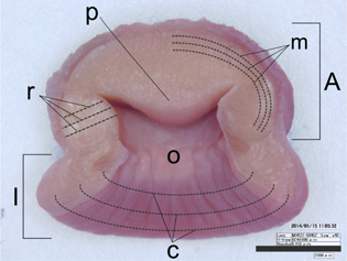
Figure 1. Photograph of an O. vulgaris sucker. Pictured: the acetabulum, (A) infundibulum, (I) orifice, (o) protuberance, (p) circular muscles, (c) radial muscles, (r) and meridional muscles, (m). The scale bar is equal to 2 mm.
Download figure:
Standard image High-resolution image2. Materials and methods
2.1. Actuation unit
2.1.1. Design
In the present work, we focused on mimicking the acetabular radial muscles that are responsible for the production of suction in the octopus sucker (section 1.2). The development of an artificial bioinspired device that mimics a biological system requires the use of a compact actuation method. An actuation unit must be embedded in each suction cup and must be activated independently from all other suction units. Dielectric elastomer (DE) actuators were identified as proper actuators to replicate the function of the acetabular radial muscles. Compared to traditional actuation technologies (e.g., electrical, piezoelectric motors, etc), DE actuators do not require a transmission, are lighter and are more compact. Among the soft actuators, DE actuators have the best trade-off between the actuation strain rate and force generated [20]. DE actuators meet the specifications of being soft and generating high pressures that can be exploited for attachment of the artificial prototypes combined with a low electrical power consumption [14]. The DE actuator consists of two compliant electrodes separated by a dielectric medium. DE actuators exploit the electric field applied between the electrodes to generate mechanical work. The opposite charges on the two electrodes are attracted to each other, thus producing a compressive stress on the compliant dielectric layer that is consequently deformed. The principle at the base of the DE actuators, in a planar configuration, is described by the following equation [21]:

which relates the voltage V applied to the two electrodes and the electrostatic pressure P generated on the dielectric in the direction of the electric field. The parameter t is the thickness of the dielectric membrane interposed between the two electrodes, ε is the relative dielectric constant of the material, and ε0 is the dielectric constant of vacuum. The actuation unit was designed as shown in figure 2. The DE actuator (active membrane, am, in figure 2) is hydrostatically coupled with a passive membrane (pm in figure 2) via a chamber filled with fluid ((f) in figure 2). Water was chosen as the first solution, as it was effective as a proof of concept. The two membranes (active and passive membranes) are sealed by two rigid circular frames (rf in figure 2). The application of a voltage to the DE actuator results in a thickness variation and an area expansion of the active membrane. This configuration induces a pressure change in the fluid inside the chamber defined by the two membranes, as it has already been demonstrated for an actuator with a single layer [22]. In the present work, this concept is adopted and designed to maximize the pressure difference inside the chamber during actuation.

Figure 2. The design of the actuation unit (section view) in (a) rest state and (b) activated state. am, active membrane (DE actuator); pm, passive membrane; f, fluid; and rf, rigid frame. The pressure inside the actuation unit decreases when high voltage is applied.
Download figure:
Standard image High-resolution image2.1.2. Model of the actuation unit
The membrane can be modelled as a thin diaphragm, inflated with an internal pressure given by the injected fluid. The internal pressure is equilibrated by the stress given by the traction of the membrane during expansion [23]. A relation between pressure and internal volume can be found, equilibrating the force given by the internal pressure times the area of the membrane and the force generated by the membrane at the rim of connection with the rigid frame (figure 3). The force F
 acting on the membrane is calculated as the pressure difference times the area of the diaphragm. The reaction force to the stretch of the membrane FF at the frame is calculated as the total membrane stress
  times the cross-sectional area of the membrane at the perimeter of the frame. The equilibrium is calculated in the vertical axis (figure 3):

where F
 is the force at the frame of the pressure, R is the radius of the membrane in rest state, F
 is the force of the membrane in vertical direction and t is the thickness of the membrane. The stress of the membrane
  has two components: an initial stress σ0 due to prestretch of the membrane and a component
  generated by the stretch of the membrane during inflation. The latter depends, according to Hookeʼs law, on the strains in radial and tangential direction and on the Young modulus of the material (Ym) [23]. The radial strain is considered constant over the entire membrane, because the bending moments are neglected, an assumption that is valid for the thin membrane that we are considering. The radial strain is calculated from the length of the parabola that describes the deflection curve of the inflated membrane respect to the base length with no pressure applied:

where w0 is the height of the centre of the diaphragm. Assuming that the tangential strain is equal to radial strain through the entire membrane [23], the total stress resulting from the deflection of the membrane is:

where νm is the Poissonʼs ratio. The angle α in figure 3 is derived from the slope of the diaphragm at the rim, which is the derivative of the parabolic curve that describes the deflection of the membrane, calculated at the rim:

Combining (5) with (2) it is possible to obtain a relation between the pressure and the central height of the diaphragm:

The thickness t of the diaphragm decreases as the surface of the membrane increases for the effect of the inflation. Considering that the material is incompressible, the following relation for the thickness as function of the height of the parabola was found, equating the volume of the membrane in rest state and its volume during expansion, calculated as the surface of the paraboloid times the thickness of the diaphragm:

where t0 is the initial thickness of the membrane. Equation (7) can be then integrated in (6). In order to find a direct relation between the volume of the fluid contained by the membrane and the pressure generated, the volume of the paraboloid is inserted in (6) and (7), replacing the height of the paraboloid w0 with:

where Vol is the volume enclosed by the paraboloid with base radius R and height w0. The effect of the actuation was then considered and included in the equilibrium equation to have an exhaustive description of the electro-mechanical interaction. The application of high voltage between the electrodes produces an electrostatic stress that acts in opposite direction respect to the stress  . The electrostatic stress is defined by Maxwellʼs stress tensor [24]:

where E is the electric field and δij the Kronecker delta. The electric field was considered uniform over the entire membrane, as in the case of a capacitor with parallel plates positioned at a distance t. With this simplification, the electrostatic stress in radial direction, perpendicular to the electric field can be expressed by (1) and inserted in (4) as a third term of the total stress  , that takes the final form:

This linearized model considers a linear elastic material, that is an acceptable approximation only for a limited range of the stress–strain curve of the acrylic tape that was used in the experiments [25], but is sufficient to qualitatively evaluate the effect of the geometric parameters on the actuation performance.
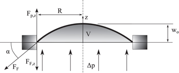
Figure 3. Schematic representation of the forces acting on the diaphragm during expansion under uniform pressure. R, radius of the membrane in rest position; w0, height of the paraboloid described by the inflated diaphragm; △p, difference of external and internal pressure; V, volume of fluid enclosed by the diaphragm; F , force acting on the membrane due to internal pressure; FF, force acting on the rim due to the stretch of the membrane.
Download figure:
Standard image High-resolution image2.1.3. Fabrication of the actuation unit
The DE actuator was designed with a widely available acrylic material (VHB 4905, 3 M), with electrodes made of silver conductive grease (Circuit Works CW7100, Chemtronics). The acrylic tape was uniformly prestrained to 300%, resulting in a final thickness of approximately 50 μm. A simple device was built to uniformly stretch the membrane in a radial direction, following the design of a folding mechanism [26]. Actuators with several layers were obtained to construct a sandwich structure of single-layer actuators, exploiting the adhesiveness of the tape to bond one layer to another. A specific procedure was used to avoid the formation of air bubbles in between the layers. The two membranes, which must be bonded, were first attached to two circular frames with different diameters. At this stage, the two frames aligned concentrically were placed inside a vacuum bag and the bag was sealed. Air was removed, and the collapsing bag pushed the membranes together, so that the air was not trapped between the two adjacent layers. This method dramatically reduced the formation of air bubbles, aiding in the reproducibility of the design (as described in section 3).
Six actuation units with a varying number of layers, from one to six, were developed and fabricated. The passive membrane was made with the same procedure as the active membrane but without the electrodes. Therefore, the active and passive membranes had comparable mechanical characteristics. When fluid was injected inside the actuation unit, the two membranes expanded outward symmetrically. The diameter of the actuator was set at 12 mm based on the specification of the biological sucker, as defined in a previous work [27].
2.1.4. Experimental setup of the actuation unit
The aim of the experiments was to measure the pressure difference that the actuation unit was able to generate. To test this capability, the actuation unit ((B) in figure 4) was bonded on a rigid cylindrical chamber ((A) in figure 4) and hydrostatically coupled with the passive membrane of (B). During the experiments, the pressure in the actuation unit (B) and in the rigid chamber (A) was recorded. The initial pressure inside the actuation unit was dependent on the volume of the fluid enclosed and the number of layers that composed the actuator. The experimental setup consisted of two main parts (figure 4) : (1) the actuation unit (B) sealed on a chamber filled with a fluid (A) and (2) a hydraulic piston (C) that was used to inject the fluid in the actuation unit coupled with a microslide stage (D). The microslide stage was equipped with a laser displacement sensor (E) that was used to calculate the fluid volume injected in (B). There were two differential pressure sensors (26pc series, Honeywell) (F): one connected to the actuation unit (B) and the other connected to the lower chamber (A). A board equipped with a high voltage dc/dc converter (EMCO corporation) that was able to generate up to 5 kV was used to supply the high voltage for the actuation unit. The data acquisition board, the high voltage dc/dc board, and the laser were connected to a PC to record the data synchronously. The procedure for the experiments included four steps:
- (i)Chamber (A) was filled with water and the actuation unit was sealed on this chamber. Syringe (G) was used to remove the air remaining inside chamber (A).
- (ii)The actuation unit (B) was filled with liquid injected by hydraulic piston (C) connected to the microslide stage (D). The volume was calculated from the displacement measured by laser (E). The piston was used to set the initial volume inside the actuation unit and was maintained fixed during actuation.
- (iii)The pressure inside chamber (A) was adjusted, removing or injecting fluid with syringe (G). The pressure before activating the actuator was regulated to be equal to the atmospheric pressure, simulating the condition in which the actuation unit was surrounded by fluid at the same pressure.
- (iv)A high voltage was applied to the actuator, beginning at 1 kV and increasing in steps of 250 V, up to 2.5 kV.
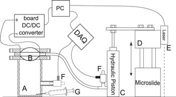
Figure 4. Experimental setup: rigid cylindrical chamber, (A) actuation unit, (B) hydraulic piston, (C) microslide stage, (D) connected to the piston; laser displacement sensor, (E) differential pressure sensor, (F) syringe for pressure regulation (G).
Download figure:
Standard image High-resolution imageSteps (ii)–(iv) were repeated, injecting five different amounts of liquid, and the pressure was measured by pressure sensors and was recorded. The pressure difference was calculated as the maximum difference between the average value of the pressure, measured in a time window of one second, before actuation and the minimum value recorded during actuation. The pressure difference has a positive sign, as the pressure during actuation is always lower than the pressure in non-actuated condition.
2.2. Suction cup
2.2.1. Design
In figure 5, an overview of the complete artificial device is provided. The artificial suction cup consists of an actuation unit ((a) in figure 5) bonded to a passive component. The actuation unit (described in section 2.1.1) mimics the acetabular radial muscles of the octopus sucker, generating the pressure difference respect to the external environment; the passive component mimics the infundibulum of the octopus sucker, allowing the device to be sealed on the substrate during attachment (this passive component is called the artificial infundibulum throughout the rest of the present work).
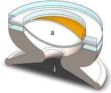
Figure 5. Concept of the bioinspired suction cup with the actuation unit embedded in the acetabulum (a) connected to the passive artificial infundibulum made of silicone (i).
Download figure:
Standard image High-resolution imageThe passive component is made using a soft material and is bonded directly to the rigid frames of the actuation unit. The liquid enclosed in the passive component, when it is sealed on the substrate, defines a second chamber that is hydrostatically coupled with the active unit. The actuation unit can be used to generate a change in the pressure in both chambers ((a) and (i) in figure 5) due to the hydrostatic coupling.
In the octopus sucker, when acetabular radial muscles are contracting, the internal volume of the sucker tends to increase. Because of the incompressibility of water, the internal volume does not change (the muscular contraction is in fact isometric), but a pressure drop is generated instead. In order to have attachment, the sucker must be sealed on the substrate before contraction of the radial muscles, and the contraction is associated with a small variation of volume due only to the amount of water enclosed in the sealed infundibulum, flowing into the acetabulum through the grooves. As the acetabular muscular hydrostat, the actuation unit is incompressible. When the active membrane is actuated, its thickness decreases and the volume enclosed by the membranes tends to increase. In case the sucker is not attached to a substrate, the effect is an increase of the volume of the infundibular chamber ((i) in figure 5). In case the suction cup is attached to the substrate, the water inside the infundibulum resists the volume expansion, and thus the pressure of the water inside the suction cup decreases, generating attachment force. The attachment process proposed using the DE actuators can be summarized as illustrated in figure 6. First, the suction cup is pushed on the substrate (a) and a seal is formed (b). The pressure inside the infundibulum in this phases equals the external pressure Pext. Then, the activation of the actuation unit induces a reduction of the interior pressure, both in the active unit ((a) in figure 5) from P0 to Pa and in the chamber below it ((i) in figure 5) from Pext to Patt. (c). The reduction of pressure is the same in both chambers. The attachment force is determined by the difference between the pressure of the water inside the infundibular part and the environmental pressure multiplied by the area of the artificial infundibulum that is sealed by the rim on the substrate.

Figure 6. Proposed attachment mechanism with a hydrostatically coupled DE actuator (section views). (a) Suction cup approaches the substrate; (b) the seal is formed on the substrate; (c) the activation of the actuator produces a change (reduction) in the water pressure inside the actuation unit and inside the artificial infundibulum. The arrows represent the electrostatic pressure acting on the active membrane, that generates the pressure difference inside the actuation unit.
Download figure:
Standard image High-resolution image2.2.2. Fabrication of the active suction cup
A suction cup prototype was developed based on the design shown in figure 5 to provide a proof of concept of the design described in section 2.2.1. In particular, the prototype was exploited to verify the simplification made in tests on the actuation unit (where a rigid chamber was used). The artificial infundibulum must, in fact, match the hypothesis to perfectly seal on the substrate and to be rigid enough to sustain the difference of pressure without collapsing. Based on the gathered results on the actuation unit performance presented in section 3.2, a qualitative test was carried out to prove the feasibility of the actuator design proposed in this work. The artificial infundibulum was made of Dragon-Skin silicone (Smooth-On, shore hardness A10) (as shown in figure 7, left) using a mould that replicates the morphology of a real octopus sucker [27]. The artificial infundibulum was glued to the rigid frame that holds the membranes of the actuation unit (figure 7, right). The actuator was fabricated with the procedure described in section 2.1.3 and was composed of six layers. The size of the artificial infundibulum was defined in accordance with the geometrical proportions that have been observed in the octopus sucker. In fact, the natural ratio (10 : 1) between the action area of the radial muscles (responsible of the suction generation) and the orifice area (which is proportional to the diameter of the infundibulum) in an octopus sucker was maintained in the case of the artificial prototype.
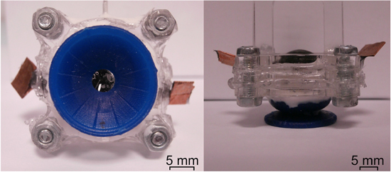
Figure 7. Suction cup prototype, consisting of the actuation unit, held by a plexiglass frame, and the artificial infundibulum, which is made of silicone. Bottom view (left) and side view (right). The connection for the high voltage supply is visible on the actuation unit.
Download figure:
Standard image High-resolution image2.2.3. Experimental setup of the suction cup
The prototype of the active suction cup, consisting of the actuation unit and the artificial infundibulum, was tested in water. A setup equipped with a pressure sensor was used to measure the pressure generated by the actuation unit inside the artificial infundibulum. A small plexiglass box with a hole in the bottom face connected to the pressure sensor (26pc series, Honeywell) was filled with water, and the suction cup was immersed in the water. Plexiglass was chosen as substrate for the preliminary test for its low surface roughness.
The silicone infundibulum was pressed on the bottom surface with the pressure sensor beneath it, and a constant force of 1 N was applied to maintain close contact with the substrate. The force is necessary to deform the silicone infundibulum and have a close contact between the infundibulum and the substrate.
The aim of the test was to prove the concept of the suction cup and to verify that a pressure difference could be generated in a non-ideal condition of a deformable infundibulum.
3. Results
3.1. Model validation
The model presented in section 2.1.2 was implemented using the geometrical parameters of the actuation unit shown in section 2.1.3. The Young modulus Ym and the initial stress σ0, which were the unknown parameters, were set to fit the experimental volume–pressure curve measured on the actuation unit with different number of layers. The experimental data of the volume–pressure curve were normalized respect to the number of layers and averaged, as shown in figure 8. The values that best fitted the experimental curve were σ0 = 83 kPa and Ym = 150 kPa. The value for Young modulus is comparable to the one calculated by the uniaxial tensile test of VHB acrylic film found in [28], that shows an almost linear trend of the stress–strain curve from 100% to 400% of stretch. The measure of the passive characteristic of the membrane is fundamental also to validate the repeatability of the mechanical features of multilayer actuators. The stiffness of the system is directly proportional to the thickness of the diaphragm and thus to the number of layers.
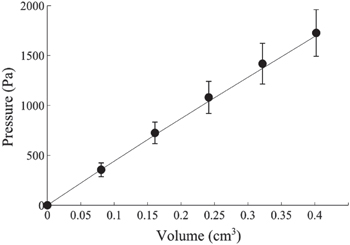
Figure 8. Experimental data (dots) of the non-actuated pressure–volume characteristic of the actuation unit, normalized for the number of layers, with error bars representing standard deviation, and the model (solid line) with parameters Ym and σ0 optimized to fit the experimental data.
Download figure:
Standard image High-resolution imageFigure 9 shows a direct comparison between the experimental data and the model. The model shows a good prediction of the passive behaviour of the membrane, in the range of volumes of the experiments. The second step was to validate the model in the case of application of a differential potential between the electrodes. Using the setup described in figure 4, the pressure was continuously monitored both in the lower chamber ((A) in figure 4) and inside the actuation unit ((B) in figure 4). All of the actuators were tested in a range of volumes and voltages where failure due to electrical breakdown, with a safety margin considered, did not occur. The voltage threshold used for the experiments (2.5 kV) was the maximum voltage at which the actuator did not fail when using the maximum volume of the injected fluid. A comparison between the measurement of the pressure difference generated by an actuator with one layer and the pressure difference expected by the model is show in figure 10. Each actuation unit was tested with five different initial conditions determined by the internal volumes (between 0.08 cm3 and 0.4 cm3), and for each condition the actuation was performed with seven different voltages (between 1 kV and 2.5 kV). The pressure difference was measured and recorded during actuation. The pressure difference generated by the actuation is an indicator of the performance of the actuation unit because it represents the pressure that can be exploited for the attachment of the suction cup. The result of the experiments is shown in figure 11(a). A comparison with the model shows a good match with the experiments for the actuation unit with a number of layers up to four (figure 11(b)). For the case of a single layer actuator the error in predicting the maximum pressure difference is less then 10%, while for the case of four layers the error increases to more than 20%.
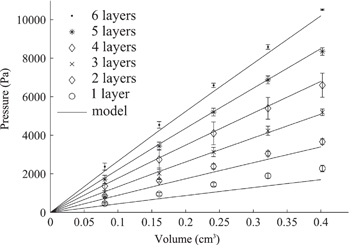
Figure 9. Pressure–volume characteristic of the actuation units with different number of layers with no voltage applied to the actuator, including error bars representing standard deviation, compared to the model (solid lines).
Download figure:
Standard image High-resolution image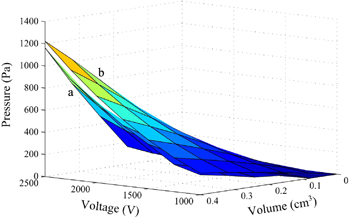
Figure 10. Direct comparison of the experimental data (a) with the model (b) of the pressure difference generated inside the actuation unit made of an actuator with one layer, for different internal fluid volumes and for different voltages applied.
Download figure:
Standard image High-resolution image
Figure 11. Pressure difference inside the actuation unit plotted against the internal fluid volume and actuation voltage. Each surface represents an actuator with an increasing number of layers, from 1 to 6; (a) experimental data; (b) analytical model.
Download figure:
Standard image High-resolution image3.2. Perfomance of the actuation unit
After testing under safe conditions, the actuators were tested until electrical breakdown occurred, applying a fixed voltage of 2.5 kV and increasing the amount of liquid with fixed steps of 80 mm3. The results are shown in figure 12 and indicate a maximum generated pressure difference of almost 7 kPa. The dynamics of the change in pressure inside the actuation unit was also evaluated to estimate the speed of attachment. The pressure drop inside the actuation unit was almost instantaneous because the membranes and the liquid do not move during activation, as the liquid inside the chambers is incompressible. The measurements indicate that 80% of the change in the pressure occurs in approximately 100 ms, and 90% of the change in pressure occurs in less than 300 ms (figure 13).
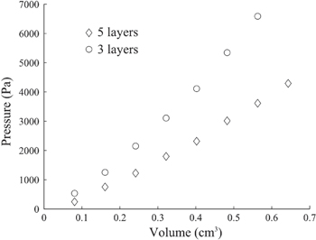
Figure 12. Pressure difference measured inside the actuation unit plotted against the internal volume. Actuators with three and five layers were tested, increasing the volume of fluid inside the actuation unit until breakdown occurred. The voltage applied was 2.5 kV in all the tests.
Download figure:
Standard image High-resolution image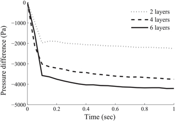
Figure 13. Recording of the pressure difference inside the actuation unit during activation at 2 kV, for actuators with two, four and six layers. Pressure is indicated with negative sign as the initial pressure was normalized to zero in order to have a direct comparison between different actuators.
Download figure:
Standard image High-resolution image3.3. Suction cup testing
The prototype of the suction cup was tested with the setup described in section 2.2.3. The experiments were intended to confirm the possibility of generating pressure inside the deformable artificial infundibulum. The experiments were designed to verify that the pressure difference could be maintained in time, without decreasing. High voltage was applied and maintained for 4 s, and the pressure inside the infundibulum and the increase of voltage were recorded for each test. A maximum pressure difference of 6 kPa without a decrease in that time window was recorded, confirming the feasibility of generating a pressure difference that can be used for the application of attachment in water. This result can be considered as the proof of concept of the suction cup design and the actuation with DE actuators. The result is shown in figure 14.
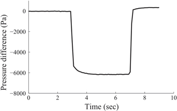
Figure 14. Recording of the pressure inside the artificial infundibulum of the suction cup prototype. The actuator was activated for 4 s while the artificial infundibulum was sealed on a plexiglass substrate.
Download figure:
Standard image High-resolution image4. Discussion
The present work highlights the usability of DE as actuators suitable for generating suction under wet conditions. A model was used to validate the fabrication process and the performance of the actuator. The model considers the material of the actuator linear and elastic and neglects the contribution of the carbon grease electrodes and the influence of the actual coverage of the electrodes on the membrane. The electrostatic pressure is considered to be generated by two parallel electrodes, simplifying the actual paraboloid shape. Despite these simplifications, it gives useful indication on the expected performance of the actuation unit. The model can be used to evaluate the number of layers needed to obtain a target pressure and to validate the fabrication method. Since the generated pressure difference is directly proportional to the total thickness of the actuator made of multiple layers, the number of layers can be easily calculated with the model. Figure 15 shows the experimental data collected on all the actuators normalized for the number of layers. The average value of pressure recorded in the tests with the same number of layers was calculated before normalization. The differential pressure is inferior to the one expected from the model, indicating that stacking multiple layers produces a decrease of the performance that must be taken into account while designing the actuation unit. The model can also be used to investigate the scalability of the actuator and the possibility to miniaturize the suction cup. A comparison of the performance for different radii of the actuator was done scaling down the maximum injectable volume to a quantity that induces the same reduction of the thickness of the membrane, so that the same maximum voltage (and thus electric field) can be applied in all the cases. Figure 16 shows the comparison for actuators with different radii, indicating an inverse proportionality between radius and pressure generated. The pressure indicated is the maximum that can be generated with the maximum safe voltage (2.5 kV) at the maximum injectable volume. The force generated by the suction cup is thus directly proportional to the radius of the actuator, being the product of the pressure times the area of the actuator. Hence, the force of the suction cup scales proportionally with the diameter.
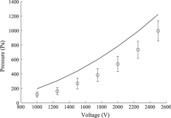
Figure 15. Pressure difference inside the actuation unit of all the actuators tested, with internal volume of 0.4 cm3 (circles). All data are normalized to the number of layers and averaged, with error bars representing standard deviation. Experimental data are compared to the model (solid line).
Download figure:
Standard image High-resolution image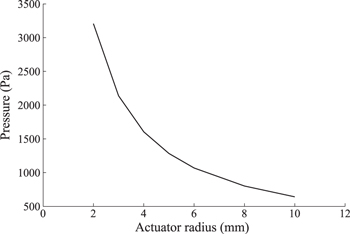
Figure 16. Maximum pressure difference that can be generated by a single layer actuator for different radii.
Download figure:
Standard image High-resolution image
The results presented in this paper show the feasibility of a bioinspired suction cup with DE actuators that works in water. The fabrication process was developed to obtain actuators with a desired number of layers, without encountering, to date, any limitations on the number of layers that can be stacked. The performance can be largely improved considering that the force generated depends on the geometry of the artificial infundibulum. In the suction cup prototype, the surface morphology of the artificial infundibulum is a simplification of the octopus infundibulum, and the material chosen is a trade-off between ease of fabrication and the similarity with the biological tissue. Because the attachment force is a combination of the actuator performance and the characteristics of the artificial infundibulum, it will be considered a parameter for the optimization of the infundibular portion of the suction cup. The material and surface geometry of the infundibulum will be further investigated to improve the attachment on substrates with different roughness, which is essential for real-world applications. The efficiency of the attachment when scaling the dimensions needs to be investigated as well. Compared to existing devices, the suction cup presented in this paper has the advantage of having an integrated actuation mechanism. Therefore, it is independent from an external actuation unit, unlike pump-based suction cups. Compared to suction cups actuated by motors or fans, the proposed suction cup has the advantage of having a reduced dimension and of not having gears or insulation issues in the actuator design. Moreover, the actuator used is soft and lightweight (less than 3 g for the actuation unit), with a low power consumption (less than 100 mW). The particular configuration of the suction cup, made of two distinct parts (the actuation unit and artificial infundibulum), makes this device more adaptable to the desired application. Indeed, the pressure generated and the type of substrate to which the infundibulum must attach can be designed separately. The actuator can be scaled to reduce the overall dimensions, with the only limitation consisting of the manual procedure of stacking the dielectric layers. The rigid parts of the suction cups are limited to the frames that hold the membranes, making this system suitable for application on soft robots and, in particular, on soft manipulators working in wet conditions [29]. Because of the potentiality of the proposed solution, other applications are possible, for example in surgical robotics. In fact, in minimally invasive endoluminal surgery, the main challenges are the stability of flexible tools and the harmless anchoring of surgical tools.