
Abstract
A prototype of borehole radar has been successfully tested in three sites for different purposes under a field condition. The objective of the prototype is providing an effective down-hole tool for detecting targets in deep boreholes situated in a relatively high conductivity area such as the metal ores. The first testing site is at a geothermal field. The fractures extending more than 20 m from the borehole are delineated by the borehole radar in the single-hole reflection mode. The second testing site is located in a jade mine for basement evaluation. The cross-hole measurement mode was used to detect the cavities made by previous unorganized mining activities. Several high-velocity anomalies were found in the velocity profile and presumably the targets of the mine shafts and tunnels. The third test site is located in a mineralized belt characterized by low resistivity less than 1000 Ohm m, the surface-borehole measurement was carried out and the data were processed with velocity tomography. The low-velocity zone corresponds to a mineralized zone from geological records. The three testing results proved the readiness of this borehole radar prototype for further deployment in more complicated and realistic field situations.
Export citation and abstract BibTeX RIS
1. Introduction
Ground penetrating radar (GPR) has been widely applied for detection and evaluation of subsurface geological targets (Daniels 2004, Slob et al 2010). However, strong electromagnetic absorption from lossy geologic media limits its detection depth. For most situations, the detection depth is within tens of metres in normal geological media. Borehole radar is one effective way to overcome this limitation. The detection depth for borehole can be vertical and radial. The vertical detection depth is the borehole depth, while the radial detecting range depends on the antenna frequency and the resistivity of the surrounding earth. The earth's resistivity depends greatly on the water content. The radial detection depth for the borehole radar can be as far as tens of metres and often surpass the detection depth by surface GPR, because the coupling between the antenna and the formation for the borehole case is better than the surface GPR case. The coupling between antenna and the surrounding medium depends on the matching between the antenna radiation resistor and the characteristic impedance of the medium. In other words, as the two values are closer, the coupling is better. As the antenna is located in the borehole or other material, the fact that the characteristic impedance becomes closer to radiation resistor results in better coupling.
The borehole radar has several advantages due to its working setting. First, the borehole radar can sense a larger region than the surface GPR. Second, it is less affected by surface electromagnetic interference, and closer to the targets of interest. Last, it is especially effective for detecting water-bearing fractures and cavities (Liu 2006, Liu and He 2007) due to large dielectric contrast between water and rocks. Of course, borehole radar has its disadvantages such as the necessity of a borehole and the difficulty to define the azimuth of target using an omni-directional antenna for the single-hole reflection mode. The borehole radar generally has three measuring modes, single-hole reflection, cross-hole tomography and surface-borehole measurement.
The initiation of borehole radar development can be traced back at least to the 1970s. The early purpose was to find the fractures in crystallized rocks to evaluate the possibility of storing nuclear waste. Nickel et al (1983) tested the single-hole reflection by an impulse borehole radar in the salt dome, and the cross-hole measurement with a continuous-wave system. Wright et al (1984) developed the single-hole reflection radar and used it in a project of radioactive nuclear waste disposal.
The international Stripa project in the 1980s aimed to develop and produce some techniques that can characterize the water flow in rocks related to nuclear waste disposal (Olsson et al 1992). Most nuclear waste was stored in a place hundreds of metres below the surface. The mobility mechanism of this nuclear waste is closely related to water flow in fractures. Therefore, the determination of the fracture distribution and its permeability is crucial for nuclear waste disposal. The RAMAC borehole radar is developed for this kind of study.
During the 1990s, scientists and engineers in Tohoku University developed the full-polarimetric borehole radar (Miwa et al 1999, Sato and Miwa 2000). Furthermore, to overcome the azimuth ambiguity of a single-hole reflection, they also developed the directional borehole radar, which utilized optical sensors to simplify the down-hole equipment and achieved excellent results (Sato and Takayama 2007, Takayama and Sato 2007).
Scholars in South Africa used borehole radar to delineate gold ores and solved some mine engineering problems (Vogt and Pisani 2004). The Ventersdrop contact reef (VCR) is a gold layer located in the Witwaterand basin. A borehole radar was used to image VCR 80 m away from the borehole.
To reduce the cost and increase the production, Fullagar et al (2000) tried to delineate McConnell massive sulfide nickel-copper ores in Canada by a borehole radar and a RIM system.
Siever and Elsen (2010) developed a directional borehole radar through more than 10 years of work on salt dome exploration. This system is a huge one, as long as 22 m and capable of operating in a borehole as deep as 2000 m, and can sense the reflection 300 m away from the borehole into the salt. It uses a standard logging cable for data transfer and control. The receiving antenna has a directional sensing device and can discriminate the wave from different directions.
Our objective is to develop a multi-functional, flexible borehole radar system that can operate in deep boreholes situated in a relatively high conductivity area such as metal ores with high-resolution measurement, and radial detecting range as far as possible. This system does not need a self-developed complex electronic circuit, and it is only an assembly of off-the-shelf components. Based on this philosophy, we developed a networker-based borehole radar system. The RF signal is converted and transmitted by optical fibres. The system can be operated in either the single-hole reflection mode or the cross-hole transmission mode. It is simple and easy to realize. After three field tests for different geological targets including fractures, ore boundary and jade mine cavity evaluation, the system is proven to be robust with great functionality.
2. Hardware buildup
Following the Tohoku University system, we developed a prototype of borehole radar as illustrated in figure 1. The major parts on the surface include network analyser, optic to electric (O/E) converter and electric to optic (E/O) converter. The downhole parts include miniaturized O/E and E/O converters, the transmitting and receiving antennas which are all omni-directional. The O/E and E/O converters are located inside the cylindrical antennas to prevent any electromagnetic interference. Antennas are enclosed in a specifically designed fibre glass tube with waterproof capability for more than 500 m in depth. The effectiveness is proven by the factory and field tests.

Figure 1. Diagram of our self-developed borehole radar prototype, (a) single-hole reflection and (b) cross-hole measurement.
Download figure:
Standard imageThe surface parts and the down-hole parts are connected together by the optic cable. For using the single-hole reflection mode, the transmitting and the receiving antennas are connected together, and then the down-hole probe assembly is connected to the surface devices by a multi-core cable. As for using the cross-hole mode, the transmitting and receiving sondes are located in two separate boreholes; each sonde is connected to the surface part by an optical cable. Apparently, the cross-hole mode can be easily changed into the surface-borehole mode.
The vector network analyser (VNA) transmits RF signals and the signals turn into optical signals after the E/O converter. The optical signals reach the down-hole O/E converter after a long distance, nearly lossless transmission in the fibre. The down-hole O/E converter then turns the optical signals back to RF signals which are radiated into the surround formations by the transmitting antenna. This process is called down-link. The up-link process is just the opposite procedure. The receiving antenna first senses the surrounding electromagnetic signals, which include the direct signals from the transmitter, and the reflected (scattered) signals from the geological targets. We need different processing and interpretation methods for each of them. The sensed RF signals turn into optical signal through a down-hole E/O converter; these optical signals pass into the surface O/E converter after long distance transmission. The optical signals turn into RF signals and reach the VNA port. The up-link process is completed. All the measurement is controlled by a PC which is connected to the VNA by a LAN cable. Some components are introduced in detail below.
The main functional part of the system is the VNA, which transmits and receives the RF signals and we need not make a complex circuit. This scheme is fitted for testing and development. We use a step-frequency measurement mode, and the scan bandwidth can be manually selected. We use an Agilent 5071B network analyser, and measured the signal range between 1 and 175 MHz. After considering our antenna set up we have chosen the total number of 1601 sampling points in carrying out the field projects.
As our borehole radar is based on the network analyser, the RF signal transmitting and receiving all occur on the surface. However, the important component transmitting and receiving antennas are all located in the down-hole sondes. Therefore, the electromagnetic attenuation between the surface and down-hole has been overcome by using the nearly lossless optic fibre.
We use a cylindrically symmetric dipole antenna which is fed at the middle point. The antennas are not resistively loaded. To probe deep into the formation, the antenna length is designed to be 1.5 m for a nominal central frequency of 30 MHz. The spectra for single-hole refection and cross-hole tomography are shown in figure 2; these spectra are all averaged values over certain intervals. It is noticed that the spectrum is very wide for single-hole reflection, namely from 20 to 110 MHz. The spectrum is basically flat, and only has a valley at 70 MHz. As for a cross-hole measurement, the spectrum is narrow, and has a central frequency of 20 MHz and another peak at 50 MHz. The signal to noise ratio become lower after 70 MHz. Comparing the spectra between single-hole reflection and the cross-hole measurement, we find that they are very different. We attribute this difference to the formation electromagnetic absorption. However, the borehole antenna is effective for measurement.
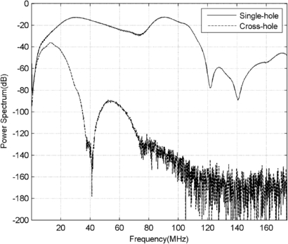
Figure 2. Measured averaged power spectra from single-hole reflection and cross-hole measurement in the fields.
Download figure:
Standard image3. Experimental results and analysis
3.1. Field test 1: Songjianghe geothermal file single-hole reflection
The testing site is located in the west flank of the Mt Changbaishan tourism zone, Jilin, China. Previous volcanic and magmatic activities of Mt Changbaishan resulted in abundant subsurface faults and fractures. These faults and fractures act as the reservoirs and movement channels of hot springs. The host rocks are mainly basalt and granite. Numerous geophysical investigations have been carried out to develop geothermal resources. The resistivity of these host rocks ranges from 102 to 105 Ohm m by surface geophysical prospecting. Boreholes were drilled at certain interesting locations which produced water. A borehole radar was deployed in one of the boreholes here to locate the fractures and study their lateral extension.
The testing borehole has a diameter of 30 cm and a depth of 350 m. A single-hole reflection was carried out in a depth interval: 53.5–165 m. Since the radar is a stepped-frequency one, the measured signals originally in the frequency domain were transformed into the time domain by the inverse Fourier transform. The original data were processed with very simple procedures including a band-pass filter and simple gain for easy and direct assessment of the data. We use a band-pass filter with plateau frequency from 20 to 70 MHz, and the plateau decreases gradually below 20 MHz and above 70 MHz, obeying a minus exponential function. Our gain function includes both linear and exponential parts:

where t is the time in ns, and α and β are two coefficients.
The time-domain radar profile is shown in figure 3(a). We find three 'scissors-like' events, which were manually picked up as shown in figure 3(b). Their depths are 55.8, 105.3 and 128.7 m, respectively. These three events are interpreted as fractures. After a simple migration process (Liu and Sato 2006), the fractures' true positions and distributions are shown in figure 3(c). The velocity is chosen to be 0.12 m ns−1 empirically by referencing the permittivity of the host rocks. The detected fractures corresponded to water intervals determined by well logging.

Figure 3. Fracture detection results in a geothermal field, located in the west flank of the Mt Changbaishan tourism zone, Jilin, China. (a) Single-hole reflection time profile, (b) manually picked up events and (c) interpreted fractures.
Download figure:
Standard image3.2. Field test 2: Xiuyan jade mine basement evaluation by cross-hole measurement
Produced in the Xiuyan county, Liaoning province, Xiuyan jade is one of the four most famous jades in China. The largest jade body was discovered on 18 May 1995, with a height of 25 m, and a diameter of 30 m. The volume is 24 000 m3 with the weight of 60 000 tons (figure 4(a)). It was broken from the mountain body on 12 July 2009 by natural fracturing. The slipping distance at the top of the broken jade was over 3 m. The local government intended to build a museum at the site; however, this plan is facing a major challenge due to the questionable foundation stability. The problem was caused by numerous unrecorded and unorganized mining activities in the vicinity of this massive jade body. In order to protect this geological site and improve the foundation stability, numerous boreholes were drilled and a concrete injection method was adapted to enforce the foundation. The borehole position map is shown in figure 4(b), where the words like 'J1' refer to the borehole name; the number following the borehole name is the borehole depth when the borehole was completed. Nevertheless, the injected concrete was found flowing into other holes, showing the existence of a complex subsurface fracture network in the vicinity of the giant jade body. The regional outcrop rocks are mainly marble, granite, etc with a resistivity of more than 1000 Ohm m; jade is characterized with a low resistivity of 600–1000 Ohm m. Targets are mined-out areas partially filled with concrete.
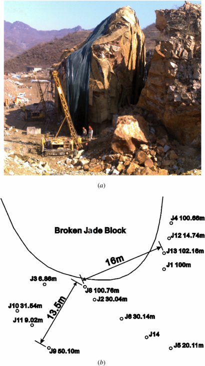
Figure 4. (a) Photo of a broken large jade block in a jade mine at Xiuyan, Liaoning Province, China, and (b) distribution map of the boreholes around the large jade block. The words like 'J1' refer to the borehole name, and the number following the borehole name is the borehole depth.
Download figure:
Standard imageTo evaluate the concrete injection effectiveness, cross-hole tomography was carried out between boreholes J8 and J13 (see figure 4(b)). The distance between these two holes is 16 m and both boreholes have a depth of 100 m originally. But both boreholes were shortened due to filling sediments at the bottom of the boreholes. The transmitter moves in borehole J8 from 28 to 66 m, and the receiver moves in borehole J13 from 18 to 80 m. The moving interval in depth for both the transmitter and the receiver is 1 m. Figure 5 shows the common source gather data, as the transmitter depth is fixed and the receiver moves in the receiving borehole for a certain depth range. The depth number is marked at the top of each figure.

Figure 5. The selected raw radar profiles for cross-borehole measurement between boreholes J8 and J13 as shown in figure 4(b). The data are the common source gather, as the transmitter depth is fixed and the receiver moves along the borehole in certain depth range. The depth number is marked at the top of each figure.
Download figure:
Standard imageThe ray path distribution is shown in figure 6(a). The data were processed by the velocity tomography software we developed ourselves. The velocity tomogram is shown in figure 6(b). The velocity is generally around 0.1–0.11 m ns−1, but there are five high-velocity anomaly zones marked as 'A', 'B', 'C', 'D' and 'E'. The velocities for the 'A' zone and the 'B' zone are extremely high (∼0.17 m ns−1); we inferred that they were air-filled cavities formed by some unrecorded mining activities. The velocities for 'C', 'D' and 'E' zones are moderately higher than the background. The velocities for 'C', 'D' and 'E' zones are 0.139 m ns−1, 0.130 m ns−1 and 0.126 m ns−1. There might be some mining tunnels filled with poorly consolidated concrete.

Figure 6. (a) The ray path distribution for the cross-hole measurement carried out between boreholes J8 and J13, and (b) velocity tomography image. The five high-velocity anomaly zones are marked by 'A–E'.
Download figure:
Standard imageThis case shows the capability of this borehole radar prototype in cavity and tunnel detection.
3.3. Field test 3: surface-borehole measurement at Baligou
This test site is located at the west part of Linjiang city, Jilin Province, China. The local rocks are mainly marble, schist, etc, which are important for the mineralization of gold and other metal ores. Marble and schist have relative low resistivity less than 1000 Ohm m. The targets are mineralized zones or ores for which the resistivity is generally low.
In order to explore the metal ores, quite a number of geological and geophysical investigations have been done in previous studies. Based on these works, a borehole was drilled with geological loggings to determine the existence and distribution of ores. We adapted the surface-borehole mode at this site after considering the terrain characteristics. This measuring mode is similar to the cross-hole mode as shown in figure 7, with a transmitter located in the borehole and the receiver located on the surface of the slope. Figure 7 is a sketch of the surface-borehole radar experiment performed at the top of a mountain. Tx and Rx mark the positions of the transmitter and the receiver, respectively. The position of the receiver relative to the borehole was measured to determine the transmitter–receiver distance.
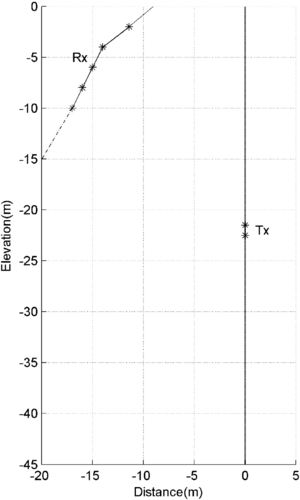
Figure 7. A sketch of field setting of the surface-borehole measurement at the top of a mountain (Baligou) for metal ore detection, the transmitter is located in a borehole, and the receiver is located on the slope's left side. The signs '*' mark the position of the transmitter or the receiver.
Download figure:
Standard imageConsidering the practical local situation, we used a common receiver mode here by using the fixed receiver on the surface and moving transmitter in the borehole. We have acquired five common receiver data sets as shown in figure 8. The number on the top of each figure is the depth of the receiver.

Figure 8. The raw radar profiles for surface-borehole measurement as shown in figure 7. A common receiver-measuring mode is adapted. The number at each figure is the receiver depth.
Download figure:
Standard imageThe 2D velocity tomogram is shown in figure 9. We find a dip low-velocity zone (as low as 0.091 m ns−1) between two marked lines, and this zone meets the borehole at 6–14 m. In general, previous studies (Wu et al 2011, Liu et al 2011) show that the low-velocity zone is caused by the large permittivity of the metal ores. The measured permittivity of the ores' samples by an open-ended probe technique (Wu et al 2011, Liu et al 2011) at this region is variable and has an averaged value of about 17, and the corresponding velocity is 0.071 m ns−1. We deduce that this zone is possibly related to a metal ore. This anomaly zone is consistent with the borehole geological logging showing mineralization at this borehole interval. There is also a high-velocity zone (as high as 0.146 m ns−1) above the low-velocity zone; the possible rocks are schist according to the regional geological records. The measured averaged permittivity of the schist samples is about 5, and the corresponding velocity is 0.134 m ns−1. The field value agrees with the measured one at the laboratory.

Figure 9. (a) The raypath distribution and (b) the inverted velocity distribution image from the surface-borehole testing.
Download figure:
Standard imageThis case primarily shows the applicability of our borehole radar for low-velocity discrimination and metal ore-related detection.
4. Conclusions
Three borehole radar test studies provide clear demonstrations of the success of the homemade borehole radar system and its capability of meeting different purposes. The resulting single-hole reflection profiles provide images of fractures in basalt up to more than 20 m from the borehole. The cross-hole velocity tomograms show ideal results even in low-resistivity host rocks. The velocity variation can be used to deduce geological anomalies such as cavities and different rock types.
Acknowledgments
The research was supported by the China national High-tech R&D Program 863 (grant no 2008AA06Z103) and the National Natural Science Foundation of China (grant nos 40874073 and 41074076).