
Abstract
A physical design study of the Circular Electron-Positron Collider (CEPC) booster is reported. The booster provides 120 GeV electron and positron beams for the CEPC collider with top-up injection. The booster is mounted above the collider in the same tunnel. To save cost, the energy of the linac injector for the booster is chosen as 6 GeV, corresponding to a magnetic field of 30.7 Gs. In this paper, the booster lattice is described and optimization of the cell length is discussed. A novel scheme of bypass near the detector of the collider is designed. The extremely low magnetic field caused by low injection energy is studied, and a new ideal of wiggling bands is proposed to mitigate the low-field problem. Beam transfer and injection from the linac to the booster are considered.
Export citation and abstract BibTeX RIS
1. Introduction
Soon after the discovery of the Higgs boson, the Circular Electron-Positron Collider (CEPC) was proposed. The Super Proton-Proton Collider (SPPC) could be installed later in the same tunnel as CEPC for pp, ep and ion collisions. In CEPC, the electron beam energy is 120 GeV, while in SPPC, the proton beam energy can reach 25–50 TeV for different choices of circumference and maximum bending field. There are two interaction points for e+e− collisions (IP1 and IP3), with the other two reserved for pp collisions (IP2 and IP4). Table 1 lists the main parameters of CEPC and SPPC [1].
Table 1. Main parameters of CEPC and SPPC.
| parameter | unit | CEPC | SPPC |
|---|---|---|---|
| energy | TeV | 0.12 | 35.6 |
| circumference | km | 54.4 | 54.4 |
| dipole field | T | 0.0657 | 20 |
| bending radius | km | 6.094 | 5.92 |
| beam current | mA | 16.6 | 1000 |
| bunch number | 50 | 5835 | |
| SR loss per turn | GeV | 3.11 | 0.0021 |
| SR power per beam | MW | 51.7 | 2.1 |
 |
mm | 1.2 | 750 |
| number of IP's | 2 | 2 | |
| luminosity | cm−1·s−1 | 2×1034 | 1.2×1035 |
As the injector of the CEPC collider, the booster should be able to provide full energy e+e− beams of 120 GeV for its top-up injection with maximum frequency of 0.1 Hz. To reduce synchrotron radiation (SR) loss at high energy, the bending radius of the booster should be as large as possible. It is decided that the booster will be mounted in the same tunnel as and above the collider, leaving space for the future SPPC. To save cost, the energy of the linac injector for the booster is chosen as 6 GeV, corresponding to a magnetic field of 30.7 Gs. The low magnetic field problems caused by low injection energy is one of central concern in the design, and a novel ideal of wiggling bands is proposed to mitigate the low-field problem in the booster.
2. Layout and main parameters
Figure 1 illustrates the layout of the booster above the CEPC collider. The booster shares the same tunnel as the collider with about the same circumference, while bypasses are arranged to keep the beam away from the detectors at IP1 and IP3. Electron and positron beams are injected from the linac to the booster through the transfer line LTB (Linac To Booster) in one of the 850 m long straight sections. The beam extraction at top energy takes place in other two straight sections. Electron and positron beams are injected to the collider through BTCe+ and BTCe− (Booster To Collider) transfer lines.

Fig. 1. Layout of CEPC and its booster.
Download figure:
Standard image High-resolution imageAs shown in Fig. 1, the collider is designed with four interaction points, where IP1 and IP2 are for e+e− collisionsof luminosity 2×1034 cm−2s−1 per IP, while other two IPs are reserved for SPPC. The circumference of the CEPC collider is 54.4 km, including 8 arcs of 5846.6 m, 4 arc straights of 850 m each and 4 interaction region straights of 1130 m each. The RF frequency of the booster is chosen as 1.3 GHz, a factor of two higher than that in the collider. There are eight RF stations in the booster, providing a total RF voltage of 5.12 GV. One RF station consists of 4 cryo-modules, each of which are 12 m long and contains eight 9-cell super-conducting cavities. Table 2 lists the main parameters of the CEPC booster.
Table 2. Main parameters of the CEPC booster.
| parameter | unit | value |
|---|---|---|
| injection energy | GeV | 6 |
| ejection energy | GeV | 120 |
| circumference | km | 54.4 |
| bending radius | km | 6.519 |
bending field  |
T |  |
| SR loss/turn | GeV | 2.814 |
| bunch number | 50 | |
| bunch population | 1010 | 2.0 |
| beam current | mA | 0.87 |
| RF frequency | GHz | 1.3 |
| total RF voltage | GV | 5.12 |
| SR power @120 GeV | MW | 2.46 |
| SR power density @120 GeV | W/m | 45 |
The bunch number in the booster is chosen to be 50, the same as in the collider. The bunch population is based on the assumption of 5% current decay in the collider between two top-ups. The synchrotron radiation power density of 45 W/m at 120 GeV in the CEPC booster is much lower than the 415 W/m of BEPCII [2].
For the very low synchrotron radiation damping rate, a scheme of single bunch injection from linac to booster is adopted. The electron and positron beams, with bunch population of 2×10¹⁰ and emittance of 0.3 mm·mrad, are injected into the central orbit of the booster. The overall transfer efficiency from the linac to the collider is assumed to be 90%.
The booster is capable of operating with a repetition frequency of 0.1 Hz. The typical magnetic cycle is given in Fig. 2. As shown in Fig. 2, the beam injection from the linac to the booster takes 1 second, the energy ramp takes 4 seconds, 1 second flat top is for beam extraction to the collider, and 4 seconds for magnets ramping down.
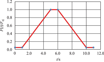
Fig. 2. Typical magnetic cycle in the booster.
Download figure:
Standard image High-resolution image3. Lattice
3.1. Choice of cell length
For the booster to be installed in the CEPC tunnel, its arc arrangement should be similar to the collider. However, the length of the cells can be optimized with the required beam properties and other parameters in order to improve cost performance. Lattice parameters scaling to the cell length are presented in Table 3.
Table 3. Lattice parameters scaling to the cell length.
| parameter | value | unit | ||
|---|---|---|---|---|
| Lcell | 47.2 | 71.7 | 94.4 | m |
| |kQlQ| ∝ L−1 | 0.044 | 0.029 | 0.022 | m−1 |
| βmax ∝ L | 81.2 | 123.3 | 162.3 | m |
| Dx ∝ L2 | 0.38 | 0.87 | 1.52 | m |
| νx,y ∝ L−1 | 189.2 | 124.6 | 94.6 | |
| αp ∝ L2 | 3.43 | 7.91 | 13.72 | 10−5 |
| ξ ∝ L−1 | 86.4 | 56.9 | 43.2 | |
| |kSFl| ∝ L−3 | 0.15 | 0.043 | 0.019 | m−2 |
| |kSDl| ∝ L−3 | 0.24 | 0.070 | 0.030 | m−2 |
| εx0 ∝ L3 | 6.8 | 23.8 | 54.40 | nm |
| νs ∝ L | 0.204 | 0.31 | 0.41 | |
| σxβ ∝ L2 | 0.74 | 1.71 | 2.97 | mm |
| σyβ ∝ L2 | 0.53 | 1.21 | 2.10 | mm |
| σxE ∝ L2 | 0.49 | 1.14 | 1.97 | mm |
| σx ∝ L2 | 0.89 | 2.06 | 3.57 | mm |
| σz ∝ L | 1.84 | 2.76 | 3.68 | mm |
It is indicated in Table 3 that the longer the cell, the larger the beta functions, dispersion, emittence and beam size, and also the smaller the chromaticity, the weaker the sextuples, and, more importantly, the fewer the number of cells and machine components. The cell length of the booster is then chosen as 71.7 m, about 1.5 times that of the collider of 47.2 m, as the baseline design. The total number of FODO cells in the booster is 764.
3.2. Lattice functions
The lattice of the booster is based on 60° FODO cells. The dispersion suppressor section (DIS) and its inversely arranged section (-DIS) are designed to make the booster dispersion free in the straight sections between the adjacent super-periods. The structures of the two types of super-period in the booster are shown below.

Download figure:
Standard image High-resolution imageThere are 8 arcs in the booster, each of which consists of 78 regular FODO cells and two dispersion suppressors (each containing one regular FODO cell and one straight FODO cell). There are two quadrupoles of 1 m each, 8 dipoles of 8 m each, and two sextupoles of 0.2 m each in a regular FODO cell of 71.7 m. The total length of an arc is about 5846.6 m. There are 12 straight FODO cells in the arc straight and 15 straight FODO cells in the IR straight (for IR2 and IR4). In IR1 and IR3, two bypasses are designed to keep the beam away from the detectors. The computer code MAD [3] is applied for the optics design. The lattice functions in the booster are shown in Fig. 3.
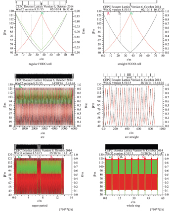
Fig. 3. Lattice functions in the booster.
Download figure:
Standard image High-resolution image3.3. Bypasses
Two identical bypasses are arranged in the booster to make the beamline skirt the detectors at IP1 and IP3 of the collider. The structure of a half of each bypass is indicated below.

Download figure:
Standard image High-resolution imageAs seen above, the bypasses are also based on FODO cells. The idea of the booster bypass design is to move out 3 regular FODO cells from the arcs to the bypasses and keep the straight sections BPI1 and BPI2 dispersion free. The advantage of this design is that no additional bending magnet is required and the energy losses due to synchrotron radiation keep the same as without bypasses. The length of a bypass is Lbp = 2 × (6+4f1 + 1.5f2) · Lc and the width of the bypass is Wbp = (9.5 + 9f1) · θcLc. By properly choosing the factors f1 and f2, both length and width of bypasses can be adjusted to meet the length of the interaction region and the detector width. In the present design, we take f1 = 1.0 and f2 = 1.0, giving a bypass width of 13.0 m and total length of 2 × 820 m, and the circumference of the booster is about 0.5 m longer than the collider.
The lattice functions in the long straights in IP2 & IP4 and half bypass in IP1 & IP3 are shown in Fig. 4. The beta functions keep regular, while the dispersion function is well suppressed in the straight sections.
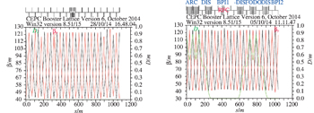
Fig. 4. Lattice functions in long straights in IP2 & IP4 and half bypass in IP1 & IP3.
Download figure:
Standard image High-resolution image3.4. Dynamic aperture
The dynamic aperture of the booster is studied with the optics computing code SAD [4]. Two families of sextupoles SF and SD near the quadrupoles QF and QD in FODO cells are used for chromaticity correction with corrected ξx = ξy = 0.5. Figure 5 plots the dynamic aperture for particles of Δp/p=0, ±1%, ±2% by tracking of 3 damping times assuming the transverse coupling r = εyεx = 0.01. Shown in the figure, the dynamic aperture for 0 and ±2% momentum errors is about 15σx × 130σy and 10σx × 100σy respectively, which is still critical for the stable operation of the booster. Further study is being carried out with more sextupole families and different configurations in the case of magnetic errors with more turns of particle tracking.
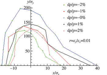
Fig. 5. Dynamic aperture plot.
Download figure:
Standard image High-resolution imageAs a summary of this section, the lattice-related parameters of the booster are given in Table 4.
Table 4. Lattice parameters of the booster.
| parameter | unit | value |
|---|---|---|
| FODO cell length | m | 71.665 |
| total number of FODO cells | 764 | |
| phase advance in a cell (H/V) | 60°/60° | |
| length of D/Q/S magnets | m | 8.0/1.0/0.2 |
| maximum β function (H/V) | m | 123.8/123.0 |
| transverse betatron tune (H/V) | 127.2/127.3 | |
| maximum dispersion function | m | 0.879 |
| length of bypass | m | 1640 |
| width of bypass | m | 13.0 |
| emittance (H/V) | nm·rad | 20.5/0.205 |
| damping time (Trans./Long.) | ms | 15.6/7.8 |
| momentum compaction factor | 10−5 | 7.69 |
| beam energy spread | % | 0.127 |
| synchrotron oscillation tune | 0.32076 | |
| bunch length (Vrf = 5.12 GV) | mm | 2.66 |
| maximum beam size (H/V) | mm | 1.948/0.159 |
4. Low injection energy issues
It is seen in Table 1 that the bending field of the booster at injection energy of 6 GeV is as low as 30.7 Gs, about 1/7 of the injection field of LEP [5]. The question is if the magnetic field is stable enough at such a low field against the earth's field of 0.5–0.6 Gs and its variation. To mitigate the low field problem, effort is also made to increase the bending field at injection with the proposed wiggling band scheme. Moreover, the beam instability at 6 GeV is discussed.
4.1. Low field stability test
Taking advantage of the existing BEPC bending magnet and power supply, low magnetic field stability was tested. The stability of the power supply was better than 1×10⁻⁴. A hall probe system was used for field measurement with accuracy of 0.1 Gs or ΔB/B of 3×10⁻³. The setup for the test is shown in Fig. 6.

Fig. 6. The magnetic field test setup.
Download figure:
Standard image High-resolution imageThe test was performed by Zhuo Zhang of the IHEP magnet group. The magnetic field outside and inside the magnet with zero excitation current was measured first. As shown in Fig. 7, the earth's field (outside the magnet) is about 0.8 Gs, with Bx = 0.55 Gs (south-to-north), By = 0.45 Gs (vertical) and Bz = 0.25 Gs (east-west); while the field inside the magnet is dominated by its residual field, one order of magnitude higher than the earth's field.
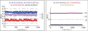
Fig. 7. Measured field outside (left) & inside (right) of the magnet.
Download figure:
Standard image High-resolution imageThe 24-hour magnetic field stability was measured for different excitation currents, as shown in Fig. 8.
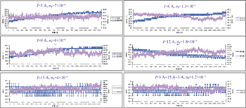
Fig. 8. 24-hour magnetic field stability test for different excitation currents.
Download figure:
Standard image High-resolution imageThe test shows that the magnetic field stability around 30 Gs is about 1 × 10⁻³, which indicates the injected beam energy for booster of 6 GeV could be feasible in view of field stability.
4.2. Wiggling bend scheme
The idea of the wiggling bend scheme comes from wiggler magnets applied in synchrotron radiation facilities where higher field cancelation makes zero or lower integrated field. The proposed scheme is shown in Fig. 9. There are four bending magnets in a half cell of the booster. Two outside bends are excited by a bipolar power supply making the wiggling bands so that the operating magnetic field gets higher.
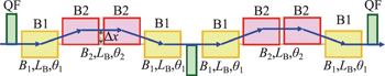
Fig. 9. The magnetic field test setup.
Download figure:
Standard image High-resolution imageThe magnetic field of the bending magnets is properly set during energy ramp to keep the total bending angle constant, i.e. θB2 + θB1 = 2θB. In principle, the oppositely excited bends B1 can be as low as −0.9Bej at injection for B2 = Bej. However, the orbit offset Δx = θ1 × (LB + LD) may get too large, where LB and LD are the lengths of the bending magnets and the drift space between the magnets respectively. Here we take B1 = −0.1Bej = 60 Gs, and B2 = 0.2Bej, i.e. double the magnetic field of the baseline design with Δx = 20 mm. The magnetic field and energy ramping curves are given in Fig.10.
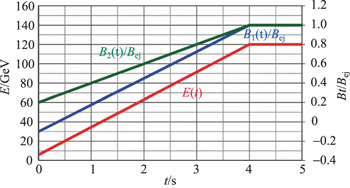
Fig. 10. Magnetic field and energy ramping curves in wiggling bend scheme.
Download figure:
Standard image High-resolution image4.3. Instability issue
The low injection energy not only results in low magnetic field, but also beam instability. The beam energy in the booster at injection is 1/20 of that in the collider, while the beam intensity in the booster is also 1/20 that of the collider. However, beams may get unstable for almost no synchrotron radiation damping in the booster. The special concern is for transverse mode coupling instability, coupled bunch instability excited by high order modes in 1.3 GHz superconducting cavities, and the resistive wall effect. A study on beam instability in the booster is in progress. In any case, a bunch-by-bunch feedback system should be equipped in the booster to provide a damping mechanism in order to stabilize the beams.
5. Beam transfer and injection
The 6 GeV electron and positron beams from the linac are injected into the booster ring through the transfer line LTB, accelerated to the top energy of 120 GeV and then extracted to the collider through the transfer line BTC.
5.1. Beam transfer from linac to booster
The transfer line LTB brings electron and positron beams from the linac to the booster and match to its phase space. The layout of the LTB is illustrated in Fig. 11.

Fig. 11. Layout of beam transfer line LTB.
Download figure:
Standard image High-resolution imageAs shown in Fig. 11, the transfer line LTB is comprised of a vertical slope line (VSL), a switch yard and e+e− branch lines. The vertical slope line connects the linac, which is at ground level, to the booster 50 m deep. It consists of a bend down section making a 1:10 slope, successive 15 straight 90° FODO cells and a bend down section making the end of the VSL dispersion free. The switch yard matches the Twiss parameters with the VSL and delivers the electron and positron beams to their individual branch lines. In the e+ and e− branch lines, beams are transferred in two arcs and then matched to the booster through the final matching sections. Each arc contains 2 dispersion suppressors and 6 regular 90° FODO cells. The dispersion suppressors are carefully arranged to avoid conflict of the magnets in the two branches. The lattice functions in the transfer line LTB are shown in Fig. 12.

Fig. 12. The lattice functions in the transfer line LTB.
Download figure:
Standard image High-resolution image5.2. Beam injection to booster
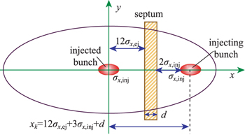
Through the transfer line LTB, electron and positron beams are injected into the booster from outside the ring. A horizontal septum is used to bend beams into the booster, and a single kicker downstream of the injected beams kicks the beams to the booster orbit with a maximum injection rate of 100 Hz. Figure 13 pictures the injecting bunch in the septum and the injected bunch in the booster. The kicker needs to deflect the beam with a displacement of xk = 12σx,ej+3σx,inj+d at the entrance of the septum in order to avoid particle loss of both injecting and injected bunches.
Fig. 13. Injecting and injected bunches at entrance of the septum.
Download figure:
Standard image High-resolution image
The main parameters of the injection septum and kicker are listed in Table 5. The strength of the septum and the kicker correspond to the energy of 12 GeV for future upgrade.
Table 5. Main parameters of the injection components
| magnet type | length/m | θ/mrad | field/T | aperture | |
|---|---|---|---|---|---|
| H/mm | V/mm | ||||
| septum | 2.0 | 9.1 | 0.18 | 41.4 | 13.4 |
| kicker | 0.5 | 0.40 | 0.032 | 41.4 | 13.4 |
6. Summary
The pre-conceptual physical design study on the CEPC booster described in the above sections finds no showstopper from the point of view of lattice, bypasses, dynamic aperture, beam transfer and requirement to technical systems. However, the issues related to the low energy injection, including the low magnetic field performance and beam instabilities, remain a central concern in the design. The earth's field effects and its shielding need to be studied to confirm if the booster can be operated at such low injection energy and low magnetic field. The wiggling bend scheme is proposed to mitigate this problem, while schemes of extending the linac injector with damping rings and adding a pre-booster are being considered. The feasibility of the wiggling bend scheme is being investigated taking into account the beam physics and technical rationality. There are some technical challenges in the booster, such as the low HOM 1.3 GHz SC cavities, supports & alignment, as well as low cost components. The design study needs to be developed further in more detail.
The author would like to thank all members of the CEPC design team for their perfect collaboration.