


Abstract
A simple, thin, flexible mantle cloak for conducting rods based on scattering cancellation is analyzed, designed and experimentally realized. We show strong scattering suppression at all angles of incidence, for both far-field plane-wave and near-field Gaussian excitations. The required effective shunt surface impedance is realized by a subwavelength patch array, targeting the suppression of the dominant omnidirectional scattering contribution of a conductive rod. Full-wave simulations predict a total radar cross-section reduction better than 14 dB in the lossless case and nearly 8 dB when considering a lossy substrate in the cover. Measurements of the realized cloak are consistent and validate these numerical predictions. The proposed geometry is also shown to be an ideal platform for monolithic integration of varactor diodes, allowing real-time tuning of the effective surface capacitance of the cloak. We show with numerical simulations the possibility of tunable scattering suppression over 1 GHz of bandwidth by seamlessly integrating varactor diodes in our mantle cloak design.
Export citation and abstract BibTeX RIS

Content from this work may be used under the terms of the Creative Commons Attribution 3.0 licence. Any further distribution of this work must maintain attribution to the author(s) and the title of the work, journal citation and DOI.
1. Introduction
In recent years, there have been significant advances in the ability to cloak objects and make them less detectable at radio frequencies [1–18,39]. Several techniques are currently available to reduce and/or disguise objects, with fundamental differences and their own advantages, generally trading bandwidth, electrical size, polarization, angle of incidence, and/or design complexity [19, 20]. A general distinction can be made based on the type of cloaking cover used to achieve this reduction in visibility, i.e., wave tailoring or scattering cancellation. In the latter category, ultrathin metasurfaces have been shown to be very effective in reducing the total scattering cross-sections of spherical and cylindrical objects suppressing, by destructive interference, the scattering from the object they are covering [6, 13, 21, 22]. Advantages of these mantle cloaks include their conformability, simplicity of manufacturing, resiliency to losses and tolerance to disorder, competitive bandwidth, potential for dual-polarized operation and electronic control [16, 18, 23].
Mantle cloaks are typically formed by a thin dielectric layer with subwavelength conductive patterns printed on its surface, essentially forming a printed circuit board (PCB) cover. Conventional metals can be used for the conductive traces at radio frequencies. However, the possibility of using atomically–thick graphene metasurfaces at low THz frequencies has also been explored, allowing for tunable cloaking of both conductive and dielectric objects [24, 25]. Mantle cloaks achieve a significant reduction in the visibility of objects of moderate electrical size by the cancellation of their dominant scattering orders, nearly restoring the incident field all around the object, even in its very near field. The scattering harmonics characterizing electrically larger objects become increasingly complex, and therefore a single-layer mantle cloak may not be sufficient to efficiently hide large structures, and multi-layered or anisotropic cloaks may become necessary [11, 14, 23]. It should be stressed however that exciting applications may potentially benefit from cloaks that are not necessarily electrically large, especially at lower frequencies, e.g., for antenna systems.
The operation of mantle cloaks is in stark contrast with more conventional stealth technologies, which are based on minimizing back reflections, rather than eliminating the total scattering, including shadows. Radar adsorbing materials are also well suited to reduce the monostatic radar signature, but both techniques may be defeated by bistatic measurements, due to significant forward scattering. On the contrary, mantle cloaks aim to cancel scattering in all directions via interference. It is evident that it is easier to suppress scattering and shadows for penetrable objects, such as those made of dielectric materials, while conductors create more challenges, due to their impenetrability. For this reason, to date mantle cloaking has been experimentally verified only for dielectric objects. In this paper, we demonstrate an optimized mantle cloak for finite-length conducting rods targeted for the transverse-magnetic polarization component that dominates its scattering signature.
In this section, we first derive an analytical solution for the two-dimensional (2D) radar cross-section (RCS) of infinitely long conducting cylinders excited by normally incident electromagnetic waves. For the target considered here, of moderate electrical cross-section, scattering from a normally incident field aligned along the cylinder axis is the most relevant form of excitation. The scattering from transverse-electric (TE) waves is significantly lower (in this case  ) than for transverse-magnetic (TM) excitation and, therefore, we focus on this polarization. We theoretically analyze the 2D scattering width for infinite cylinders even though in our experiment we consider a finite-length rod, since its length is much larger than its cross-section [26, 27]. In both simulations and experiment, the end effects and finite length of the conducting rod present their own challenges compared to the ideal 2D (infinite) scenario. Yet, the optimized mantle cover is shown to be able to significantly suppress the scattering of this more realistic case at all angles. Our analytical model is confirmed by full-wave simulations, and near- and far-field measurements on the finite-length rod [28]. Oblique far-field measurements are also performed to test the performance of the cloak for different excitations, backed by full-wave simulations to demonstrate a significant and stable scattering suppression all around the covered cylinder, and for bistatic scenarios. Losses are also investigated, revealing that the overall cloaking mechanism is rather robust, and material absorption mainly affects the scattering in the shadow region of the target, as predicted by the optical theorem. Finally, we envision the introduction of realistic varactor diodes in the designed mantle cloak, given its ideal compatibility with PCB components, allowing for real-time tuning over a large bandwidth. Active control offered by electronic covers is expected to extend the functionality of these devices, not only for camouflaging and scattering suppression, but also for electromagnetic wave control, beam-forming and energy harvesting.
2. Theoretical analysis
2.1. 2D circular cylinder
In this section we analyze the scattering from an infinite conducting cylinder of radius  surrounded by a mantle cloak of thickness
  . The geometry and coordinate system under analysis are shown in figure 1, which shows an arbitrary impinging plane wave incident with angle
  measured from the cylinder axis
  in vacuum
  under an
  time convention. A 2D cross-section of the geometry is shown in figure 1(b). The conductive cylinder is assumed to be covered by a dielectric shell coated with an ultrathin patterned conductive layer, and its finite-length realization, analyzed in the following section, is shown in figure 2.
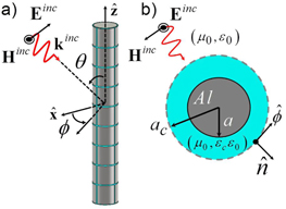
Figure 1. Schematic of a covered cylindrical rod by an arbitrary magnetodielectric metafilm. (a) Coordinate system used in this work for obliquely incident planes. (b) 2D cross-section of a circular cylinder covered by a mantle cloak.
Download figure:
Standard image High-resolution image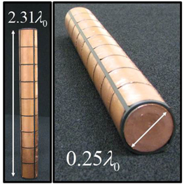
Figure 2. The realized cloak surrounding an aluminum rod. Here  = 3 GHz (
 ). For this design, the patch array has patch side
  , gap space
  , and the cloak thickness is
  .
.
Download figure:
Standard image High-resolution imageSince the thickness of the conducting cylinder and the metasurface are much larger than the skin depth at microwave frequencies, they may be well described as perfect electric conductors (PEC). Dielectric or conductive losses can be taken into account considering the loss tangent ( ) and surface resistance [29], respectively. The dielectric layer provides insulation between the center conductor and the patterned conductive surface, and the choice of layer thickness and permittivity (
 ) is influential on the overall cloaking effect, bandwidth, loss, and realizability.
Since the patterned metal thickness and granularity are smaller than the wavelength of operation, we model the coating as a uniform impedance surface [6, 30, 31] across which the tangential electric field is continuous, i.e.,  and satisfies

Equation (1) provides the relationship between tangential electric and magnetic fields on the anisotropic shunt surface impedance  surrounding the cylinder. This anisotropic impedance tensor can effectively model realistic deviations from an ideal isotropic cover, including the insurgence of polarization coupling. Even for normally incident TM plane waves, some cross-polarization coupling is expected, due to the granularity and possible asymmetries in the cover design; however, this effect is most visible at oblique incidence angles, for which it occurs even for ideally symmetric objects [26, 27]. The level of cross-polarization coupling depends on the complexity and number of subwavelength elements for a chosen surface, and it may be minimized by using simpler covers [22]. Using a square patch array, for instance, we may safely assume minimal polarization coupling and other non-ideal effects at normal incidence, which allows treating the surface impedance as a scalar
  .
.
Under this assumption, the total scattering width (SW) of the cylinder may be determined by the contribution from the most relevant scattering orders of the expansion:

where  is the Kronecker delta and
  is used in the following, which is sufficient for the size of the considered rod. Here,
  are the electric scattering multipoles due to a normally incident TM plane waves, derived from Mie theory and written in the compact form
  , where the determinants
  and
and  can be obtained using an analysis analogous to the one described in [6, 13, 21]. Similar considerations apply for TE scattering contributions; however, here the TE scattering harmonics are negligible, since we consider conducting cylindrical targets of moderate electrical cross-section (
 , where
  is the free-space wavelength of operation), and are anyway not excited for normal TM incidence. Under these conditions, the omnidirectional scattering mode
  is the most significant term. Therefore, by properly tailoring a single cover, we may be able to significantly reduce the overall SW, leaving only higher-order residual and more directive scattering modes.
Consider now an infinite conductive rod with cross-section  at 3 GHz covered by a lossless dielectric shell (
 ) of thickness
  . Figure 3 shows the surface reactance (black line) required to cancel the dominant scattering order, calculated using equation (2). A suitably designed metasurface can synthesize the required surface impedance at the frequency of interest
  , but it can meet the required reactance only at a single frequency, given the negative dispersion of the required impedance that would violate Foster's reactance theorem. This is consistent with the discussion in [16], which shows the necessity of non-Foster (active) metasurfaces to be able to track the required surface reactance dispersion over a broad bandwidth. In the figure we also show an ideal dispersionless cover that meets the required reactance at the figure of interest (red dotted line) and the one of a realistic patch array (blue dashed line) for an infinite (2D) cylinder, which synthesizes the required surface reactance at the design frequency, but that has a positive dispersion. The corresponding scattering widths for these three scenarios are shown in figure 4. Specifically, the figure shows the SW of the bare cylinder (solid black line) and of the same object after applying the ideal isotropic cover with dispersionless surface reactance
  , tailored to meet the condition
  . Scattering resonances are visible at higher frequencies, when
  . These resonances are somewhat intensified since losses are not considered in this figure, but they are consistent with the general theorem derived in [32] that requires the overall scattering of a cloaked object, when integrated over all frequencies, to be necessarily larger than the uncovered object. This implies that, while we are able to suppress the scattering at the target frequency, we are necessarily forced to distribute it at other frequencies. We also show in figure 4 the response of an ideal non-Foster surface
  that tracks the required surface reactance and significantly reduces the scattering across our band of interest. Such an active surface was first envisioned for dielectric rods in [16] and may be synthesized by loading the metasurface with negative impedance converter elements (NIC).
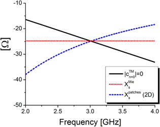
Figure 3. Required surface impedance of the mantle cloak to suppress the scattering of an infinite PEC cylinder (black solid line); surface impedance of a realistic dielectric-backed metasurface (blue dashed line) and of an ideal dispersionless cover (red dotted line).
Download figure:
Standard image High-resolution image
Figure 4. Calculated scattering width per unit length of the bare and covered 2D cylinder. The realistic passive cloak design (blue dashed line) is compared against a non-dispersive surface reactance (red dotted line in figure 3), and an ideal non-Foster metasurface (magenta circles).
Download figure:
Standard image High-resolution imageAny of the proposed metasurfaces produce a clear scattering dip at 3 GHz in figure 4, at which the omnidirectional scattering term is nullified by the capacitive surface. The required reactance may be realized with different metasurface geometries, such as Jerusalem crosses, cross dipoles, horizontal strips, or patch arrays [22]. A passive patch array is chosen here for its simplicity, bandwidth performance, and design flexibility, with the possibility of using asymmetric patches for dual-polarization operation [23] and the possibility of easily loading it with circuit elements to potentially realize a non-Foster response. As a starting point for the design, the required capacitive value  is synthesized based on an analytical model available in the planar case, with patch periodicity
  separated by gaps
  , and dielectric backing
  [22, 30, 31],
It is important to notice in (3) that there is no angle dependence for this averaged description of the dielectric-backed patch array for TM polarized wavefronts, since this model is based on a simplified dominant Floquet analysis [22, 30, 31]. When applied to the cylinder, the curvature and presence of a close-by ground plane is expected to introduce parasitic effects, modifying the surface response.
The blue dashed curves in figures 3 and 4 show the calculated dispersion of the corresponding surface impedance and scattering width for this metasurface. Not surprisingly, the scattering reduction in this realistic scenario is narrower in bandwidth than in the dispersionless scenario (red dotted curve), due to the fact that its reactance diverges more quickly from the required value for frequencies different than  . However, the possibility of actively loading such a surface is expected to dramatically extend the bandwidth of such passive covers, as shown in the non-Foster case. We discuss circuit loaded metasurfaces in the closing section of this paper.
2.2. 3D finite-length rod in free-space
Here we apply the previous theoretical results to the problem of cloaking a 3D conducting rod of length  . The finite length introduces obvious differences compared to the infinite case, mostly associated with end effects and longitudinal standing-wave resonances of the rod. The surface impedance
  , calculated by Mie theory (2), to suppress the scattering from an infinite cylinder (cf figure 2) is therefore not expected to be the same impedance required in the case of a finite-length rod. While Mie theory can provide good physical insights into the type of cover needed to suppress the scattering from dielectric and conductive rods of finite length, design refinements and optimization are required to minimize the total RCS of finite length rods, using the analytical results of the previous section as starting point.
In figure 5, we show the results of our optimization around the design formula (3), which leads to a patch array with dimensions  ,
,  ,
,  , backed by a flexible dielectric spacer with
  , capable of suppressing the scattering of our finite-length cylinder. In the figure we plot the total integrated RCS of the bare and covered object, showing large scattering suppression, over 14 dB (96%) at
  . Figure 6 shows the calculated effective impedance across the band of interest for the optimized planar patch array, and compare the results extracted from full-wave simulations to the closed-form analytical model in (3). The effective surface impedance of the planar array is extracted using a simple transmission line approach, where the infinite planar array is represented by a shunt impedance (in the inset of figure 6) [31]. The comparison between (3) and the extracted impedance is excellent, especially at lower frequencies, due to the large patch density.
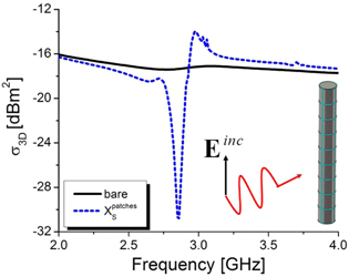
Figure 5. Total integrated 3D RCS for a bare conductive rod of length  (solid black line), and for the mantle cloaked object (blue dash dot).
Download figure:
Standard image High-resolution image
Figure 6. Extracted surface impedance (blue dash dot) using the transmission-line model in the inset and analytical (black open circle) comparison for the optimized 3D cover at normal incidence. Here the infinite planar surface impedance is  at 2.9 GHz.
Download figure:
Standard image High-resolution imageFigure 6 essentially shows an estimate of the required surface impedance for the finite length rod, which is seen to be quite different from the one of the infinite case at the design frequency. The required additional surface capacitance is associated with the additional scattering produced by the rod truncation and the associated current distribution induced on the object. We have indeed verified that the finite-length bare cylinder scatters comparatively more than the infinite geometry. In comparison, our previous work on dielectric rods [13] showed that the infinite cylinder scenario provided a description closer to the finite-length case. It appears that the conductive cylinder provides additional challenges in this 3D case, which are addressed by fine tuning the analytical design with proper optimization.
To provide further insights into the scattering suppression mechanism of the optimized cover, figure 7 shows the calculated three-dimensional scattering patterns with and without cloak for a finite-length aluminum rod of length  at the design frequency 2.9 GHz. As evident in the figure, the bare rod (panel a) scattering is dominated by the omnidirectional TM harmonic (
 ); however, other scattering modes are clearly present due to its moderate cross-section and finite length. When covered by the optimized lossless mantle cloak (b), a strong suppression of this scattering term leaves a much reduced residual scattering, formed by a superposition of higher-order scattering harmonics. Panels (c–d) consider the presence of losses in the dielectric spacers, using realistic material models: low-loss ceramics or flexible dielectrics [33, 34] (c), and flexible Neoprene (d). In all cases we included the realistic finite conductivity of copper and aluminum. By integrating the calculated patterns we obtain a total 3D RCS respectively of: (a)
  = −17.2 dBm2, (b)
  = −31.3 dBm2. In the lossy examples, the scattering reduction is slightly worsened to (d)
  = −24.9 dBm2, with larger contributions in the shadow region. This is fully consistent with the forward scattering theorem and power conservation, as the presence of absorption inherently requires an increase in forward scattering. These effects are further illustrated in figure 8, which considers the most relevant H-plane cut (cf figure 1
  ). For low-loss covers, the scattering suppression all around the cloak is excellent, even in the forward direction, i.e., the cloak allows restoring the impinging field distribution even in the back of the obstacle. In the case of larger dielectric loss in the cloak spacer, the shadow is increased due to absorption, while the mono-static cross-section (
 ) decreases. Nevertheless, even with this lossy dielectric spacer we achieve an overall scattering suppression of nearly 8 dB, further showing the mantle cloak's resiliency to loss. As noticed in [35], this is due to the inherent robustness of scattering cancellation techniques, which are inherently non-resonant in their operation.

Figure 7. Calculated total 3D RCS patterns for a finite-length bare (a) and covered (b–c–d) aluminum rods at  . Panel (b) considers a lossless dielectric spacer, (c) one with
  , and (d)
  . The finite conductivity of copper and aluminum are considered in all cases. Notice here the plots are in a dB scale. The residual scattering of the covered rods would be barely visible in a linear scale.
Download figure:
Standard image High-resolution image
Figure 8. Consistent with figure 5, H-plane RCS cut comparison for different levels of dielectric loss at  . Realistic low-loss covers are found to only marginally affect the cloaking all around the covered cylinder, while large dielectric absorption (losses) create a larger, but still reduced, shadow behind the covered finite length cylinder.
Download figure:
Standard image High-resolution image3. Experimental verification
In this section, we validate our theoretical and numerical results with 3D free-space near- and far-field measurements of our realized mantle cloak applied to the finite-length dielectric rod. Figure 2 shows the realized prototype of the thin metasurface cover surrounding the aluminum cylinder under test. A 1-mm-thick Neoprene cover was used to support the cloak, as considered in figure 7(d). Despite its losses, this material was selected due to its easy conformability and flexibility. The metallic patterns were realized with copper tape adhered to the Neoprene layer. This cloak design highlights several advantages in terms of simplicity and practicality, rather than bulky or complex metamaterial designs [3, 12]. The flexibility and conformability of the cloak may be naturally extended to more complex geometries. Such a design also offers the benefit of easy integration with electronics, in order to create flexible control of the scattering signature, as well as broadening the bandwidth, or allowing for tunability of the scattering cancellation effect [16, 18].
3.1. Near-field measurements
Our near-field measurements show strong scattering suppression and near-complete restoration of non-uniform incident wavefronts excited by a 10 dB gain horn antenna placed close to the target  . These measurements were conducted by raster scanning the transverse electric field throughout a plane at the central height of the cylindrical target. A highly repeatable (30 micron resolution) automated robotic arm, with a short electric field probe was programmed to take field measurements with a spatial sampling resolution of
  , and over a scan area of
  . For more details of our robotic arm scanner setup, see [10, 13, 36]. Figures 9 and 10 show the measurements of three different test scenarios (free space, bare, and covered) at 2.98 GHz and 2.84 GHz for normal (
 ) and oblique (
 ) incidence, respectively. Normal incidence is chosen as our original excitation geometry, which ensures maximum scattering signature for the bare cylinder. We also show results for
  incidence to show the robustness of the cloaking mechanism to variations in excitation. Our E-field probe samples the total field around the cloaked and uncloaked object, showing excellent restoration of the impinging fields and shadow suppression, even in very close proximity to the object. In the boxed regions of each panel the probe scans the field directly above the device, explaining why these measurements appear out of phase with respect to the rest of each image. Raw complex transverse electric field data are imaged with arbitrary units in figures 9 and 10 to highlight the differences of the fields for each of the test scenarios. To illustrate this cloaking effect, a free space measurement is shown in the left column, with the bare (center) and covered (right) cases. It is clear that the incident field is well restored all around the cloaked object, making the device much less detectable, even in its very near field. It is particularly impressive to realize that the cloak was designed for a far-field plane-wave at normal incidence, and yet it performs well in our near-field experiments, despite the change in excitation, the potential for near-field coupling between horn antenna and object under test, and the fabrication errors of our in-house realization.
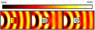
Figure 9. Snap-shot in time of the measured transverse electric field distribution for each scattering scenario (free space, uncloaked cylinder, cloaked cylinder) for a normally ( ) incident Gaussian wave from the left.
Download figure:
Standard image High-resolution image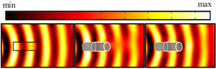
Figure 10. Snap-shot in time of the measured transverse electric field distribution for each scattering scenario (free space, uncloaked cylinder, cloaked cylinder) for an obliquely incident ( ) Gaussian wave from the left.
Download figure:
Standard image High-resolution image3.2. Far-field bistatic measurements
In order to further characterize the mantle cloak performance, we have also performed an extensive campaign of bistatic far-field measurements. Two ETS-Lindgren 3115 ultra-wideband microwave horns were placed equidistant (1.5 m) to the measurement setup [37]. For H-plane, bistatic measurements, one horn remained stationary, while the other was moved around the device under test in 20° steps, while keeping the distance constant. E-plane bistatic measurements were taken by keeping the horns stationary, but now moving the device under test about its axis in steps of 20°. By measuring the bistatic returns of our three tests (background, bare, and cloaked geometries, consistent with our near-field measurements), we are then able to estimate the level of RCS reduction, or scattering gain, by normalizing the cloaked RCS by that of the bare case. This normalization technique, along with conventional time-gating and vector background subtraction [13, 38], allowed us to compensate for the non-anechoic nature of our testing facility, as well as possible small calibration issues due to our test setup and environment.
Figure 11 shows the bistatic scattering reduction in the H-plane  in the back half space, comparing our measurements with full-wave simulations. Over 10 dB scattering reduction is shown with a highly stable frequency of operation. Notice that some of the sharp features seen in the simulations appear smoother in our measurements. This can be explained by the presence of dielectric loss in our prototype, as well as other fabrication imperfections, which tend to smooth the resonant response in the object. In our simulations we considered a low-loss dielectric spacer, to highlight the performance that may be achieved with lower loss. However, previous experience taught that exact matching of loss between simulation and experiment does not lead to better agreement, due to the larger effects of dimensional imperfections in manual construction [10]. As seen in the figures, despite losses, a strong and stable scattering non-resonant cloaking effect is clearly visible, and it matches our full-wave simulations well.
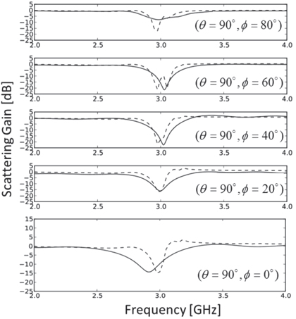
Figure 11. Bistatic scattering reduction in the H-plane for observation angles in the back half space. (Here and in the following figures, solid lines show the post-processed measurement data, and the dashed lines are full-wave simulations for the low-loss dielectric scenario).
Download figure:
Standard image High-resolution imageNext, we consider the scattering features in the forward H-plane direction (figure 12). There is a consistent 5.5 dB measured scattering suppression behind the cloaked conductive cylinder. This is quite impressive, also in light of the stable frequency response. We also consider oblique incidence angles for the back and forward scattering half-planes along the E-plane in figure 13  and figure 14
  . Strong and stable scattering reduction is still observed around the design frequency, confirming our far-field measurements and simulations, and the robustness to incidence angle of the cloaking phenomenon. The small detuning in the cloaking response for large incidence angles stems from the fact that the realistic anisotropic surface impedance has an inherent dependence on angle of incidence clearly not captured in (3). Yet, even in this worst-case scenario, the detuning is quite limited.

Figure 12. Bistatic scattering reduction in the H-plane for observation angles in the forward half space.
Download figure:
Standard image High-resolution image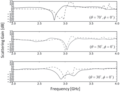
Figure 13. Oblique bistatic scattering reduction in the E-plane for observation angles in the back half space.
Download figure:
Standard image High-resolution image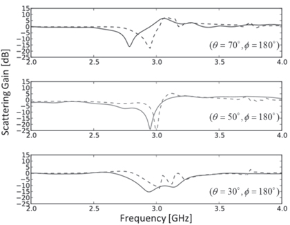
Figure 14. Oblique bistatic scattering reduction in the E-plane for observation angles in the back half space.
Download figure:
Standard image High-resolution image4. Tunability and reconfigurability using integrated diode varactors
The proposed metasurface technology is an ideal platform to introduce tunability and reconfigurability in the proposed cloaks by using electronic components (for a comprehensive review on reconfigurable devices at microwaves and THz, please see [41]). Recent efforts in embedding electronics into cloaking and illusion devices have indeed shown important advantages [16, 18, 42–44]. Electronically assisted cloaks using ideal varactor diodes have been recently explored in basic terms; however, the applicability of these concepts needs to consider realistic issues, such as parasitic effects and realizability constraints, since the cloaking effect is expected to be severely limited by these factors, especially for large multi-layered cloaks [45–46]. In this context, tunable plasmonic covers have been proposed using either electronic [47] or magnetic field biasing [48]. One benefit of the mantle cloak design considered here is its ability to easily integrate passive [18] or active loads [16], due to its inherent compatibility with conventional circuit components. In the following, we analyze the possibility of actively controlling the cloaking effect in frequency by loading the proposed metasurface cover with varactor diodes.
In general, a loaded patch (or horizontal strip) array is given by the parallel combination of the infinite sheet impedance in (3) and a given load impedance per unit length [31]. In particular, the equivalent impedance of a varactor diode is [49]
In equation (4), consistent with the inset of figure 15, a realistic varactor contributes packaging and die parasitics  , which de-tune the ideal junction capacitance
  and introduce a voltage dependent absorption (or loss). The realistic loaded surface impedance may be drastically simplified by considering an ideal model for a tunable capacitive sheet:

where  is the zero bias junction capacitance,
  is the gradient coefficient,
  is the reverse bias and
  is the junction potential, dependent on fabrication and doping [50]. As expected, this effective sheet model shows that we may tune the sheet reactance in real time by controlling the applied voltage on the varactors. Considering figure 3, this has the effect of sweeping the cloaking frequency for which the dominant-mode scattering is canceled.
In the following, we consider realistic varactor diodes, using the model (4), to tune the cloaking effect across a 1 GHz band centered at 3 GHz using the same cover as in our experiment (cf figure 2). For simplicity, we consider an air substrate for these simulations, to set the highest frequency of this sweeping range at our frequency of interest  . For this cloak design, we found that the SVM 1231 varactor with an SC-79 package provides the correct capacitance values 0.466 to 2.35 pF from 15 to 0 V applied voltage, respectively.
We have verified by full-wave simulation the tunability of the cloaking effect in this configuration, considering realistic parasitics, as shown in figure 16. Shown in the figure is the total RCS reduction with applied reverse bias  . Across the band of 2.4–3.4 GHz a strong total integrated scattering suppression of approximately 6 dB is reported. Simply adjusting the bias voltage, a significant reduction of over 75% is observed across a 1 GHz bandwidth. We are able to fully exploit the voltage range of the varactor diode (0 to 15 V) in order to reduce the scattering well below 2 GHz; however, for low reverse biases, diode losses reduce the suppression to around 3 dB.
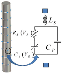
Figure 15. (a) Varactor-loaded patch or horizontal strip surface, and equivalent circuit model.
Download figure:
Standard image High-resolution image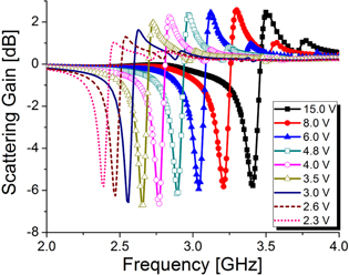
Figure 16. Total integrated scattering reduction with bias voltage for the tunable cloak conceptual design of figure 15.
Download figure:
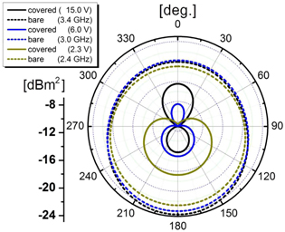
Standard image High-resolution imageIn order to fully appreciate the level of scattering suppression all around the electronically controlled cloak with reverse bias, we plot the patterns at the low (2.4 GHz), mid (3.0 GHz), and high (3.4 GHz) bands in figure 17, comparing in each case the bare and cloaked objects. We find that in the high-band the residual radiation pattern is mainly directed in the back direction (towards the observer), while the forward-directed (4 dB lower than in the back) scattering is almost completely canceled. At midband the opposite is true, with strong suppression all around, but with a small forward directed residual pattern. In the lowband, an interesting Huygens-like directive radiation pattern is observed, indicating a combination of residual electric and magnetic scattering modes of comparable strength [50]. By mapping the scattering dips in figure 16 to the applied voltages, we note that the mantle cloak design introduced here may be ideal to realize non-Foster frequency dispersion and achieve broadband cloaking, as discussed in section 2 and originally envisioned in [16].
Figure 17. Azimuthal radiation patterns with bias adjustment for the tunable cloak conceptual design of figure 13.
Download figure:
Standard image High-resolution image
5. Conclusions
We have designed and experimentally verified that a conformal, lightweight, simple mantle cloak, based on a patterned metallic surface, may substantially reduce the scattering of impenetrable objects at radio frequencies. In this work, a conductive rod's scattering signature was significantly reduced at all angles, confirming our theoretical insights and simulations with near- and far-field measurements. We have also verified through simulations and experiments that high dielectric losses have only a limited detrimental effect on the cloaking in the shadow of the target, due the mantle cloak non-resonant operation. Finally, through rigorous simulations we have shown that the cloaking frequency may be easily tuned with varactor diodes integrated into the mantle cloaks across a large bandwidth, even with parasitics. The mantle cloaking technique is foreseen to be of great impact for a variety of applications of interest to the antenna community, including antenna blockage and co-site interference reduction, energy harvesting, and radiation pattern synthesis and control [40, 51, 52]. This technology is well suited to be significantly enhanced by the use of integrated electronic technology, which may further increase its tunability, bandwidth, and possibly level of suppression [16–18].
Acknowledgements
JS and AA were supported by the National Science Foundation (NSF) CAREER award ECCS-0953311. DR and AK were supported by an internal research award at ARL:UT. The authors would also like to gratefully thank Rory Pilgrim for his assistance with the near-field imaging system.