Abstract
Artificial muscles powered by a renewable energy source are desired for joint articulation in bio-inspired autonomous systems. In this study, a robotic underwater vehicle, inspired by jellyfish, was designed to be actuated by a chemical fuel source. The fuel-powered muscles presented in this work comprise nano-platinum catalyst-coated multi-wall carbon nanotube (MWCNT) sheets, wrapped on the surface of nickel–titanium (NiTi) shape memory alloy (SMA). As a mixture of oxygen and hydrogen gases makes contact with the platinum, the resulting exothermic reaction activates the nickel–titanium (NiTi)-based SMA. The MWCNT sheets serve as a support for the platinum particles and enhance the heat transfer due to the high thermal conductivity between the composite and the SMA. A hydrogen and oxygen fuel source could potentially provide higher power density than electrical sources. Several vehicle designs were considered and a peripheral SMA configuration under the robotic bell was chosen as the best arrangement. Constitutive equations combined with thermodynamic modeling were developed to understand the influence of system parameters that affect the overall actuation behavior of the fuel-powered SMA. The model is based on the changes in entropy of the hydrogen and oxygen fuel on the composite actuator within a channel. The specific heat capacity is the dominant factor controlling the width of the strain for various pulse widths of fuel delivery. Both theoretical and experimental strains for different diameter (100 and 150 µm) SMA/MWCNT/Pt fuel-powered muscles with dead weight attached at the end exhibited the highest magnitude under 450 ms of fuel delivery within 1.6 mm diameter conduit size. Fuel-powered bell deformation of 13.5% was found to be comparable to that of electrically powered (29%) and natural jellyfish (42%).
1. Introduction
Nanotechnology and biomimetics have enabled the development of new devices and at the same time improving the functionality of existing devices. Biomimetics relies on how closely one can replicate biological systems with artificial materials that ultimately lead to enhanced functionality in engineering systems. Nanotechnology continues to play a key role in the development of novel biomimetic actuation mechanisms. Recently, emphasis has begun to be placed on bio-inspiration, where one learns the structure–function relationship in natural organisms and then develops technology with the objective of surpassing the performance observed in nature. One area of focus for bio-inspired technologies has been that of artificial muscles or actuators. High stroke—high stress—low power-consuming artificial muscles are the most important element in the continued development of bio-robotics and bio-mechatronics.
There has been continued advances in the area of artificial muscles [1–3]. Some of the systems that have been investigated include air-powered and pneumatic muscles [3], electrically actuated shape memory alloys [4–7], polymer actuator technologies [2] and carbon nanotube (CNT) actuators [8]. Several geometries and dopant compositions of polypyrrole actuators have been studied for various applications [9–15]. In addition to these electrically powered actuators, Ebron et al have reported chemically powered artificial muscles [16], where NiTi shape memory alloy (SMA) wires coated with catalyst platinum particles were actuated using hydrogen, methanol or formic acid as a fuel. In the presence of an oxidant, the NiTi SMA demonstrated high actuation strain (5%) and stress (∼150 MPa). Development of fuel-powered SMA actuator systems has been addressed by Jun et al [17].
Recently, composite actuator technologies such as bio-inspired shape memory alloy composites (BISMAC) [18] have been employed to achieve the desired actuation for biomimetic jellyfish applications. Jellyfish have gained significant interest for development of unmanned undersea vehicles (UUVs) for monitoring the ocean environment [18, 19]. It can be used for surveillance in both military and civilian applications. Attempts have been made to develop artificial jellyfish using different actuation technologies including ionic polymer metal composite (IPMC) and polypyrrole composite (PPy) [20, 21]. In this application, the actuator needs to create deformation characteristics similar to that of natural jellyfish, resulting in a wake structure that allows efficient and proficient swimming. Jellyfish are invertebrates with a relatively simple muscle structure consisting of radial and circumferential muscles [22–24]. They exist in a multitude of morphologies and exhibit two prominent propulsion mechanisms, termed 'rowing' and 'jetting' [25]. The advantage of using fuel-powered muscles in artificial jellyfish is the high energy capacity per weight over conventional means. In addition, the fuel-powered technology has the following benefits: (1) fuel power actuation is a 'green' technology that does not need batteries, (2) it has the potential to regenerate fuel from its surroundings and (3) it has the potential to develop new components that have access to gas flow or liquid fuels.
The vehicle used in this study is a modified version of the Robojelly described in Villanueva et al [26] and designed to integrate fuel-powered technology. The bell of the vehicle was 16.4 cm diameter and the same geometry as the Aurelia aurita medusa species. This animal consists of a uniform bell which is almost axisymmetric. The bell is the main part of the body, which is made mostly of mesoglea encased by a skin-like layer called the epidermis. The subumbrella, referring to the inner part of the bell, houses the circular muscles responsible for propulsion. As they contract, the bell closes on itself and ejects water to propel the body. The ejected water follows a complex interaction of starting and stopping vortices [27]. These vortices have been shown to play a crucial part in the efficiency of the animal's propulsion mechanism [25]. After contraction, the bell undergoes a relaxation phase where it regains its original shape passively using the elastic energy stored in the bell structure. In this study, particular attention was paid to the bell deformation of the robotic jellyfish. Villanueva et al (2011) [26] have shown that Robojelly is able to achieve a deformation of 29% at the inflection point while the natural animal achieves 42% deformation. These deformations refer to the bell displacement normalized by the curved length of the bell. Matching the natural deformation is the first step towards replicating the bell dynamics which will allow us to meet or exceed the propulsion efficiency and proficiency of the natural animal. The bell configuration used in this study is a segmented bell with flap configuration. The flap is a passive membrane that is attached around the active bell segment in order to replicate a similar structure to that found in natural jellyfish.
This paper is organized into six sections. Section 1 provides the introduction and background to artificial muscle based on a renewable energy source. Section 2 discusses the theoretical modeling of fuel-powered shape memory alloys and results from numerical simulation. Section 3 describes the synthesis and characterization of fuel-powered artificial muscle. Section 4 illustrates various designs of artificial jellyfish vehicle and testing under different environmental conditions. Section 5 compares the theoretical and experimental results and section 6 summarizes the current study.
2. Theoretical study on fuel-powered SMA
2.1. Modeling of fuel-powered SMA
The modeling of the fuel-powered SMA is based on a phenomenological approach and thermodynamic analysis. In our case, the power source is chemical energy and the heat generation is derived based on the entropy equation. A schematic diagram of the cut-out portion of the fuel-powered SMA is shown in figure 1.

Figure 1. Schematic diagram of the heat transfer in a MWCNT-wrapped SMA composite actuator. (a) Actuator with distinct material and (b) actuator lumped within a control volume shown in green.
Download figure:
Standard imageThe chemical reaction of hydrogen and oxygen producing water and heat (Q) as by-products is given by the balanced chemical equation

The chemical reaction of hydrogen and oxygen is similar to the chemical reaction in fuel cells. We can consider the system as a fuel cell and obtain the heat generated, Q, which activates the SMA. The minimum heat generated (heat rise) in a chemical reaction assuming isothermal conditions can be described by the product of the temperature and change in entropy of the reactant and product [29]. Therefore the heat rise can be written as

where T is the temperature at a given instant, and Sreactant and Sproduct are the entropy of the reactant and products, respectively. The entropy at different pressure (P) and temperature (T) of the gases assuming ideal gas is given as

where So(T) is the absolute entropy at temperature T and reference pressure Pref (1 atm), and R is the universal gas constant of 8.3145 (J mol−1 K−1). Therefore, the heat rise in the reaction of hydrogen and oxygen referencing the balanced equation (1) per mole of the fuel hydrogen can be written as

The rate of heat generation is simply the product of mass flow rate and the heat rise:
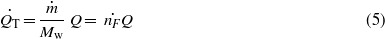
where is the mass flow rate of the fuel and Mw is the molecular weight of the fuel. There are several heat losses that can be accounted for in the modeling. These losses include radiation heat loss in the pipe and convection. The mechanism of heat rise in the SMA is due to conduction and convection but in this analysis the SMA and MWCNT were considered as a composite material and the material properties were derived based upon the rule of mixture of composite materials. The change in internal energy of the composite SMA, Pt and MWCNT can be obtained from heat balance as follows:


where cp is the specific heat capacity of the SMA and MWCNT, mc is the mass of the composite, Ts is the temperature of the composite, is the total heat generated due to chemical reaction and is the total heat loss which is the sum of (radiation heat loss) and (convection heat loss within the channel). The heat rise in the SMA is basically due to conduction () and heat transfer due to convection () across the Pt–MWCNT layer.


The conduction heat transfer for a one-dimensional cylindrical surface can be obtained as

where for a one-dimensional cylindrical surface with radius r1 and r2, and , Tg is the temperature at the instant the reaction occurs at the surface, Ts is the temperature of the SMA surface, k is the thermal conductivity of MWCNT, l is the length of SMA, d is the diameter of the SMA and tc is the thickness of the MWCNT and Pt wrapping. The convective heat transfer loss in the channel depends on the convective heat transfer coefficient (h), the surface area of the composite (A) and change in temperature:


The radiation heat transfer loss is given by

where δ is the Stefan–Boltzmann constant (5.6703 × 10⁻⁸ (W m−2 K−4)) and ε is the emissivity of the object (=1 for a black object). Normal spectral emissivity of a SWNT forest has been previously studied for a wide range of wavelengths between 5 and 12 µm and was found to be 0.98 [30].
The overall modeling of the fuel-powered SMA includes the constitutive relationship of SMA, dynamics and heat transfer. The general one-dimensional governing equation for a SMA actuator can be obtained from the constitutive relationship first proposed by Liang and Rogers [31] as

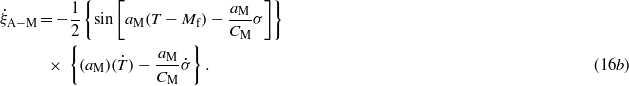
where σ, ε, ξ and T represent the stress, strain, fraction of martensite and temperature in the SMA actuator, respectively. The subscripts in each symbol represent the initial conditions. Further, E is Young's modulus, θ is the thermal expansion coefficient and Ω is the material transformation coefficient which can be obtained from the hysteresis loop of SMA (Ω = Eεl). The fraction of martensite represents the percentage of martensite during transformation. The value ranges between 0 and 1 (ξ = 1 for a fully martensitic phase and ξ = 0 for a fully austenitic phase). In SMA modeling, the average value of the modulus of elasticity for austenite and martensite in SMA provides a close approximation to predict the actuator response [32, 33]. In fact, the modulus of elasticity of the SMA actuator is dependent on the fraction of martensite and varies as the internal temperature state changes in time [34]. The modulus of elasticity can be written as


where Ea and Em are the modulus of elasticity of austenite and martensite, respectively. The fraction of martensite is one of the characteristic curves (hysteresis loops) of SMA. It is a function of temperature of the wire, the transition temperatures and the stress in the material. Generally, the equation can be obtained from kinetic law. The four characteristic temperatures—martensite start (Ms), martensite finish (Mf), austenite start (As) and austenite finish (Af)—are dependent on the stress level. Considering the austenite–martensite and martensite–austenite transformations as harmonic functions of cosines, the fraction of martensite with non-zero stress state can be expressed by (12) [35]
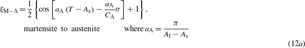
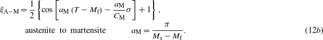
CM and CA are the stress influence coefficients for martensite and austenite. The conditions for the switching martensite fraction function are based on the enhanced phenomenological model [36, 37]. These conditions are basically dependent upon the stress, temperature and the rate form of stress and temperature in the SMA. The condition can be written as: martensitic phase

austenitic phase

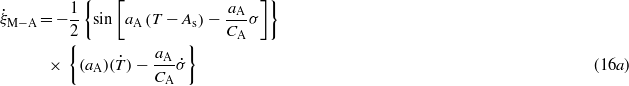
The stress influence coefficients, CA and CM, are the slope of stress and transformation temperature [5, 35]. The rate form of the constitutive relationship of the SMA actuator can be obtained by taking the first derivative of equation (10) given as

If the modulus, transformation coefficient and thermal expansion coefficient are assumed to be constant, equation (14) reduces to

The rate form of the martensite fraction can be expressed as follows:
The rise in internal temperature of the SMA due to the fuel input can be obtained from equation (6). Rearranging the terms and assuming the actuator as a lumped capacitance, the rate of change of temperature is given as
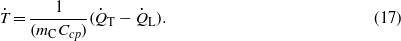
The specific heat capacity and mass of the actuators are taken by applying the rule of mixture for composite materials. The specific heat can be expressed as

where mC is the mass of the composite actuator (SMA and MWCNT), Ccp is the specific heat capacity of the composite, is the mass fraction of MWCNT, is the total heat input given by equation (5), QL is the heat losses and T is the temperature of the wire. The stress, strain, temperature and fraction of martensite are coupled and cannot be solved explicitly. However, the equations can be solved numerically. Simulink™ block diagrams were created to simultaneously obtain the state vector (stress, strain, fraction of martensite, input heat due to chemical reaction and temperature).


Another equation is required to solve the dynamic relationship. The dynamic modeling includes two configurations: (i) when the SMA is lifting a dead weight and (ii) when the SMA is actuating a leaf spring used for the bell segment. To model the bell segment actuation, the SMA is assumed to be attached with a simple spring with stiffness Kst. The well-known dynamic equation of motion, assuming damping (c), stiffness (k) and inertial mass (m) with external force applied starting from the equilibrium displacement point can be obtained as

where Asma is the cross-sectional area of the SMA actuator, σ is the stress in the SMA wire and x is the displacement of the tip mass attached to SMA. When the dead weight is suspended at the end of SMA and, if the SMA is not actuated, the wire serves as a spring whose spring constant can be determined from the standard spring stiffness of a cord. The spring stiffness can be obtained from relation , where A is the cross-sectional area of the wire, E is the modulus of elasticity which is the modulus of martensite (for no external heat applied) and L is the length of the SMA wire. However, when the SMA is actuated, it provides tension to the wire due to the stress generated and lifts up the weight attached at the end. A stiffness factor kf was used to emphasize or de-emphasize this assumption.

For the bell segment with spring steel embedded within the elastomeric substrate, a second-order dynamic equation similar to equation (19) can be written. The displacement can be replaced with rotational angle, the stiffness with torsional stiffness of the spring and the force with a torque due to the SMA:

where I is the moment of inertia, θ is the rotation angle, kt is the torsional stiffness, e is the eccentricity of the SMA in the composite and τsma is the torque due to the SMA.
To understand the parametric relationship, numerical simulations were performed. The simulations were performed for a dead weight attached to the artificial muscle (fuel-powered SMA). Table A.1 (in the appendix) summarizes the parameters used for the numerical simulation using a Simulink model that utilized the equations presented in this section.
2.2. Numerical simulation
Numerical simulations were performed to study the variation of various structural and material parameters that affect the strain response of fuel-powered muscles. As described in the modeling section, the heat generation is obtained from the entropy of the reactant hydrogen and oxygen accounting for changes in pressure and temperature. In order to reduce the complexity, radiation heat loss was ignored in the numerical simulation. The factors that affect the performance are listed in table A.1, namely, martensite start and finish temperatures, austenite start and finish temperatures, stress influence coefficients, heat capacity, density of the SMA and MWCNT, geometrical parameters (length and diameter), fuel properties and fuel inlet conditions (pressure and temperature). In order to account for the composite properties, the rules of mixtures were applied by obtaining the fraction of MWCNT and calculating the specific heat capacity of the composite as described in equation (18). The numerical values presented in table A.1 were utilized in a Matlab program and a Simulink model. The Matlab program was used to initiate the Simulink model, to automate the simulation and to obtain the state variables (stress, strain, temperature, heat, transformation temperatures and fraction of martensite). The Simulink model is shown in figure 2. The fuel input block provides the type of signals and pulse width of the fuel delivery to the heat transfer block with a signal generator function or from workspace function. Next, the output from the heat transfer block was provided to the phase transformation block which determines the transition temperatures in terms of the stress and temperature changes. At the same time, the output was provided to the constitutive block which consists of the constitutive relationship for SMA that outputs the stress rate (shown as ). The stress rate () is integrated to obtain the stress (σ) and then fed back to the phase transformation block and also to the dynamic block. The output of the dynamic block (strain rate) is connected to a constitutive block with Goto function. It should be noted that the governing relations, described in the modeling section, are transcendental and switching functions and can be solved by iteration using initial values. The input pulse width for fuel delivery was varied between 200 and 450 ms during the simulation period of 5 s in the fuel input block. The Simulink model presented here is similar to the electrically activated SMA described by Tadesse et al [6]. The difference between the Simulink model in electrically activated SMA and fuel-powered SMA is the addition of the fuel input block in place of an electrical source.


Figure 2. Simulink model of the fuel-powered SMA actuator.
Download figure:
Standard image2.3. Simulation results
The numerical simulations were performed using the parameters given in table A.1 (appendix) with a dead weight at the end and various pulse widths of fuel delivery. The results of the numerical simulations are shown in figures 3(a)–(c). The damping in the system is usually unknown, therefore the damping ratio, ζ was varied (0.1–11) and a stiffness coefficient kf was used to vary the contribution of the wire as a spring. The numerical simulations show that a small pulse width of fuel delivery (200 ms) provides a smaller strain than the higher pulse width (450 ms). This indicates that the heat generated did not bring about the change in temperature required to cross the transition temperature. Thus, the transformation of martensite to austenite is not fully complete (partial transformation was encountered). Intuitively, it can be understood that, if the heating is of short duration, the heat propagation to the SMA/MWCNT composite will be minimal. The decay of the strain is sharp for the majority of the simulation except at higher damping as shown in figure 3(b) which remains at remnant strain values at the end. As the damping increases the output strain decreases. The specific heat capacity of the composite affects the response time significantly. Numerical simulations were carried out to illustrate this effect and the results are shown in figure 3(d). The heat capacity which was determined by equation (18) was increased six times to account for the uncertainty of the parameter during simulation. From the figure, it can be seen that the width of the strain outputs is increased by a factor of 2.5 as compared with figure 3(a). A contour plot of damping value, stiffness factor (kf) and the maximum strain obtained at different fuel delivery times are portrayed in figure 3(d). From this figure, a difference of 200 ms fuel delivery exhibit relatively large changes in the maximum strain value change (a difference of 1.5%). A stiffness factor change from 0.4 to 1 also has similar maximum strain change for most of the fuel delivery time and damping values. A range of damping values does not have a significant effect, particularly at low fuel delivery times. In the contour plot, the curves with similar colors represent the same stiffness factor (kf), whereas various line styles (solid, dashed and dotted lines) represent variable pulse width of fuel delivery (pw). For example, a black solid line, black dashed line and black dotted line correspond to 450, 300 and 200 ms of fuel delivery while keeping the stiffness factor constant at kf = 0.4. The green, blue and red colored curves represent kf = 0.5, 0.8 and 1. The reason for illustrating this plot is to explain the change in maximum strain for two parameters: various fuel deliveries (pw) and the spring stiffness factor (kf) of the actuator. The result is highly dependent on the parameters described in table A.1. However, the simulation results provide insightful information in the design and characterization of fuel-powered muscle.

Figure 3. Numerical simulation result of the strain output of fuel-powered muscle with a dead weight attached at the end using values listed in table A.1 and the equations in the modeling section combined with Simulink model: (a) strain at low damping, (b) strain at high damping, (c) strain response for increased heat capacity by a factor of 6 and (d) the variation of maximum strain for variable pulse width of fuel delivery and stiffness factor kf.
Download figure:
Standard imageThe other state variables obtained from the numerical simulation are depicted in figure 4 indicating the relationship of the physical quantities. Figure 4(a) presents the heat generated (Q) during the delivery of hydrogen and oxygen at an absolute pressure of 1.212 atm for various pulse widths of activation. The strain output (ε), fraction of martensite (ξ), stress (σ) and temperature (T) are shown as a function of time in figures 3(a)–(e). In all cases, we can clearly see fuel delivery time playing a key role for the achievable strain magnitude. In fact, the strain generated is a function of several variables. For example, if the pressure is increased to 10 atm, it will not produce any strain because the generated heat will not propagate to the SMA. The temperature profile (figure 4(e)) is decaying monotonically according to the time constant. Figure 4(f) explains the transformation behavior of martensite with a hysteresis loop. The loop gets narrow for 200 ms fuel delivery than the 450 ms. At the 200 ms delivery, the percentage of martensite transformation is about 60% as compared to 100% for 450 ms. The temperature profiles as well as the four transition temperatures of SMA are shown in figure 7(g). In this figure a particular temperature can only bring about a strain whenever it crosses the transition temperature. In figure 7(g) we can see that the temperature generated due to 200 ms and 400 ms pulse of fuel (red color and black solid lines, respectively). The transformation temperatures for each fuel delivery time are also shown.

Figure 4. Numerical simulation result of fuel-powered SMA/MWCNT for various fuel delivery widths: (a) heat input, (b) stress, (c) martensite fraction, (d) strain and (e) temperatures variation in time. (f) Fraction of martensite as a function of temperature and (g) two typical temperature profiles crossing the boundary of transformation temperatures.
Download figure:
Standard image3. Experimental methods
3.1. Fuel-powered shape memory alloy muscle synthesis
The structure of artificial muscle comprises of commercially available SMA actuators wrapped with a composite of MWCNT sheets overlaid with catalytic platinum black powder. When hydrogen and oxygen fuel are delivered to the composite, the platinum catalyst initiates a reaction and the resulting exothermic heat activates the SMA. Thermal energy transferred by the chemical reaction causes strain in the SMA due to the phase transformation. MWCNT has a thermal conductivity as high as 150 ± 15 W m−1 K−1 [38] which enhances the heat transfer to SMA. The response time of this actuator is dependent on the thermodynamic reaction during injection of fuel and the evacuation in the cooling phase. A schematic diagram of the artificial fuel-powered muscle is illustrated in figure 5. The mechanism for driving these actuators with hydrogen and oxygen is shown in this figure. When hydrogen is exposed to finely divided catalytic platinum in the presence of oxygen, combustion becomes thermodynamically favorable. This combustion is used to provide the heat required for SMA to transition between the low temperature martensite phase and the high temperature austenite phase. An additional benefit of using purely hydrogen and oxygen as reactants is that the sole product is water.

Figure 5. Schematic diagram of the hydrogen-fuel-powered SMA actuator (dimensions are not to scale).
Download figure:
Standard imageWe have improved upon the previously reported designs [16, 39, 40] by adopting a significantly different approach. This involves the usage of MWNT sheets drawn from as-grown CNT forests described in detail elsewhere [41, 42]. The method utilizes a porous yet mechanically strong network of carbon nanotube bundles to hold finely divided Pt-black catalyst against the SMA wire. A drawing process was developed to produce CNT wires about 400 mm in length by using a semi-automatic lathe that allows radial spinning. When the wire is spinning on the lathe, a thin strip of carbon nanotube bundles draws itself along the wire, wrapping it like a porous tape. We use this process to our advantage by supplying a powder of platinum black catalyst that is stored inside this wrapping. Wires made in this fashion have been run for over 50 000 cycles with little or no degradation in stroke or cycle time. Scanning electron microscopy (SEM) was utilized to reveal the microstructure of as-synthesized artificial muscle wires. The results are shown in figure 6 at different magnifications, revealing that platinum black particles and agglomerations are confined, yet readily accessible, within the conduct CNT mesh. The experiments were repeated several times to confirm the repeatability of all microstructures.

Figure 6. Scanning electron micrographs of the artificial muscles at (a) 200×, (b) 1000× and (c) 5000×. (d) Fabrication of the artificial muscle.
Download figure:
Standard image3.2. Characterization
The NiTi wires consisting of Pt-black catalyst wrapped with MWNT sheets were tested to investigate performance under various fuel delivery conditions. The actuation of the wire was measured using a digital meter with respect to the time of fuel delivered by using electro-pneumatic valves. As shown in the schematic diagram of figure 7(a), we were able to identify the characteristics of the actuator by using a conduit size of 1.6 mm (1/16 in) inside diameter. After 450 ms of fuel exposure in sheet-wrapped wires, the strain to fuel usage ratio was found to saturate. These wires are capable of over 2.5% strain per cycle with a full cycle of less than 5 s using passive cooling. Compared to the electrical driving, our technique heats the wire from the outside inwards. This is expected to be the reason for lower strain magnitude since resistive heating can apply a more even heating profile to the wire. However, there are apparent advantages to our fuel-powered muscles. Noting that the energy density of a typical Li-ion battery is around 1 kJ g−1, which is much lower compared to that of hydrogen and oxygen gas contained in heavy tanks (5.6 kJ g−1). When using ambient oxygen as fuel, the energy density is even more favorable. Refueling the system is faster than recharging a battery and there is no charge/discharge lifetime for a gas tank as there is in the case of a rechargeable battery.

Figure 7. (a) Characteristic of 100 µm diameter and 150 mm long NiTi-wrapped Pt black with MWCNT sheet fuel-powered muscle. (a) Strain generated for various amounts of fuel delivery time under a conduit of 1.5 mm diameter. (b) Schematic diagram of actuation. (c) Energy density of various fuel options that can be used for actuation of the SMA.
Download figure:
Standard image4. Fuel-powered SMA vehicle design and testing
4.1. Vehicle design
Next we describe the method for implementing the MWCNT-based fuel-powered muscle in a jellyfish vehicle. First, a computer-aided design (CAD) model was generated to mimic the Aurelia aurita jellyfish profile that incorporated the essential features in using fuel-powered muscle. Various designs were considered to develop the overall system such that the thermodynamic efficiency of the process was maximized. The efficiency depends on the rapid transfer of generated heat to the SMA wire and subsequent cooling process. The first design was similar to previously developed artificial jellyfish actuated electrically in terms of both dimension and morphology (Villanueva et al). Eight BISMAC actuators surrounded the circumference and each segment included a channel which allowed the flow of hydrogen and oxygen (inlet system), and an exhaust system to remove the burnt fuel out of the tank. The flow was controlled by two solenoid valves. The mixture of fuel was delivered to each channel and the exhaust was collected in a storage tank and finally released to the outside environment. The main features of this design were: (i) the fuel channel was inside the silicone-based mesoglea, and (ii) the circular cross section of the channel. The major problem was frictional loss of catalyst to the silicone wall which limited the performance. The solution to this problem was varying the channel size for optimum performance. The channel diameter should not be large because it will limit the heat transferred to the SMA and, at the same time, it should not be small because the entire surface of the actuator will touch the silicone wall, limiting the cooling and deformation [18]. The second design was based on the notion that, if the channel is designed to have an elliptical cross-section and the actuator passes through a fixed point in the middle of its length, hence the contact between the SMA composite and the fuel channel will be minimized. Therefore, during actuation the contact will be tangential to the channel and the performance of the actuator will not decrease as observed for the circular channel. The main features of this design were: (i) the attachment of the SMA within the channel at one point and the (ii) the elliptical segment geometry. The attachments at the fixed point were found to increase the relative deformation. This design was used to evaluate the effect of channel size on actuation of BISMAC.
Preliminary testing of the BISMAC actuator with the elliptical channel (15 mm × 12 mm outside cross section and 150 mm long) was conducted with an electrical power source and the deformation obtained for a standard input voltage of 27 V m−1 was about 40% transversal deflection. Next, the BISMAC actuator with elliptical channel was tested inside a water tank with sealed connections to prevent the inflow of water. For a 5 s period, 40% duty cycle (2 s ON and 3 s OFF time of fuel delivery), the deformation in water was found to be 19%. For a 7 s period, 28% duty cycle (2 s ON and 5 s OFF time of fuel delivery), the deformation under water was found to be 20%. In both cases, the actuator contracted and the forward and the backward relaxations were not of the same length. It was noticed that fuel-powered BISMAC actuators under water relaxed faster than in ambient air. This is due to the increase in heat transfer between the confined surface of silicone and water. This in turn suggests that the overall design of fuel-powered jellyfish needs to consider the heat dissipation factor and the requirement of the cooling mechanism after the actuator is in the relaxing state.
After a number of iterations, two final designs were considered extensively. The schematic diagrams of fuel-powered jellyfish are shown in figures 8(a) and (b). Figure 8(a) is a centrally actuated fuel-powered jellyfish design. In this case, the MWCNT–SMA–Pt (C) are kept in a rigid tube (G) secured from the top with the distributor (J and I) and the bottom with a support plate (K). Strings (E) are attached within the silicone (A) underneath the spring steel (D). The gap between the string and the spring is the same as reported by Villanueva et al [18]. When fuel is injected from the top and passes through the conduit, the actuator deforms, pulling the strings (E) over the pulley (H). This in turn bends the bell segment during the heating cycle. During the cooling cycle, the spring returns the silicone back to its original position. The main features of this design were: (i) one central tube was required to house all the actuators and (ii) good sealing for underwater testing. The major concern in this case was that each bell segment required at least four actuators. This might not be desirable from the cooling point of view because when all are actuated the heat generated will not be removed in a rapidly, delaying the cyclic response. Thus the design was modified with a peripherally actuated structure as shown in figure 8(b). This design was the same as the central actuation except that each bell segment had fewer actuators with their own conduit. The working mechanism is as follows. Injected fuel mixture through the top cap (I) is distributed to each conduit (G) that heats up the SMA due to chemical reaction. The combusted gases exit through the bottom plate. The conduits (G) are oriented at an angle to the distributor (J) and extend up to the bottom support (K). The rigidity of the conduit is maintained by a strut (F) which connects the distributor and the bottom support. The main features of this design were: (i) each bell segment required 4 SMAs in the conduit, (ii) less time was required to cool and (iii) each bell segment can be actuated separately by closing the channel inlet.

Figure 8. (a) Centrally actuated design with fuel-powered SMA wires located under the bell and (b) the peripherally actuated design with fuel-powered SMA wires located under the bell. The letters denote the following: A = silicone bell, B = inset of the MWCNT–SMA–Pt, C = MWCNT–SMA–Pt, D = spring steel, E = string, F = structural strut, G = SMA conduit, H = pulleys, I = distributor cap, J = distributor and K = bottom support.
Download figure:
Standard imageThe peripherally actuated design was modeled in solid modeling software and the structures were fabricated by using rapid prototyping. Figure 9(a) illustrates the CAD model of a fuel-powered biomimetic jellyfish prototype design following the schematic diagram shown in figure 8(b). The fuel module has distributor (B), supporting struts (C) and base plate (E). The distributor has eight nozzles protruded at an angle to the surface of the distributor. The silicone bell consists of a two-piece mold, often called cope and drag in casting technology. The labeled parts A and D in figure 9(a) are the cope and drag of the mold, respectively. The fuel distributor (B) feeds the fuel mixture to eight pipes in which the actuators are anchored at two ends. One end of the actuator is connected to the bottom plate and the other end to a string. C is the strut that connects the silicone bell with the bottom plate and its purpose is to provide a rigid support between the top body of the robot and the bottom plate and it additionally provides the connection to the exhaust system. Parts A and D are only used to make the prototype and are removed after the silicone is cast on the cavity. The prototype was made out of a commercial elastomer (Ecoflex 00-10, Reynolds Advanced Materials Inc.). First, the spring steel and strings were assembled on the drag (part A in figure 9(a)) and the elastomer was poured to embed the structures. It is important to note that the holes made in the distributor might leak the elastomer and clog the nozzle. Therefore, keeping the elastomeric mixture until it thickens before casting is required. Four BMF100 SMA wires of 110 mm in length were used for one bell segment. During manufacturing the wires must be carefully positioned inside the tubing to avoid contacting the conduit surfaces. Otherwise, any contact would damage the MWCNT coating and reduce deformation. Figure 9(b) is the final fuel-powered jellyfish with the silicone bell at the top support structure and the artificial muscle in a pipe.

Figure 9. Fabrication of fuel-powered jellyfish. (a) Computer-aided design of molding set-up, A = cope, B = distributor, C = vehicle internal support structure, D = drag and E = bottom plate. Parts A and D are the mold used for forming the silicone bell. (b) Hydrogen-fuel-powered Robojelly shown out of water (one fuel pipe is shown). The pins with reflective discs used for deformation tracking can be seen on the bell.
Download figure:
Standard image4.2. Vehicle testing and discussion
The deformation experiments were conducted by fixing the vehicle to a mount and tested in air and underwater environments. The vehicle was clamped at the bottom to prevent it from moving while the bell was allowed to deform freely. The underwater experiments were done in a water tank of 122 cm × 46 cm × 51 cm in size as shown in figure 10(a). A mixture of hydrogen and oxygen was purged by using solenoid valves which exited at the bottom after burning in the conduit. This cycle is the heating cycle. Argon gas was injected immediately after the heating cycle to purge out the remnant gas in the conduit and hence to prevent any undesired reaction. The hydrogen, oxygen and argon tanks were connected to the vehicle using a pipe with 6 and 3 mm outside and inside diameters, respectively, and 3 m length. Each gas output was controlled with STC solenoids (Sizto Tech Corp., model no. 2P025). The inlet pressure of argon and fuel mixture was 2.5–3.75 Psi as measured right at the outlet of the source tank. Actuation for different periods was done by controlling the solenoid valve and keeping the same ON time (i.e. 1.5 s ON time and periods of 5, 7 and 10 s). In other words, the duty cycle was varied by maintaining the same heating cycle (30%, 21% and 15% duty cycle). To quantify the deformation, pins with circular disc were mounted at different locations on the bell segment labeled as in figure 10 with letters A–E and tracked with image processing software developed in Matlab. The pin heads and shaft at the original and final deformation were used to calculate the pin base which corresponds to the bell surface. Since the pin size is very small as compared to the bell, the effect of the pin can be ignored.

Figure 10. (a) Schematic diagram of the test set-up showing: A = argon gas, B = oxygen gas, C = 5% hydrogen in nitrogen, D = solenoid valves, E = Robojelly and F = water tank. (b) Bell segment characterization at discrete points on the bell segment.
Download figure:
Standard imageFigures 11(a)–(e) illustrate the characteristic of bell segment actuation at different locations. Figure 11(a) shows the deformation behavior at point A, the point attached with the passive flap. For a 5 s period, the maximum deformation was 7%: however, this point was not allowed sufficient cooling to return back to its original position for eight cycles. Rather, it oscillates with an amplitude of 2%. For a 7 s period the deformation was recovered at 4% and for a 10 s period the deformation was fully recovered at 5%. Figure 11(b) is the deformation behavior of the edge of the bell segment, point B. This point did not return back to its original position for a 5 s actuation period. But for 7 and 10 s periods, the return amplitude was 2% and 7%, respectively. Figure 11(c) is a deformation characteristic corresponding to point C. The overall amplitude for the 5 s period was 3.25% with 0.5% oscillation. But for 7 and 10 s the amplitude was about 3% and the return motion was 2% and 2.5%. These results suggest that the actuation behavior is typically dependent on the actuation time and duty cycle. The reason for lower oscillation response at low period (high frequency) is related to the lower time constant of the heat transfer resulting in incomplete cooling. The same behavior was observed at points D and E on the bell segment as shown in figures 11(d) and (e) where the deformation is below 3% and 1%, respectively.

Figure 11. Characterization result of the bell segment at various locations in air.
Download figure:
Standard imageNext, the characterization was done in water to identify the practical issues associated with fuel-powered actuation. To this end, the bottom plate of the jellyfish prototype was secured to a fixed structure under water (figure 12(a)). Then, after making sure that there is no leakage in the prototype, the fuel mixtures were delivered during heating cycles and argon gas was used for purging during the cooling cycle. The testing was conducted at different periods; however, a 10 s period provides a full actuation cycle where the bell segment relaxes and contracts completely. Therefore only the 10 s period is presented here. The characteristic of actuation at the 10 s period is shown in figure 12(b) and the absolute deformation amplitude for points A, B, C and D were 8.5%, 13.5%, 14% and 0%, respectively. Four locations on the bell were tested in underwater experiments since the top end of the bell has less movement.

Figure 12. (a) Peripherally actuated vehicle seen underwater with deformation tracking pins (A–D). (b) Characteristics of bell segment deformation underwater.
Download figure:
Standard imageThe bell in water has a larger deformation than in air. One of the major factors is that water allows the bell to have a greater buoyancy force. This force causes the bell to be more expanded in the relaxed position. As a result, the SMA wires are fully extended, allowing them to create a greater displacement during contraction. Also, the buoyancy force helps the bell regain its original position during relaxation. The electrically activated Robojelly achieves a deformation of 29% in the radial direction [28]. With fuel-powered SMA we were able to achieve 13.5% deformation at the inflection point. Fuel-powered SMA wires are only expected to deform 2–3% as opposed to 4–5% when they are actuated by resistive heating. This is part of the reason why the contraction does not match the deformation of the electrically powered vehicle. Also, the fuel-powered design required the load of the SMA wire to be redirected using a pulley system. The small pulleys result in force losses due to friction during rotation. The fuel-powered muscle can potentially achieve a strain of 4–5% for a few cycles, depending on the coating. If there is a variation in coating the NiTi wires, large localized heating in certain areas will be created. This will result in creep deformation and limit the life cycle of the actuator. SMA actuation was found to be sensitive to the pressure input of oxygen and hydrogen, the fuel delivery time and the conduit size used to house the actuator. The total input pressure and conduit size controlled the gas velocity over the SMA. It was observed that a ∼450 ms fuel delivery time within a 1.6 mm conduit size provided maximum strain under a pressure of 2–3 psi whereas for 6 mm diameter conduit, a 1.5 s fuel delivery time provided the maximum strain of the actuator under a pressure of 2.5–3.75 psi. These results clearly show that more heating time is required when a large conduit size is used. Further characterization is required to develop a swimming biomimetic jellyfish powered by a fuel source where the main challenge is placement of the hydrogen source.
5. Comparison of experimental and theoretical results of fuel-powered SMA
In this section, we compare the numerical simulations and experimental results conducted on fuel-powered muscles of different diameters and lengths. The first comparison was made on 150 µm diameter and 100 mm long muscle, and the second on 100 µm diameter and 150 mm long muscle. The testing conditions for both were similar during the experiment except for the length and diameter of the wire, the dead weight attached, and the mass flow rate. The test parameters for the simulations and experiments are shown in the caption of each figure and also in the appendix. Figure 13(a) shows the numerical simulations and experimental result for the 150 µm diameter and 100 mm long muscle. The specific heat capacity determined from the rule of mixture (equation (18)) was increased by a certain factor (8× and 6× for the first and second test, respectively). This was done to account for the uncertainty in determining the specific heat capacity which significantly affects the width of the strain output at various pulse widths of fuel delivery. In the simulation, the heat capacity of the platinum catalysts was not taken into account. Therefore, increasing the heat capacity is a valid argument. As can be seen from figure 13(a), the simulation results closely match the experimental results for most of the pulse width of the fuel delivery. The profile of the strain (magnitude, width and decay) follows a similar trend for two cycles and the figure shows the first cycle. Figure 13(b) is the theoretical and experimental results for the 100 µm diameter and 150 mm long muscle. Similar to figure 13(a), the strain magnitudes rise up fast at the beginning and return back to the origin, taking a relatively longer time. The strain magnitudes increase by ∼0.5% for each pulse duration of 200–450 ms similar to the experimental results. The slower response time might be due to the thermal mass of the actuator and the remnant heat within the channel during testing. However, the overall response time was comparable with the electrically activated shape memory alloy actuators [5]. The benefit of modeling based on the physical system is that it provides the influence of system parameters and guides the synthesis of the actuator for a more perfect actuation system to be used in the biomimetic system.

Figure 13. (a) Theoretical and experimental strain of 150 µm diameter and 100 mm length SMA/MWCNT/Pt fuel-powered muscle with a 180 g dead weight attached at the end. (b) Theoretical and experimental strains of 100 µm diameter and 150 mm length SMA/MWCNT/Pt fuel-powered muscle with a 200 g dead weight attached at the end.
Download figure:
Standard image6. Summary and conclusion
We report on a hydrogen-fuel-powered artificial jellyfish bell segment. The fuel-powered muscle comprises platinum nanoparticles wrapped with multi-wall carbon nanotube (MWCNT) sheets on the surface of nickel–titanium alloy. A mixture of oxygen and hydrogen produces an exothermic reaction as it encounters the platinum. This reaction activates the nickel–titanium (NiTi)-based shape memory alloy actuator (SMA). MWCNT serves as a support for the platinum powder and enhances the heat transfer due to the high thermal conductivity between the composite and the SMA. Entropy-based modeling of the fuel-powered muscle was presented and numerical simulations were performed to study the characteristics of the actuator. The experimental characterization indicated that the high frequency of actuation did not return the bell segment to the relaxed state. The optimum cyclic condition was found to be 0.1 Hz. The by-product of the actuation was water vapor, which does not adversely affect the environment. The fuel-powered Robojelly was able to deform 13.5% at the inflection point while the electrically powered version deformed 29% and the natural animal deforms 42%. Limitations in deformation are due to both the manufacturing technique of the vehicle and in the MWCNT coatings on the SMA.
Acknowledgment
The authors gratefully acknowledge financial support from the Office of Naval Research (ONR) through grant no. N000140810654.
Appendix:
Table A.1. Numerical simulation parameters.
| Parameter | Magnitude | Unit |
|---|---|---|
| Density of SMA | ρ = 6.45 × 10³ | (kg m−3) |
| Length of SMA | L = 150 × 10−3 a; 100 × 10−3 b | (m) |
| Diameter of SMA | d = 100 × 10−6 a; 150 × 10−6 b | (m) |
| Mass of SMA | msma = ρπd2L/4 | (kg) |
| Cross section of SMA | Asma = π*d2/4 | (m2) |
| Specific heat capacity | cpsma = 320 | (J kg−1 K−1) |
| Young's modulus of austenite | Da = 75 × 109 | (Pa) |
| Young's modulus of martensite | Dm = 28 × 109 | (Pa) |
| Austenite start temperature | As = 88 | (°C) |
| Austenite finish temperature | Af = 98 | (°C) |
| Martensite start temperature | Ms = 72 | (°C) |
| Martensite finish temperature | Mf = 62 | (°C) |
| Stress influence coefficient austenite | cA = 10.3 | (MPa °C−1) |
| Stress influence coefficient martensite | cM = 10.3 | (MPa °C−1) |
| Density of MWCNT | ρmwcnt = 1500 | kg m−3 |
| Outside diameter of MWCNT | Domwcnt = 325 × 10−6; 205 × 10−6 b | (m) |
| Specific heat capacity of MWCNT (average from three) [43] | cpmwcnt = 609.3 | (J kg−1 K−1) |
| Specific heat capacity of the composite | cp = kp*(f*cpmwcnt + (1 − f)cpsma)kp = 6 a, kp = 8 b | (J Kg−1 K−1) |
| Fuel properties | ||
| Absolute entropy of H2 | SH2 = 130 | (kJ kmol−1 K−1) |
| Absolute entropy of O2 | SO2 = 205.03 | (kJ kmol−1 K−1) |
| Absolute entropy of H2O | SH2O = 188.72 | (kJ kmol−1 K−1) |
| Molecular weight of fuel H2 | Mw = 2.016 × 10⁻³ | (kg mol−1) |
| Mass flow rate of fuel | a, 1.38 × 10⁻⁶ b | (kg s−1) |
| Maximum pressure in tube (absolute) | P = 1.2125 | (atm) |
| Universal gas constant | R = 8.3145 | (J mol−1 K−1) |
| Reference pressure | Pref = 1 | (atm) |
| Initial temperature | To = 20 | (°C) |
| Convective heat transfer coefficient (high speed fluid velocity ) [5] | ho = 300, β = 0; h = ho + βT2 | (W m−2 C−1) |
| Mass of dead weight | Md = 200 × 10−3 a; 180 × 10−3 b | (kg) |
| Thermal expansion coefficient of SMA | Tec =− 11 × 10−6; | (Pa °C−1) |
| Damping ratio | ζ = variable | N s m−1 |
| Fuel delivery pulse period | Tp = [200, 250, 300, 350 450] | (ms) |


aValues used for simulation of 100 µm fuel-powered muscle. bValues used for simulation of 150 µm fuel-powered muscle.