

Abstract
The temperature-dependent transversely isotropic elastic properties of multi-walled boron nitride nanotubes (MWBNNTs) were determined using molecular dynamics simulations with a three-body Tersoff potential force field. These elastic properties were calculated by applying the four different loading conditions on MWBNNTs: uniaxial tension, torsional moment, in-plane biaxial tension and in-plane shear. The effect of chirality, number of layers and aspect ratio (AR) were taken into consideration. The results reveal that the elastic constants of MWBNNTs decrease as their number of layers increase. The elastic moduli of MWBNNTs do not depend on the AR, but are a function of chirality. Furthermore, the effect of temperature on the transversely isotropic elastic constants of MWBNNTs was studied. Higher temperature considerably affects the mechanical properties of MWBNNTs. For instance, the reduction in the values of axial Young's, longitudinal shear, plane-strain bulk and in-plane shear moduli of MWBNNTs was found to be by approximately 10% due to the increase in temperature. The results reveal that the mechanical properties and failure behavior of MWBNNTs significantly depend on the number of layers, chirality and temperature. The finding of this work can be utilized for engineering MWBNNT-based advanced nanocomposite structures for specific application under thermal environment.
Export citation and abstract BibTeX RIS
1. Introduction
As an analog of carbon nanotube (CNT), boron nitride nanotube (BNNT) is a traditional nanomaterial that is attracting intense attention in academia and industry due to its multifunctional properties. BNNTs were first theoretically studied in 1994 by Rubio et al [1] and soon after they were synthesized experimentally [2]. After the discovery of BNNTs, numerous efforts have been made to enhance the synthesizing processes to obtain pristine BNNTs. Current progress on synthesizing of BNNTs has paved the way to their usage in numerous applications such as in biosensing systems [3], radiation shielding [4], strong insulators, transistors and optoelectronics [5], hydrogen storage [6], and especially to fabricate nanocomposite materials [7–11]. This is attributed to the unique properties of BNNTs such as constant band gap regardless of the morphology and chirality [12, 13], excellent anti-oxidation ability and structural stability [14], high thermal conductivity [15] and high mechanical properties [16–18]. These multifunctional properties make BNNT a most promising filler material for polymer-based nanocomposites [19, 20]. As a matter of the fact, a small fraction of BNNTs significantly enhances the overall properties of nanocomposites making them truly multifunctional. In addition, compared to their carbon-based counterparts, BNNTs possess piezoelectricity [21, 22] and white color [23], which differentiates them from CNTs. BNNT-based nanocomposite can be white or even transparent, which allows the designers to fabricate the composite systems into a variety of colors.
A single-walled BNNT (SWBNNT) is made up by rolling up a 2D hexagonal boron nitride nanosheet [19, 20], whereas multi-walled BNNTs (MWBNNTs) can be formed by placing coaxially several SWBNNTs with 3.4 Å interlayer distance [20, 24]. Both types of BNNTs are being synthesized and the structure of MWBNNT is highly stable, more so than that of SWBNNT due to 'lip-lip' interaction between adjacent layers [25]. Attributed to their more stable structures, MWBNNTs became attractive nanofillers for fabricating nanocomposites [26]. Many experimental, numerical and analytical investigations have been carried out to explore the effect of crucial geometrical parameters such as chirality, diameter and size of BNNTs on their thermomechanical properties [17, 27–32]. For instance, an effort was made by Suryavanshi et al [32] for the measurement of effective Young's modulus of SWBNNTs using an electric-field-induced resonance method inside TEM. Li and Chou [33] studied the static and dynamic elastic moduli of SWBNNTs using a molecular structural mechanics approach. Their computational results revealed that Young's and longitudinal shear moduli of BNNTs depend on their diameters. Krishnan and Ghosh [34] investigated the influence of chirality on the elastic modulus of SWBNNTs under uniaxial and torsion loadings using molecular dynamics (MD) simulations. They observed that the elastic modulus is a function of the chirality of BNNTs. Ansari et al [35] studied the elastic modulus of chiral SWBNNTs using the molecular mechanics approach. They reported that the surface Young's modulus and Poisson's ratio of BNNTs depend on the diameter of the tubes. Nguyen [36] studied the mechanical properties and failure behavior of BNNTs under uniaxial tension using the atomic finite element method. Their study revealed that Young's modulus of BNNT is independent of the tube length, but it slightly increases with the diameter. MD simulations performed by Choyal et al [37, 38] showed that the elastic moduli of SWBNNTs depend on the diameter and chirality of the tubes. Moreover, SWBNNTs showed transversely isotropic behavior under different loading conditions.
A review of the literature clearly indicates that significant effort has been made by the researchers to study the elastic properties of SWBNNTs. On the other hand, the elastic properties of MWBNNTs remain almost unexplored, especially under thermal environment. It is challenging to experimentally analyze them due to the involvement of the atomistic structural parameters of MWBNNTs. There have been a few studies that reported Young's and radial moduli of MWBNNTs. The first experimental study was performed in 1997 by Chopra and Zettl [16] and reported that Young's modulus of MWBNNTs is in the range of 1.22 ± 0.24 TPa. Zheng et al [39] investigated the radial mechanical properties of MWBNNTs using atomic force microscopy and they reported that the effective radial moduli depend on the number of layers. Talebian and Tahani [40] analyzed the dynamic behavior of MWBNNTs with finite length using the continuum structure model. Using the classical MD approach, Yamakov et al [22] determined the elastic modulus of zigzag MWBNNTs up to ten layers. Their study revealed that the tensile Young's modulus of all the simulated MWBNNTs increases linearly with the diameter and number of layers. Note that the existing studies on MWBNNTs reported only their one or two independent elastic coefficients, considering them isotropic material.
The unique properties of BNNTs accompanied with their excellent thermal and chemical stabilities make them attractive nanofillers in applications where temperature gradient exists. MWBNNTs are exposed at high temperature (∼1100 K) during the synthesis [19, 20] and the fabrication process of BNNT-based nanocomposite materials [20, 41]. However, the existing studies are mostly focused on the estimation of mechanical properties of BNNTs, especially single-walled tubes, and the present understanding of high-temperature deformation behavior of MWBNNTs is very limited. Chen et al [42] experimentally investigated the mechanical and structural properties of BNNTs, exposing them up to 650 K and reported that the softening of the B–N bonds of tubes reduces their Young's and radial moduli. Nautiyal and co-workers [43] performed in situ mechanical investigations inside the electron microscope and visualized real-time deformation of MWBNNTs at high temperature. This study revealed that BNNT could bear mechanical stress up to 1023 K and its elastic modulus decreases with temperature from 1.2 to 0.8 TPa. However, these studies are at the microscale level and do not provide the real-time atomistic deformation information of tubes at high temperature. Moreover, MWBNNTs were considered as isotropic and the investigation of their temperature-dependent deformation under the transversely isotropic loading conditions is essentially required.
Using BNNTs as reinforcements for the design and development of BNNT-based multifunctional composite [7–11, 19, 20, 41] with desirable thermomechanical properties requires a thorough understanding of the elastic and failure behavior of MWBNNTs under thermomechanical loadings. A review of the literature clearly indicates that MWBNNTs are considered as isotropic, while studying their thermomechanical behavior. It is a well-known fact that the SWBNNTs show transversely isotropic behavior when subjected to various loading conditions [18, 37]. Therefore, MWBNNTs cannot be considered as isotropic because the hexagonal distribution of boron (B) and nitrogen (N) atoms at the tube surface makes the surface property isotropic and in the transverse direction, the stiffness of the tube is substantially softer due to its hollow nature. As a result, MWBNNTs cannot be considered as isotropic and their mechanical behavior needs to be investigated under transversely isotropic loading conditions. To the best of the current authors' knowledge, the transversely isotropic elastic properties and failure behavior of MWBNNTs subjected to thermomechanical loading have not been studied. These interesting and crucial issues have inspired the current research effort. Therefore, it was decided to perform comprehensive MD simulations to estimate the transversely isotropic elastic properties of MWBNNTs at different temperatures. A specific emphasis was placed on the investigation of the effect of the number of layers on the mechanical properties and fracture behavior of MWBNNTs. The mechanical properties of MWBNNTs were estimated at a high temperature up to 1100 K where their structural degradation begins [43].
2. Atomistic modelling of BNNTs
MD simulations were performed to determine the five independent elastic coefficients of BNNTs: axial Young's modulus (E1), major Poisson's ratio (ν12), longitudinal shear modulus (G12), plane-strain bulk modulus (K23) and in-plane shear modulus (G23). All MD simulations were performed with a LAMMPS molecular dynamics simulator [44]. The short-range molecular interactions between B and N atoms in the MWBNNTs were described in terms of three-body Tersoff potential force fields [45]. The long-range van der Waals (vdW) interactions between the interlayers of MWBNNTs were modelled using long-range Lennard-Jones 12–6 potential [46].
The four loading conditions were considered while performing the MD simulations to determine the five independent transversely isotropic elastic moduli. The uniaxial tension was applied for E11 and ν12; the uniform torsion loading for G12; and in-plane biaxial tension and shear for K23 and G23, respectively. These elastic coefficients were obtained by utilizing the strain energy density constant relations and strain effective method [38, 47–49]. MWBNNTs were modelled as concentric hollow cylindrical shells considering the effective inter-layer distance between the adjacent layers as 3.4 Å, and the thickness of each layer was considered as 3.4 Å [39, 50]. Each tube within MWBNNT was treated as SWBNNT. The cross-sectional area and volume of MWBNNTs were calculated as ![${\text{A}} = \frac{{\pi }}{4}\mathop \sum \limits_{{\text{j}} = 1}^{\text{n}} \left[ {{{\left( {{\text{D}}_{\text{j}}^{\text{o}}} \right)}^2} - {{\left( {{\text{D}}_{\text{j}}^{\text{i}}} \right)}^2}} \right]$](https://content.cld.iop.org/journals/0957-4484/31/39/395707/revision2/nanoab9865ieqn1.gif) and
and  , respectively; where
  and
and  are the respective outer and inner diameters of jth SWBNNT, and l and t are the length and wall thickness of MWBNNT, respectively (see figure 1(b)).

Figure 1. (a) Cross-sectional view of MWBNNTs showing their layered atomic structures and (b) cross-sectional view of a three-walled boron nitride nanotube (TWBNNT) defining the geometrical parameters. (DWBNNT denotes double-walled boron nitride nanotube and FWBNNT denotes few-walled boron nitride nanotube.)
Download figure:
Standard image High-resolution imageThe strain energy of MWBNNT during the loading was calculated as the function of interatomic interactions between B and N atoms. Due to the deformation of MWBNNTs, the strain energy variation in their atomistic structures and equivalent solid continuums were assumed to be the same [38, 48, 49]. Therefore, the elasticity theory-based relations were used to calculate the mechanical properties. This methodology includes imposing the load on tubes and then computing the strain energy during the simulation and interatomic interactions of atoms as a function of deformation strain and imposed load. Note that a direct transformation of continuum properties was made by assuming that the potential energy (PE) density of discrete atomic interactions of neighboring B and N atoms is equivalent to the strain energy density of the continuous element occupying MWBNNT volume [38, 48, 49]. This methodology has been used by several researchers for CNTs [47–49, 51–56] and BNNTs [17, 37, 38], and their results are found to be in good agreement with other the predictions by using different approaches.
First, the MWBNNTs were created by arranging coaxial SWBNNTs with an interlayer distance of 3.4 Å and B–N bond length as 1.446 Å [19, 57]. Then, the simulation was performed to minimize the energy on a series of MWBNNT structures using the conjugate gradient minimization method to obtain their optimized structures. The minimized structure of MWBNNT was treated as optimized when the difference in the total PE of the structures between the consequent steps was less than 1.00 × 10⁻¹⁰ kcal/mole [37, 38, 49, 58]. All MWBNNTs were simulated by imposing the periodic boundary conditions along the tube axis (z) in order to remove the effect of free edges [59, 60] and satisfy uniform uniaxial stress conditions [15]. During the MD simulations, MWBNNT was allowed to relax for 50 ps in the NVT ensemble over a time step of 0.5 fs for the equilibration, and the velocity Verlet algorithm was used to integrate Newton's equations of motion [61]. The period of 50 ps was found to be enough to equilibrate the tube structure during the MD simulations and this agreed well with the existing studies [38, 49, 62]. Through relaxation time, the constant pressure zero was maintained using the NPT ensemble. The Nosé–Hoover thermostat [63, 64] was used to control the temperature and pressure, which prevented the physical thermal expansion of MWBNNTs [65].
In order to avoid geometry dependency, the selection of various chiral MWBNNTs with similar aspect ratio (AR) and almost the same diameter of both armchair and zigzag MWBNNTs with the same number of layers was considered. For each type of MWBNNT, the temperature range was considered from 0–1100 K. The selection of this temperature range is based on the fact that MWBNNTs can bear mechanical stress up to approximately 1100 K [42, 43]. To study the influence of chirality and temperature, three types of armchair and zigzag MWBNNTs were considered. Figure 1(a) illustrates different types of MWBNNTs that are considered herein for simulations and to present results.
2.1. Elastic properties of MWBNNTs
The four loading conditions were used to obtain the five independent elastic constants of MWBNNTs, as shown in figure 2. The stored strain energy (U) in the MWBNNTs during their deformation was calculated using an equation written underneath each diagram in figure 2. An initial strain increment was applied for pulling the MWBNNT along its axis followed by the PE minimization process. The strain rate and time step used were 109 s−1 and 0.5 fs, respectively [38]. The MWBNNTs were deformed in small strain increments (0.01) and we equilibrated their deformed states for a time period of 30 ps in each step to overcome the interatomic fluctuations. The period of 30 ps was found to be enough to equilibrate the deformed MWBNNTs in MD simulations and this agreed well with the existing studies [38, 49, 62]. If variations in temperature and PE of the MWBNNTs are  after ∼5 ps in the NVT ensemble, then they are considered as equilibrated structures [38, 49, 62]. The loading steps were applied until the fracture occurred in MWBNNT structures and the PEs were recorded across all of the deformation steps (i.e. from initial state to fracture state).

Figure 2. Transversely isotropic loading conditions applied to FWBNNTs: (a) uniaxial tension, (b) torsion, (c) in-plane biaxial tension and (d) in-plane shear.
Download figure:
Standard image High-resolution image2.1.1. Axial Young's modulus ( ) and major Poisson's ratio ().


The uniaxial tension loading (figure 2(a)) was applied to determine the axial Young's modulus, major Poisson's ratio and failure behavior of MWBNNTs. In uniaxial tension loading condition, the one end of the tube in the axial (z) direction was restrained, while at the other end, a constant strain rate of 109 s−1 was imposed. The average axial Young's modulus of MWBNNT was determined using the deformation energy density-elastic constant relation in the elastic region. The induced axial stresses in the tube were calculated considering a uniform axial stress distribution along its cross-sectional area (A), by using the following relation:
where  is the longitudinal stress,
  is the average axial strain and Se is the stored strain energy in the tube. Subsequently, the strain energy density of MWBNNT can be represented in the form of strain energy per unit volume (U) and is expressed by using the following relations [48, 49]:
where  is the change in PE,
  is the axial strain of the tube, and
  is the change in length of the tube after deformation.
The approach of modeling the molecular structure of MWBNNT as an effective 'stick-spiral' system was employed to obtain the major Poisson's ratio ( ). The complete procedure can be found in [66, 67], and accordingly, the major Poisson's ratio (
 ) can be obtained using the following relation:
where  is the average circumferential strain of MWBNNT.
2.1.2. Longitudinal shear modulus ().

The torsional loading (figure 2(b)) was applied to obtain the longitudinal shear modulus and torsional failure behavior of MWBNNTs. In the torsional loading, the atoms of all layers at its one end were constrained and at the other end, constant rotation of 0.81° ps−1 was applied for a constant time interval of 442 ps with a time-step of 0.5 fs. The longitudinal shear deformation of MWBNNT during the torsional loading is more complicated than the uniaxial tension test. MWBNNT was restrained in a radial direction to maintain the perfect cylindrical surface to simulate the pure twisting condition. The torsional loading is transferred to the other layers via the interlayer vdW forces. The strain energy density of MWBNNT can be obtained as [38, 48, 49]:
where φ and J are the torsional angle and second polar moment of area of the tube, respectively. Consequently, the second polar moment of area can be obtained using the following relation [38, 48, 49]:
2.1.3. Plane-strain bulk modulus ().

The 2D plane-strain condition (figure 2(c)) was used to determine the plane-strain bulk modulus and failure behavior of MWBNNTs. To meet the pure plane-strain condition, both ends of the MWBNNT were restrained in the z-direction so that the strain in the longitudinal direction remains zero during the deformation. The plane-strain bulk modulus ( ) of MWBNNT can be determined using the following relation [38, 48, 49]:

2.1.4. In-plane shear modulus ().

The tension-compression loading (figure 2(d)) can be applied to obtain the in-plane shear modulus and failure behavior of MWBNNTs. In this case, the small strain applied in such a way that the circular cross-section of the tube deformed into an elliptical form; such as:

where  characterizes the deformation strain from a circle of outer radius Rn to an elliptical shape with the major-axis (
 and minor-axis
  ), and i and j are the normal unit vectors along the x- and y-directions, respectively.
To satisfy the in-plane pure shear condition, both ends of the tube were restrained in the z-direction so that the strain in the longitudinal direction remains zero during the in-plane shear deformation. Then, we followed the same procedure used for obtaining the plane-strain bulk modulus. The in-plane shear modulus was determined using the following relation [38, 48, 49]:

Note that other dependent elastic coefficients such as transverse Young's modulus ( ) and minor Poisson's ratio (
 can be determined using the five independent elastic constants [68, 69]; so that:
All the loading conditions applied to MWBNNTs are provided in supplementary information video S1 (available online at stacks.iop.org/NANO/31/395707/mmedia).
3. Results and discussion
3.1. Stress–strain behavior of MWBNNTs under uniaxial tension
To validate the MD results, the obtained values of elastic moduli of MBNNTs were first compared with the existing results, as summarized in table 1. Note that the elastic moduli of MWBNNTs were obtained using the averaged axial and radial deformations. Here, the tensile strength is identified as the maximum stress prior to the failure and Young's modulus was determined as the slope of the σ– curve under the uniaxial tensile test within the elastic limit. As shown in table 1, the obtained values of elastic moduli are in reasonable agreement with the previous experimental results reported by Chopra and Zettl [16] and Nautiyal et al [43].
Table 1. Comparison of axial Young's modulus and major Poisson's ratio of MWBNNTs.
Young's Modulus  (TPa) (TPa) |
|||||||
|---|---|---|---|---|---|---|---|
| Diameter (Å) | Present | Major Poisson's ratio  |
|||||
| MWBNNT Configuration | Internal Diameter | External Diameter | AR ∼ 5 | AR ∼ 10 | Ref. | >AR ∼ 5 | AR ∼ 10 |
| A_DWBNNT | 6.9549 | 13.8336 | 1.344 | 1.351 | 1.36 [16] | 0.166 | 0.175 |
| A_TWBNNT | 6.9549 | 20.7293 | 1.219 | 1.225 | 1.22 [43] | 0.159 | 0.168 |
| A_FWBNNT | 6.9549 | 27.6292 | 1.102 | 1.110 | 1.10 [16] | 0.153 | 0.162 |
| Z_DWBNNT | 6.4189 | 13.5721 | 1.379 | 1.386 | 1.40 [16] | 0.169 | 0.178 |
| Z_TWBNNT | 6.4189 | 20.7404 | 1.248 | 1.257 | 1.22 [43] | 0.164 | 0.171 |
| Z_FWBNNT | 6.4189 | 27.1152 | 1.144 | 1.151 | 1.15 [43] | 0.157 | 0.165 |
In this study, both armchair and zigzag types of MWBNNTs with almost the same diameters were considered. BNNTs with their geometrical characteristics are shown in figure 1. First, the MD simulations were performed on the tubes under the uniaxial loading (figure 2(a)) until they fractured. The stress–strain (σ–) curve and variation of PE of MWBNNTs under uniaxial loading are shown in figure 3. It can be observed from figures 3(a)–(c) that the σ– curves for tubes with AR 5 and 10 follow the same trend and almost overlap each other up to the proportional limit and thus, the elastic regions predict almost the same value of elastic moduli. From figures 3(a)–(c), no obvious yielding is observed before the failure of MWBNNTs. The trends of results of σ– and energy–strain (U–) plots are found to be similar to those obtained for BNNTs in the existing MD and experimental studies [36, 38, 43]. For the sake of brevity, we considered only MWBNNTs with AR ∼ 10 to study the effect of temperature and chirality on their mechanical properties. Figures 3(d)–(f) compare the variation of PEs of both types of MWBNNTs. As expected, it can be observed that the MWBNNTs with a higher number of layers show higher PE than smaller ones irrespective of the chirality. This is attributed to the higher volume of tubes, which stores higher PE.

Figure 3. Variation in stress and PE with strain under uniaxial strain.
Download figure:
Standard image High-resolution imageIt can also be observed from figure 3 that the zigzag MWBNNTs are slightly less stiff than armchair ones at a given finite temperature. In the case of armchair MWBNNTs, the failure occurs in singlestage, but zigzag tubes show two-stage failure. In order to explore the deformation mechanics process and fracture behavior, step-by-step snapshots of armchair and zigzag MWBNNTs under uniaxial loadings are shown in figures 4(a) and (b), respectively. It can be observed from figure 4(a) that the failure occurred in single stage in the armchair MWBNNTs, that is, at the strain value of ∼0.49. While the two-stage failure occurred in the zigzag MWBNNTs, that is, first at the strain value of 0.29–0.30 where the initial failure of bonds starts, followed by the final failure, which occurs at the strain value of 0.58 (see figures 3 and 4(b)). To understand this difference, the mechanism of failure initiation of MWBNNTs is well demonstrated in figure 5. A single layer of the armchair and zigzag MWBNNTs, which possesses almost the same diameters, illustrates the mechanics behind the discrepancy between their failure behavior. The failure strain of the zigzag tube is higher than that of the armchair ones at the same temperature, but shows lower strength as a result of strainhardening. In zigzag MWBNNT, bonds (b1) exist along its axis (see figure 5(b)), and these bonds bear more stress than that of inclined bonds (a1) in the armchair tubes. The initial bond (bond  ) brakes in the zigzag tube, but such B–N bond braking does not exist in the armchair tube that connects two hexagonal rings, and this fracture process begins after the dislocation phenomenon in the B–N bonds. As shown in figure 5, there are two types of B–N bonds that exist in each tube: (i) bonds a1 and a2 in the armchair tubes and (ii) bonds b1 and b2 in the zigzag tubes. Under uniaxial deformation, the length of bonds a1 increased, while the length of bonds a2 remains unchanged. For the zigzag tubes, the length of bonds b1 increased and the length of bonds b2 reduced. This suggests that bonds a1 and b1 act as stress-bearing bonds during the uniaxial deformation. There are two stress-bearing bonds (b1) in one hexagonal ring of the zigzag tube, while four stress-bearing bonds (a1) in the case of the armchair tube. The uniaxial stress in the armchair tubes is induced by the stretching and rotation of bonds a1. For zigzag tubes, only the stretching of bond b1 occurs. Therefore, armchair tubes show higher failure strength due to the existence of more stress-bearing bonds (a1) that share more externally applied load. The rotation of bond a1 releases the axial stretch energy, which makes the armchair tube softer; thus, the stiffness of the armchair tubes is lower than that of the zigzag tubes. It may be noted that the failure of tubes starts from the innermost layer and then reaches the outermost layer through the shear stress in the longitudinal direction, as shown in figure 6. These shear stresses are induced by the change in the interlayer vdW forces that exist between the layers of MWBNNTs. The induced stress magnitude is higher in the innermost layer of the tube and it decreases as the number of layers increases and reaches the lower magnitude of stress in the outermost layer.

Figure 4. Snapshots of the failure process of (a) armchair and (b) zigzag MWBNNTs under uniaxial loading.
Download figure:
Standard image High-resolution image
Figure 5. Deformation mechanics of tubes under uniaxial loading: (a) armchair and (b) zigzag MWBNNTs. Color coding indicates the atomic stresses induced in the tubes.
Download figure:
Standard image High-resolution image
Figure 6. Deformation behavior of layers of DWBNNT under uniaxial loading in its transverse cross-section: (a) undeformed tube, (b) deformed tube after the application of load and (c) failure of deformed tube. Color coding indicates the atomic stresses induced in the tubes.
Download figure:
Standard image High-resolution imageSubsequently, a set of MD simulations were performed on MWBNNTs under torsional loading to investigate the effect of temperature and number of layers until they fractured. Figure 7 shows the variation of PE with the twisting angle (θ) of the tubes. The variation of PE with twisting angle of all the tubes shows nearly the same trends, but the failure strain for zigzag tubes is found to be less than that of armchair tubes. Snapshots of the failure behavior of armchair and zigzag DWBNNTs under the torsion loading with incremental angles are illustrated in figure 8. The armchair and zigzag DWBNNTs first twist within the elastic limit at angles of 277° and 245°, as demonstrated in figures 8(a) and (b), respectively. In this region, DWBNNT distorts in such a manner that the cross-section twisted in the xy-plane without changing the shape. The other snapshots demonstrate the systematic step-by-step failure of DWBNNTs at different twisting angles. As the twisting increases, the DWBNNT begins to buckle and its cross-section does not remain circular. The initiation of localized failure of B–N bonds in the armchair and zigzag DWBNNTs can be observed in figure 8. The torsional stress induced in each hexagonal ring of armchair and zigzag DWBNNTs is different and is shown by the marked ellipses in figure 8. As the twisting increases, the cross-section of the tubes becomes increasingly flat and the deformation becomes no longer reversible. The torsional stresses are borne by only one B–N bond and six B–N bonds per hexagonal ring of the armchair and zigzag DWBNNTs, respectively, during the initiation of fracture of bonds (see marked ellipses). The BN ring opposes the early failure of armchair DWBNNT and hence, exhibits higher resistance to twisting deformation compared to that of zigzag tube. Failure of the outermost layer starts at the respective angles of about 437° and 408° spirally along the circumferential surfaces of armchair and zigzag DWBNNTs, and bonds are entirely broken at angles of 689° and 665°, respectively, as illustrated in figures 8(a) and (b).

Figure 7. Variation of PE of MWBNNTs under twisting.
Download figure:
Standard image High-resolution image
Figure 8. Snapshots of failure behavior of tubes under the torsion loading: (a) armchair and (b) zigzag DWBNNTs.
Download figure:
Standard image High-resolution imageThe step-by-step failure of TWBNNTs and FWBNNTs under torsional loading is provided in figures S1 and S2 of the supplementary information. It was observed that the failure strain during the twisting increases with an increase in the number of tube layers. The failure of the outer layers of armchair and zigzag TWBNNTs begins at the respective angles of 443° and 419°, and the bonds are entirely broken at angles of 695° and 679°, respectively. The failure of the outers layers of armchair and zigzag FWBNNTs occurs at the critical angles of 574° and 537°, respectively, spirally across their circumferential surfaces, and B–N bonds are entirely broken at angles of 735° and 717°.
Then, MD simulations were performed on MWBNNTs under in-plane bi-axial tension and shear loadings until their fracture. The change in the PE with radial strain during the in-plane biaxial loading on MWBNNTs is shown in figure 9. It can be observed that the armchair tubes store more PE than zigzag ones. Unlike the trend found in figure 3, the failure of MWBNNTs under in-plane loading occurs in two stages: primary and secondary.

Figure 9. Variation of PE of MWBNNTs under in-plane biaxial tension.
Download figure:
Standard image High-resolution imageIn order to explore this fracture behavior, snapshots of the deformation behavior of DWBNNTs are shown in figure 10. It can be observed from figure 10 that the initial failure starts from the inner layer of DWBNNTs and this is considered as primary failure, which begins at strain values of 0.41 and 0.30 for armchair and zigzag DWBNNTs, respectively. The secondary failure phase begins with the additional application of load and this results in the high PE storage in the DWBNNTs at low rate of strain increment, and then the complete failure occurs at strain values of 0.49 and 0.41 for armchair and zigzag DWBNNTs, respectively. Figure 11 depicts the failure initiation mechanics of a single layer of armchair and zigzag DWBNNTs having almost similar diameters. During the in-plane biaxial deformation, the stresses such as radial stress (σr), circumferential stress (σc) and stress due to vdW interactions between interlayers of MWBNNT are generated. It can be observed from figure 11 that the radial stress and stresses due to vdW forces are uniform throughout the tube, and these stresses do not create any differences in the failure mechanism of tubes. It is clearly observed in figures 11(a) and (b) that the circumferential stresses are tensile in nature and depend on the chirality of tube; thus, only the circumferential stress is the leading cause of failure of armchair and zigzag tubes. Under the biaxial deformation of zigzag MWBNNT, the component of circumferential stress transmits to the bonds b1 only, while in armchair MWBNNT, the component of circumferential stress transmits to both bonds a1 and a2. It can be observed from figures 11(b) and (c) that there are four circumferential stress-bearing bonds (b1) in one hexagonal ring of zigzag tube, while six circumferential stress-bearing bonds (a1 and a2) in armchair tube. The stress-bearing bond per hexagonal ring is less in the case of zigzag tube; thus, the failure strain of zigzag MWBNNTs is lower than that of the armchair tubes. For the sake of brevity, the step-by-step failure of TWBNNTs and FWBNNTs under biaxial tension are provided in the supplementary figures S3 and S4. It was observed that the failure strain decreases with the increase in number of tube layers.
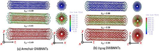
Figure 10. Snapshots of DWBNNTs under in-plane biaxial tension.
Download figure:
Standard image High-resolution image
Figure 11. Deformation mechanisms of (a) armchair, (b) zigzag and (c) a cross-section of the outer layer of DWBNNTs under in-plane biaxial tension loading. Color coding indicates the atomic stresses induced in the tubes.
Download figure:
Standard image High-resolution imageFurthermore, the in-plane shear load was applied to MWBNNTs (see figure 3(d)). During the deformation, the circular cross-section of MWBNNT deforms into an elliptical form, and the bonds get aligned to major and minor axes, which bear the maximum tension and compression stresses, respectively. Figure 12 shows the change in PE during the deformation of MWBNNTs under in-plane shear. The same pattern was observed in the case of in-plane biaxial tension loading (figure 9). Moreover, in this case the failure of tubes also occurs in two stages. This is again attributed to the fact that the inner tube fails first followed by the outer layer, as shown in figure 13. This figure clearly reveals that all layers of MWBNNT deform into elliptical shape, and the loads get transferred to inner layers via vdW forces. During the in-plane shear loading, circumferential stress is a function of both tensile and compression stress components shared by each bond of the hexagonal ring of DWBNNT, which is well explained in figure 14. It can be observed from figure 14 that the maximum load-bearing bonds are a2 and b1 in armchair and zigzag DWBNNT, respectively. A zigzag MWBNNT fails well before that of an armchair tube because the high stress-bearing bonds per hexagonal ring are four in the case of zigzag and two in the case of armchair MWBNNTs. The interlayer shear stress at the major and minor axes are zero due to the pure tension and compression loads applied across these axes, respectively. This can be observed from figure 13, which clearly depicts that the failure occurs at the major and minor axes. For the sake of brevity, the step-by-step failure of TWBNNTs and FWBNNTs under in-plane shear are provided in the supplementary figures S5 and S6. It was observed that the failure strain decreases with the increase in number of tube layers. For the sake of clarity, the deformation process of MWBNNTs under four loading conditions is provided as supplementary information video S2.
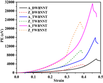
Figure 12. Variation of PE of MWBNNTs under in-plane shear loading.
Download figure:
Standard image High-resolution image
Figure 13. Snapshots of deformation of DWBNNTs under in-plane shear loading.
Download figure:
Standard image High-resolution image
Figure 14. Deformation mechanisms of (a) armchair, (b) zigzag and (c) a cross-section of outer layer of DWBNNT under in-plane shear loading. Color coding indicates the atomic stresses induced in the tubes.
Download figure:
Standard image High-resolution image3.2. Effect of temperature
To examine the effect of temperature on the elastic and failure behavior of MWBNNTs, we again used four loading conditions considering six different temperature steps: 0, 300, 500, 700, 900 and 1100 K. The temperature was increased from 0 to 1100 K by keeping the constant strain rate. The failure behavior of armchair and zigzag MWBNNTs subjected to uniaxial, twisting and in-plane biaxial loadings is shown in figures 15, 16 and 17, respectively. It can be observed from figure 15 that the trend of stress–strain behavior of DWBNNT, TWBNNT and FWBNNT is almost similar. The failure behavior of MWBNNTs subjected to in-plane biaxial and shear loadings for varied temperature was found to be the same as that demonstrated in figures 9 and 12, and for the sake of brevity, the plots are not shown here.
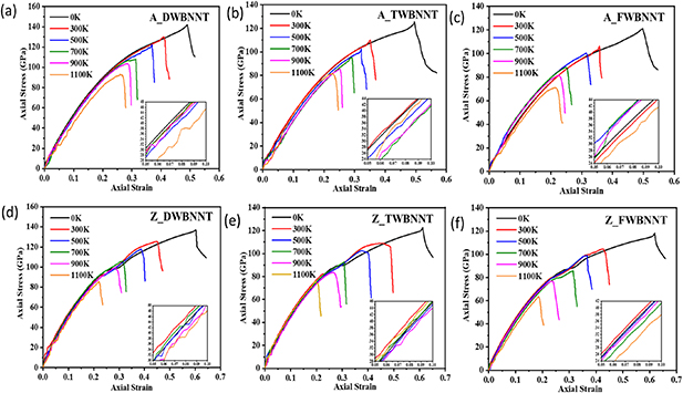
Figure 15. Stress–strain curves of armchair and zigzag MWBNNTs under uniaxial loading at varied temperatures.
Download figure:
Standard image High-resolution image
Figure 16. Variation of PEs of tubes under twisting at varied temperatures: (a) armchair and (b) zigzag DWBNNTs.
Download figure:
Standard image High-resolution image
Figure 17. Variation of PEs of tubes under in-plane biaxial loading at varied temperatures: (a) armchair and (b) zigzag DWBNNTs.
Download figure:
Standard image High-resolution imageIt may be observed from figures 15–17 that the temperature profoundly changes the mechanical behavior, especially the failure behavior of armchair and zigzag MWBNNTs. However, no apparent plastic deformation was observed, and thus brittle fracture persists in all cases considered herein. During the deformation under thermal loading, most of the energy is converted into kinetic energy and therefore, this results in the decrease in the stored strain energy, which eventually decreases the failure strain as the temperature increases. At higher temperature, the early formation of cracks occurs. This is due to the creation of topological defects after a critical strain value [70]. The formation of crack depends on the strain and thermal energies of MWBNNTs during the loading. The thermal energy of MWBNNTs increases with the temperature due to the thermal vibration of atoms; thus, the strain energy required for the failure reduces. As a result, the failure strength and strain of MWBNNTs are significantly reduced at a higher temperature irrespective of the type of loading condition.
Figure 15 shows the stress–strain curves of armchair and zigzag MWBNNTs under tension at different temperatures. The stress values at failure strain are considered as tensile strengths of MWBNNTs where the stress–strain curves dramatically drop. The failure strengths of armchair and zigzag DWBNNTs are 147 and 137 GPa, respectively, at 0 K, and these values decrease significantly as the temperature and number of tube layers increase. For instance, the failure strength of armchair and zigzag FWBNNTs is 121.1 and 118.2 GPa, respectively. As the temperature increases, the failure strength of armchair and zigzag DWBNNTs decreases significantly to 93.2 and 85.8 GPa, respectively, at 1100 K. However, armchair MWBNNTs are stronger than zigzag tubes, even at higher temperature. It can be observed from figures 16 and 17 that the temperature significantly reduces the PE of MWBNNTs. The effect of temperature is not similar in both armchair and zigzag MWBNNTs under twisting. The PE of zigzag MWBNNTs under twisting decreases substantially compared to armchair tubes. This finding shows that the armchair MWBNNTs have higher twisting resistance than that of zigzag tubes at a higher temperature. The same is true in the case of MWBNNTs under in-plane biaxial loading, as shown in figure 17.
The expressions previously derived herein were used to determine the values of E1, ν12, G12, K23 and G23 of MWBNNTs at varied temperatures, as shown in figure 18. The elastic coefficients of MWBNNTs decrease as their number of layers increases. This is due to the influence of included angles of B–N bonds of adjacent BN tube layers via vdW interactions and the failure initiation starts from the innermost tube layer. It can also be observed from figures 15–17 that the failure strength of MWBNNT decreases as its number of layers increases due to the occurrence of slippage between the two adjacent tube layers at finite temperature. The interlayer distance between the two adjacent layers slightly increases with the number of layers [12] and this results in the increase in inter-layer slippage, which eventually decreases the failure strength of MWBNNT. This is again attributed to the influence of included angles of B–N bonds of adjacent BN tube layers via vdW interactions [48]. It can be observed from figure 18(c) that the value of G12 decreases profoundly compared to all other elastic coefficients as the number of tube layers increases. For instance, the values of G12 of zigzag TWBNNT and FWBNNT are reduced by 28% and 37%, respectively, while the respective reductions in the case of armchair TWBNNT and FWBNNT are found to be 20% and 30% compared to zigzag and armchair DWBNNTs. All other constants of armchair and zigzag MWBNNTS are reduced by 4%–8 % and 8%–17%, respectively. As shown in figure 18, the elastic properties decrease with increase in temperature. As the temperature rises, MWBNNTs become softer and less stiff. Moreover, as the temperature increases, the kinetic energy of atoms in the tube increases and they start moving faster, which eventually reduces its strength. The effect of temperature on the elastic properties of armchair and zigzag MWBNNTs is almost similar. Even though the loading was uniformly applied over the whole MWBNNT, the atomic stresses were not uniformly induced, and this is attributed to the thermal fluctuations of atoms at higher temperature (shown in supplementary video S3). The total kinetic energy of MWBNNTs increases with the temperature. Due to the action of forces generated by thermal loading, the B and N atoms move from their original equilibrium positions, resulting in a soft and less rigid-like structure. At higher temperature, this temperature-stimulated softening is attributed to the higher thermal vibrations of B and N atoms. Such thermal vibration of B and N atoms makes MWBNNTs less stiff and due to the thermal agitation, the B–N bonds are more likely to reach the critical bond length and therefore, they break. The temperature-dependent elastic properties of MWBNNTs shown in figure 18 can be described by a simple linear equation as follows:


Figure 18. Variation of elastic properties of MWBNNTs with different temperature: (a) E1, (b) ν12, (c) G12, (d) K23 and (e) G23.
Download figure:
Standard image High-resolution image
where MT is the elastic modulus of MWBNNT at a given finite temperature, α is a material and chirality-dependent constant and M0 is the elastic modulus of MWBNNT at 0 K.
The obtained constants are summarized in table 2. Compared with the failure strength and strain, the elastic properties are less sensitive to temperature. The elastic properties of armchair MWBNNTs are more sensitive to temperature than zigzag tubes. It can be observed from figure 18 that the effect of chirality and number of layers on the values of G12 of MWBNNTs at different temperatures is more pronounced than all other elastic coefficients. The reason behind this can be found in figure 7, which shows that the PE of MWBNNTs increases with the number of tube layers under twisting, but their strength decreases due to the vdW interactions between the layers. The reduction rate of shear modulus is 1.955 × 10⁻⁴ to 1.43 × 10⁻⁴ TPaK−1 for armchair and zigzag MWBNNTs, respectively, as the temperature rises from 0 to 1100 K. A similar effect of temperature on the values of K23 of MWBNNTs is observed, as shown in figure 18(e). Table 2 reveals that the temperature significantly affects the values of K23 of MWBNNTs and the reduction rate of K23 is found to be in the range of 0.23 × 10⁻⁴ to 0.18 × 10⁻⁴ TPaK−1.
Table 2. Temperature-dependent elastic properties of MWBNNTs.
| MWBNNT |  (TPa) (TPa) | α (TPaK−1) |  (TPa) (TPa) | α (TPaK−1) |  (TPa) (TPa) | α (TPaK−1) |  (TPa) (TPa) | α (TPaK−1) |  (TPa) (TPa) | α (TPaK−1) |
|---|---|---|---|---|---|---|---|---|---|---|
| Armchair MWBNNTs | ||||||||||
| DWBNNT | 1.345 | 3.13 × 10⁻⁴ | 0.167 | 0.21 × 10⁻⁴ | 0.641 | 1.95 × 10⁻⁴ | 0.168 | 0.23 × 10⁻⁴ | 0.09 | 0.23 × 10⁻⁴ |
| TWBNNT | 1.232 | 3.23 × 10⁻⁴ | 0.161 | 0.18 × 10⁻⁴ | 0.519 | 1.70 × 10⁻⁴ | 0.151 | 0.22 × 10⁻⁴ | 0.079 | 0.20 × 10⁻⁴ |
| FWBNNT | 1.094 | 2.86 × 10⁻⁴ | 0.154 | 0.17 × 10⁻⁴ | 0.452 | 1.49 × 10⁻⁴ | 0.141 | 0.18 × 10⁻⁴ | 0.075 | 0.20 × 10⁻⁴ |
| Zigzag MWBNNTs | ||||||||||
| DWBNNT | 1.392 | 2.57 × 10⁻⁴ | 0.17 | 0.21 × 10⁻⁴ | 0.588 | 1.76 × 10⁻⁴ | 0.174 | 0.22 × 10⁻⁴ | 0.094 | 0.22 × 10⁻⁴ |
| TWBNNT | 1.259 | 2.42 × 10⁻⁴ | 0.165 | 0.21 × 10⁻⁴ | 0.473 | 1.59 × 10⁻⁴ | 0.157 | 0.20 × 10⁻⁴ | 0.083 | 0.21 × 10⁻⁴ |
| FWBNNT | 1.162 | 2.57 × 10⁻⁴ | 0.158 | 0.18 × 10⁻⁴ | 0.416 | 1.43 × 10⁻⁴ | 0.148 | 0.20 × 10⁻⁴ | 0.078 | 0.21 × 10⁻⁴ |
4. Conclusion
The five independent transversely isotropic elastic constants of MWBNNTs under uniaxial tension, in-plane biaxial, twisting and in-plane shear loadings at different temperatures were determined using MD simulations with a three-body Tersoff potential force field. Moreover, the effects of chirality, number of layers and temperature on the elastic and failure behavior of MWBNNTs were examined in detail. The following main inferences are drawn from the current study:
- Elastic, strength and failure properties of MWBNNTs decrease as the number of layers increases. Except for in-plane shear modulus, zigzag MWBNNTs show slightly higher elastic properties than armchair tubes due to the different B–N bond deformation mechanisms.
- MWBNNTs become softer as the temperature increases. As the temperature increases from 0 to 1100 K, the elastic moduli of MWBNNTs decrease. The effect of temperature is found to be prominent in the case of Young's and longitudinal shear moduli of MWBNNTs.
- The failure of MWBNNT structure depends on its chirality due to the different arrangement of bonds, which leads to different failure mechanisms. In the case of in-plane biaxial tension and shear loadings, the failure of MWBNNTs occurs in two stages.
Acknowledgments
The authors gratefully acknowledge the financial support provided by the Indian Institute of Technology Indore and the Science Engineering Research Board (SERB), Department of Science and Technology, Government of India. S I K acknowledges the generous support of the SERB Early Career Research Award Grant (ECR/2017/001863).
Conflicts of interest
There are no conflicts to declare.