Abstract
A power-transformed-and-managed triboelectric nanogenerator (PTM-TENG) is invented that is intended to give regulated power output for driving electronics. The design is based on a synchronized mechanical agitation that not only drives the TENG but also switches the connections for the capacitors for lowering the output voltage and increasing the output charges. An energy preservation efficiency of >95% was demonstrated. The PTM-TENG not only detected the external mechanical triggering action but also generated enough power for sending out an infrared signal.
Export citation and abstract BibTeX RIS
1. Introduction
As wireless sensing, implanted medical devices, and low-power-consumption portable electronics experience a rapid increase, scavenging mechanical energy from the ambient environment as a sustainable power source for these applications has attracted intensive interest. So far, various approaches for harvesting ambient mechanical energy have been demonstrated based on piezoelectric [1–4], electromagnetic [5, 6], and electrostatic [7, 8] effects. Recently triboelectric nanogenerators (TENGs) were invented as a new and powerful approach to energy harvesting because they outperform some of the existing technologies for mechanical energy conversion [9–15]. With periodic contact and separation of the two triboelectric surfaces with opposite triboelectric charges, the potential difference of the metal electrodes attached to the above triboelectric surfaces varies periodically, driving the inductive charges back and forth between the two electrodes [13, 16]. Typically, the output of a TENG is an AC signal that responds to the frequency at which mechanical triggering is applied; thus the output is required to be converted from AC to DC and stored before driving conventional electronics. More important, the output of a TENG has the common characteristic of high voltage but low current and total transported charges [17]. Therefore, it needs transformation before being applied to drive conventional electronics. But such a power-transformed-and-managed method is different from the traditional method of using a transformer for a sinusoidal-type AC signal because the output of a TENG can be a short pulse at variable frequency.
In this paper, we developed a power-transformed-and-managed TENG (PTM-TENG) by integrating a contact-separation-mode TENG with an array of self-connection-switching capacitors that are connected in serial when being charged and then in parallel during discharging. It was found that the PTM-TENG's output voltage can be tunably decreased and its output current and charges per applied load (impact) increased. As a comparison, the time for charging a 10 μF capacitance to 5 V by conventional TENG was 380 s, whereas that using a PTM-TENG (eight-capacitor array) was only 47 s, which means that the output charges were enhanced 8 times. Moreover, it is reported that a conventional TENG's output voltage at the external load decreases with the lowering of the load resistance [10, 11, 17, 18] and the working frequency [10, 17], which means a decrease in the output energy at a smaller load resistance or a slower impact speed. However, the PTM-TENG appears to be independent of these two factors. As a result, when the load resistance was 10 kΩ and the external impact speed was 0.1 ms−1, the output energy was enhanced 2200 times by the PTM-TENG. Furthermore, the PTM-TENG's charging/discharging mode was changed from continuous to instantaneous by the array of capacitors, which can increase instantaneous output current and power tremendously [17]. Finally, the PTM-TENG was successfully applied in a wireless touch sensor. Without any power supply, the sensing node not only detected touch stimulation but also converted the mechanical energy caused by the stimulation to electric power for infrared communication.
2. Fabrications and working principle
The PTM-TENG consisted of two parts: the contact-separation-mode TENG and the array of self-connection-switching capacitors. The TENG was fabricated using thin films of 3 cm × 1.5 cm. The two triboelectric materials were polydimethylsiloxane (PDMS) and polyester (PET) due to the large difference in their capabilities to attract and retain electrons according to the triboelectric series [10]. The PDMS surface was initially patterned as pyramids (shown in figure 1(a)) with silicon (Si) molds [19], whereas the PET surface was flat. When the PDMS and the PET were brought into contact, electrons were injected from the PET into the PDMS, resulting in surface triboelectric charges. When a gap was created between the two, an electric potential difference was produced between the PET and the PDMS that drove electrons through external loads to compensate for the triboelectric charges; when the gap disappeared, the potential disappeared and the electrons flowed back.
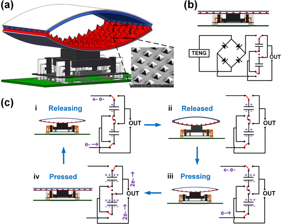
Figure 1. Schematic and working principle of the PTM-TENG: (a) 3D structure of the PTM-TENG. (b) The pressed PTM-TENG's cross-sectional view and the equivalent circuit diagram. (c) A full working cycle of the PTM-TENG.
Download figure:
Standard image High-resolution imageAn arch shape was introduced between the PDMS and the PET to assist in the contact and separation of the two films. Copper was used as the TENG's electrodes, which were placed on the back side of the PDMS and the PET. Immediately below the TENG was the array of self-connection-switching capacitors, which consisted of a capacitor array and a trigger. The capacitors were used as the energy storage unit. When the TENG began to drive electrons, the capacitors were connected in serial to be charged; when the TENG was fully pressed, the capacitors were connected in parallel to be discharged. The 'switch' for the connection of the capacitors was controlled by the trigger, which was automatically triggered by mechanical agitation to drive the TENG. Figures 1(a) and(b) show a schematic of the two-capacitor PTM-TENG. The equivalent circuit of the fully pressed PTM-TENG is illustrated in figure 1(b). As we can see, the capacitors were connected to the out circuit in parallel, which shows that the PTM-TENG was being discharged. Figure 1(c) illustrates the working principle of the PTM-TENG over one period. When the PTM-TENG began to be released (figure 1(c) i), two capacitors were immediately switched to be connected in serial and charged by the TENG with the use of a rectifier. Assuming a capacitance of C0 for each, the total capacitance was C0/2 when they were in serial connection and 2C0 when in parallel. After the PTM-TENG was released completely, a total of charges equal to Q01 were stored in two capacitors (figure 1(c) ii) that were still in serial connection. When the PTM-TENG began to be pressed, the two capacitors continued to be charged in serial. After it was fully pressed, a total of charges equal to Q02 were added into the capacitors (normally, Q01 = Q02). Subsequently, the underneath trigger was successively triggered, resulting in the two capacitors being disconnected from the TENG but reconnected in parallel with the external circuit again. That is one full work cycle of the PTM-TENG. As we can see, the total generated charges Q0 and voltage V0 in the serial capacitors Cs are expressed by
The charges Q1, Q2 and voltage V1, V2 in each capacitor are determined by
When the two parallel connected capacitors are discharged to the out circuit, the initial charges Qout and voltage Vout are as shown:
Therefore, with the two-capacitor array, the PTM-TENG's voltage can be tuned down to half, whereas the output charges can be doubled. Because the TENG has the advantage of high voltage output, the number of capacitors N can be increased further. Consequently, the output charges and voltage are described as follows:
By the same token, if the capacitors in the PTM-TENG are charged in parallel and discharged in serial, the output voltage is enhanced by the factor N.
3. Experiments
Based on the above-described principle, we have designed two-, four-, and eight-capacitor PTM-TENGs. The output performances of the conventional TENG and the PTM-TENG were compared. Figures 2(a)–(d) show the output voltages under different load resistances for a conventional TENG (called T0 for easy notation), a two-capacitor PTM-TENG (T2), four-capacitor PTM-TENG (T4), and eight-capacitor PTM-TENG (T8) (the Cs for T2, T4, and T8 were set around 250 pF).

Figure 2. (a)–(d) Vout of T0, T2, T4, and T8 under various load resistance.
Download figure:
Standard image High-resolution imageThe T0's voltage peaks (assumed as Vout ) showed obvious dependence on load resistance, whereas those of the PTM-TENGs were considerably more stable. It can be seen from the output curves that PTM-TENGs behave exactly as a discharging capacitor because they are indeed discharging based on capacitors. Particularly, when the load resistance is small, the discharging is very quick. Thus, non-simultaneous discharging of capacitors (caused by some mismatch in triggers) leads to several peaks. As the number N of the capacitors increased from 2 to 4 to 8, Vout decreased from 50 V to 30 V to 15 V (figure 3(a)). The T2's Vout were smaller than those of the T4's Vout by more than a factor of 2 because the two-capacitor array's output capacitance was so small that the discharging speed was too fast for the oscilloscope to obtain the exact peak value. Next, the total of output charges was calculated by

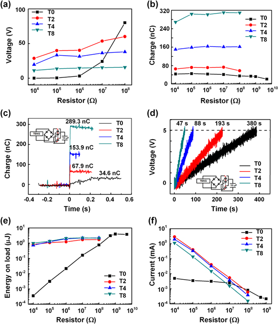
Figure 3. (a) Output voltages and (b) charges of the T0, T2, T4, and T8 under various load resistances. (c) Output charges after one mechanical impact. (d) Time-dependent plot of charging a 10 μF capacitor to 5 V. (e) Output energy (energy supplied to the load) and (f) current of the T0, T2, T4, and T8 under various load resistances.
Download figure:
Standard image High-resolution imageThe results are plotted in figure 3(b). It can be seen that the T0 transferred charges of about 40 nC in one cycle, whereas the T2, T4, and T8 increased this number by 1.8, 4.0, and 7.8 times, respectively, or 73 nC, 161 nC, and 310 nC. These results indicate that when N is 24, the total of output charges will increase more than 20 times, and Vout will be around 5 V, suitable for charging batteries. A 10 μF capacitor was used to examine the charging performance of the PTM-TENGs (the testing circuit is inset in figure 3(c)). Under the same mechanical impact, the T8, T4, and T2 charged the 10 μF capacitor to 289.3 nC, 153.9 nC, and 67.9 nC, respectively, whereas the output charges for the T0 were 34.6 nC. As for the time required to charge a capacitor of 10 μF to 5 V under the same impact frequency, the T0 took 380 s and the T8 took only 47 s, less than one-eighth of the former.
The output energies Eout are calculated as follows:

and they are compared in figure 3(e). It was found that the T0's Eout descended gradually as the load resistance decreased from 5 GΩ to 10 kΩ and dropped to nearly zero when the load resistance was less than 1 MΩ. Because the TENG behaves like a power source with large inner resistance, the load should be high enough to match the inner resistance and then get high output energy [10, 12]. As for the PTM-TENGs, with varying load resistance the Eout remained at the same level. This is because the output energy was dominated by the amount of charges stored in the capacitor array, which was supposed to be independent of load resistance. As a comparison, when the load resistance was 10 kΩ, the PTM-TENG's output energy Eout (e.g., for the T8) was about 2200 times higher than that of the T0. This indicates that when the load resistance decreases further, this difference may greatly increase. Subsequently, we fixed the load resistance at 1 MΩ and changed the external impact speed (controlled by a linear motor).
It can be seen from figure 4(a) that, the T0's Vout decreased when the impact speed decreased from 0.5 ms−1 to 0.01 ms−1 and dropped to almost zero when the impact speed was 0.01 ms−1, whereas the PTM-TENGs' Vout varied little as the impact speed was changed (more details about the output voltage can be found in figure S1, available at stacks.iop.org/NANO/25/225402/mmedia); this means that the Vout of a PTM-TENG is independent of impact speed because the total charges stored in the capacitor array are independent of the impact speed. Because the Eout of a PTM-TENG is also related to charge, it was found to be relatively stable even as the impact speed was varied for all three kinds of PTM-TENGs (figure 4(c)). In conclusion, a PTM-TENG's output energy is almost independent of impact speed, which increases its everyday usefulness. In addition, the output charges were also examined and compared in figure 4(b). The T8 output 8 times more charges than the T0, consistent with the above principle and experimental results.
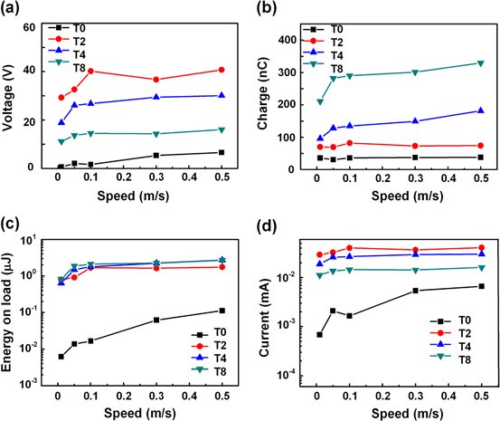
Figure 4. (a)–(d) Output voltage, charges, energy, and current of the T0, T2, T4 and T8 under various impact speeds.
Download figure:
Standard image High-resolution imageFurthermore, the output power of the T0 and the PTM-TENG were compared in figure 5. Because the PTM-TENG's charging/discharging mode was changed from continuous to instantaneous, the instantaneous output current and power could be increased tremendously [17]. When the load resistance is decreased further, it can be assumed that the instantaneous output current and power will be increased dramatically. Figure 3(f) and 5(a) show that when the load resistance was 10 kΩ, the T2's output current and power were respectively 580 and 340 000 times higher than those of the T0. Therefore, a PTM-TENG will be useful for some intermittent and low-power-consumption electronics. In this work, a PTM-TENG was used to fabricate a self-powered wireless touch sensor. When the PTM-TENG was pressed, it detected the action and meanwhile powered up an infrared emitter and sent out an infrared signal without any power supply. Placed on the other side was an infrared receiver. After the infrared signal was received, previously set actions could be executed (see supplementary data for video S1, S2). Additionally, the farthest transmitting distance was found to be 3 meters.

Figure 5. Output powers of the T0 and T2 under (a) various load resistances and (b) various impact speeds.
Download figure:
Standard image High-resolution imageFinally, because the PTM-TENG's output was transformed in order to decrease the output voltage and increase the output charges, the energy transform efficiency was investigated. As shown in figure 6(a), charges were initially stored in the capacitor array. Then the array was triggered to transform and discharge. Due to the mismatch of each capacitance, during the transformation electrons might have flowed inward, leading to some energy loss. Hence, the direct energy output without transformation and the output with transformation are compared in figure 6(b). It can be found that energy loss existed, but not a great deal. The T2, T4, and T8 all show energy preservation efficiency above 95%.

Figure 6. (a) Testing circuit diagram. (b) Non-transformed and transformed energy output. (c) Transform efficiency.
Download figure:
Standard image High-resolution image
4. Conclusions
In summary, we have developed the first power-transformed-and-managed triboelectric nanogenerator (PTM-TENG). Three improvements are demonstrated. The PTM-TENG's high output voltage is lowered, and the total transferred charges are increased; the PTM-TENG's output energy becomes independent of the load resistance and the mechanical impact speed; the PTM-TENG's peak output current and power are significantly enhanced owing to the instantaneous discharging mode, which is useful for some intermittent and low-power-consumption practical applications. An energy preservation efficiency of >95% has been demonstrated. Furthermore, a self-powered wireless TENG touch sensor was fabricated. The PTM-TENG not only detected the external mechanical triggering action but also generated enough power for sending out an infrared signal, which will be quite useful in future self-powered wireless sensing networks. In addition, it can be assumed that, if the PTM-TENG is charged in parallel and discharged in serial, the number of transferred charges should be reduced, but the voltage could be increased, which might be employed as a means of ignition in the future.
Acknowledgments
Thanks for the support from the 'thousands talents' program for pioneer researchers and its innovation team, China, and the Beijing City Committee of science and technology projects (Z131100006013004, Z131100006013005).