
Abstract
Using density functional theory (DFT), we report the modulated electronic and magnetic properties of MoS2 nanoribbon by passivating the ribbon edges with H and C separately. For the modeled symmetric MoS2 nanoribbon with a zig-zag type edge, one side is terminated at Mo and the other side is terminated at S. For the zig-zag type, we have studied two ribbons of width ∼3 Å and 6 Å respectively. Both of these pristine zig-zag type nanoribbons are found to be metallic and also ferromagnetic. However, the increase in the ribbon width results in a decrease in the net magnetic moment of the nanoribbon. Thereafter, we study the modulated electronic and magnetic properties of the nanoribbon of ∼3 Å width by saturating the ribbon edges with H and C. In one case, by passivating the zig-zag type ribbon with H at the S terminated edge, we find a net increase in magnetic moment of the ribbon when compared with the pristine one. Furthermore, when the ribbon is passivated with H at both of the edges, the net magnetic moment shows a decreasing trend. In another case, the zig-zag nanoribbon is passivated with C in a similar fashion to H and we find with one edge passivation the net magnetic moment of the ribbon decreases, whereas with both edges C passivated the ribbon magnetism increases significantly. However, the nanoribbon modeled with the armchair type of edge and terminated with Mo at both sides is found to be non-magnetic and semiconducting. Passivating the armchair type nanoribbon with H and C, we find the band gap shows an increasing trend when going from one side to both sides passivation. In all cases, the armchair type nanoribbons show non-magnetic behavior.
Export citation and abstract BibTeX RIS
1. Introduction
MoS2 belongs to the family of layered transition metal dichalcogenides (TMDCs), which are particularly interesting in the field of nanoelectronics and optoelectronics. A stable monolayer of MoS2 consists of one plane of Mo atoms sandwiched between two planes of S atoms where the Mo and S atoms are bonded with strong ionic–covalent bonds in a prismatic coordination. Although the S–Mo–S layers are tightly bound internally within the monolayer, the neighboring monolayers are stacked together by weakly interacting van der Waals forces [1]. Thus, a single layer of MoS2 (6.5 Å thick) can be extracted easily by using a simple scotch tape technique, like the way the graphane sheet is exfoliated [2, 3]. When it comes to the field of thin transparent semiconductors, MoS2 sheet can be considered as a complementary correspondent of graphane sheet [4]. However, the direct band gap of 1.8 eV [5] in the pristine MoS2 thin film makes it a superior potential candidate over graphane to replace silicon in the next generation of field effect transistors [6].
The successful fabrication of atomic layers of MoS2 in the form of nanosheets [7, 5, 8], nanotube [9] and even thin films [10, 11] has further triggered research interest in the rich electronic and magnetic properties. Although the mechanical and optical properties of MoS2 have been studied extensively, so far very limited effort has been directed towards the magnetic properties and band-gap engineering of the two dimensional (2D) and one dimensional (1D) MoS2 structures having different chirality. Room temperature ferromagnetism has experimentally been reported in a single crystal of MoS2 [12] and also in free standing MoS2 nanosheets [7]. However, complete understanding of the origin of magnetism, which is possibly due to the existence of a zig-zag type edge for the 2D MoS2 structure, has not yet been fully achieved.
In this aspect, using first principles calculations, MoS2 nanoribbons with zig-zag type edge are found to be metallic and ferromagnetic whereas the nanoribbons with armchair type edge are reported to be semiconducting and non-magnetic [13–15]. On the other hand, Botello et al have reported metallic behavior for the armchair type MoS2 nanoribbon, which further becomes semiconducting with H passivation [16]. However, tight binding DFT calculations by Seifert et al have reported a narrow direct band gap for the zig-zag type and a moderate non-zero band gap for the armchair type MoS2 nanotubes [17]. The first principles calculations by Pan et al have even reported the strain modulated electronic and magnetic properties of MoS2 nanoribbon [18]. In another scenario, by using first principles calculation Jiangang et al have reported modulated magnetic properties of MoS2 monolayer while chemisorbed with H, B, C, N, and O atoms [19].
For any technological applications in the direction of replacing graphene, it is crucial to study the edge dependent structural, electronic, and magnetic properties of 2D and 1D MoS2 in great detail. However to date, very few calculations have been reported on the edge dependent magnetic properties and band gap of 2D and 1D MoS2 nano structures. Predictions are even fewer when it comes to saturating the ribbon edges with other elements. Here, we explore a different aspect of modulating the electronic structure and magnetic properties of a MoS2 nanoribbon while passivating its edges with H and C atoms separately. In one case, we have a MoS2 nanoribbon terminated with a zig-zag type of edge (referred to as zz-MoS2-nR) and in another case we have the ribbon with armchair type edge termination (referred to as arm-MoS2-nR).
We find the zz-MoS2-nR is metallic and shows ferromagnetism. Furthermore, passivating the zz-MoS2-nR ribbon with H atoms at the Mo edge, we find an increase in magnetic moment whereas the H passivation at both edges leads to a decrease in magnetic moment. However, the zz-MoS2-nR passivated with C in a similar fashion results in an opposite trend. The one edge C passivation results in a decrease in magnetic moment whereas with two side C passivation the magnetism rather increases. The arm-MoS2-nR is found to be semiconducting and non-magnetic regardless of H or C passivation. The band gap of arm-MoS2-nR shows an increasing trend with both H and C passivation.
2. Computational methods
We have performed density functional theory (DFT) calculations by using the projector augmented wave (PAW) method as implemented within the VASP package [20–23] for calculating the structural, electronic, and magnetic properties of the MoS2 nanoribbons. The valence states of PAW potentials are 4p 5s 4d for Mo, s2 p4 for S, 1s for H and s2 p2 for C respectively. The exchange and correlation potential are approximated within generalized gradient approximation (GGA) by usingPerdew–Burke–Ernzerhof functional (PAW-PBE) [24] within VASP. The MoS2 nanoribbons are modeled by sandwiching one layer of Mo atoms in between two layers of S atoms as shown in figure 1. Here, we have modeled two types of nanoribbons depending upon how we terminate the 2D MoS2 sheet. In one case, we have a ribbon structure with a zig-zag type of edge (zz-MoS2-nR) of width ∼3 Å and have 15 atoms in the unit cell as shown in figure 1(a). For the symmetric zig-zag type structure, one edge is terminated at the Mo site and the other edge is at the S site as shown in figure 1(b). In the second case, we have an armchair type edge nanoribbon (arm-MoS2-nR) of width ∼3.1 Å having 30 atoms in the unit cell as shown in figure 1(c). Here, both edges of the ribbon are terminated at the S site as shown in figure 1(d). Furthermore, we saturate both types of nanoribbon edge with H and C separately. In the first scenario passivation is done at the (one) edge and then at both of the edges.
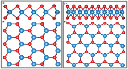
Figure 1. The side and top views of MoS2 nanoribbon, terminated with a zig-zag like end in figures (a) and (b), and with an armchair like end in figures (c) and (d). Blue: Mo; red: S.
Download figure:
Standard image High-resolution imageWe have maintained the periodicity of the ribbons along the conventional x-direction and vacuum spaces of 10 Å and 15 Å are maintained along the conventional y and z directions respectively to minimize the interaction between the periodic images of the ribbons. All the ribbon structures are fully relaxed while taking spin polarization into consideration. For the ground state configuration, we have taken the criterion for Hellmann–Feynman force to be less than 0.001 eV Å−1 for each atom in the ribbon. The self consistent energy convergence is taken to be 10−6 eV . For the plane wave basis set, the energy cut off is taken as a converged value of 500 eV. For the structure optimization, the Brillouin zone sampling was performed with a dense set of converged k-point grid (24 × 6 × 1) within the Monkhorst–Pack scheme [25] as implemented in VASP. The convergence of total energy with plane wave cut off and k-point mesh was chosen to be 10−3 eV . The Brillouin zone integrations are performed with a Gaussian smearing technique and the 24 × 6 × 1k-point grid is maintained for the bare as well as the H and C passivated MoS2 ribbon structures throughout the calculations. Since we have modeled our MoS2 nanoribbon with experimental lattice parameters, after getting a completely optimized structure we get a small pressure value of 0.098 GPa on the unit cell which is sufficiently small to be neglected.
3. Results and discussion
The results and discussion part is organized in the following manner. In the first section, we discuss the electronic and magnetic properties of the aforementioned zz-MoS2-nR, then with increasing the ribbon width. We have discussed the modulated electronic and magnetic properties of zz-MoS2-nR due to H passivation and C passivation separately in great detail. In the second section, we briefly discuss the electronic structure of H and C passivated arm-MoS2-nR. In the last section, we have summarized our results.
3.1. Zig-zag nanoribbon
We have the spin polarized optimized structure of pristine zz-MoS2-nR of width ∼3 Å as shown in figures 1(a) and (b). At both the ribbon edges, the Mo1–S(1/2) and Mo1–S(3/4) distances are found to be 2.39 and 2.41 Å and that of Mo5–S(9/10) is measured to be 2.37 Å. The pristine zz-MoS2-nR is found to be ferromagnetic and metallic. Our findings agree well with the previously reported results [15, 13, 14]. The cohesive energy per atom is estimated to be −6.97 eV. The net magnetic moment associated with the ribbon is found to be 1.108 μB. In specifics, the magnetic moments associated with the edge Mo atoms (Mo1, and Mo5 in figure 1) are found to be 0.076 and 0.704 μB respectively, whereas all other Mo atoms in the ribbon are found with nearly zero magnetic moment. The spin polarized partial densities of states (PDOS) for both the edge atoms, Mo1 and Mo5, are shown in figures 2(a) and (b). The net exchange splitting for the Mo1 d-electrons (figure 2(a)) is found to be negligibly small. For Mo5, the asymmetry between the majority and minority Mo d-states in figure 2(b) is quite noticeable and the net exchange splitting validates the finite magnetic moment of Mo5 in the ribbon structure. The Mo1 (figure 1(a)) hybridizes with the four nearest neighbor S, whereas Mo5 has only two nearest neighbor S. Thus, the Mo1 (d) electrons of are more delocalized compared to those of Mo5, resulting in a smaller magnetic moment for Mo1 compared to Mo5. Other than Mo5, a small contribution to the net magnetic moment also comes from the S atoms lying at the ribbon edge. The p-electrons of the S atoms (S1 and S2 figure 1(a)) lying at the edge of the zz-MoS2-nR are found to be spin polarized as shown in the PDOS plot in figure 2(a). Both the S atoms have a small magnetic moment of 0.176 μB whereas all the other S atoms in the ribbon remain with zero spin polarization.
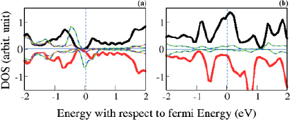
Figure 2. The black (majority spin) and red (minority spin) lines are the partial DOS plot of Mo1, and Mo5 in zz-MoS2-nR. In figure (a), the green, blue, orange and maroon lines are the PDOS of the four S atoms lying nearest to the Mo1 atom. In figure (b), the blue and green lines are the PDOS of the two S lying near to Mo5.
Download figure:
Standard image High-resolution imageTo understand the change in electronic and magnetic properties of the ribbon with width, we have also increased the ribbon width from ∼3 to ∼6 Å as shown in figure 3. The cohesive energy per atom is estimated to be −7.24 eV which is nearly 1 eV higher compared to the 3 Å width nanoribbon. The Mo atoms lying near to edge S atoms (Mo1 and Mo6 in figure 3) are of zero magnetic moment whereas the Mo atoms lying at the other edge of the ribbon (Mo5 and Mo10) have a magnetic moment of 0.15 μB on each. From the spin polarized PDOS plot, we see almost zero exchange splitting for Mo1 and Mo6 (figure 3(a)) and small exchange splitting for Mo5 and Mo10 (figure 3(a)). We find all other Mo atoms in the ribbon are of negligibly small magnetic moment and unlike 3 Å width nanoribbon, the edge S atoms are not spin polarized, as is also evident from PDOS plots. Thus, with increase in the ribbon width, the net magnetic moment of the ribbon shows a decreasing trend. A similar trend of decreasing magnetic moment with ribbon width has also been reported elsewhere [15].
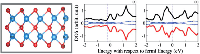
Figure 3. Left panel: MoS2 nanoribbon of width ∼6 Å. Right panel: spin polarized partial DOS. Black (majority spin) and red (minority spin) lines are the partial DOS plots of Mo1 and Mo6 in in figure (a) and of Mo5 and Mo10 in figure (b). Blue lines are the PDOS of the S atoms in the wire.
Download figure:
Standard image High-resolution image3.1.1. Hydrogen passivated zig-zag nanoribbon
We have the spin polarized optimized structures of the zig-zag nanoribbons passivated with H atoms at one edge [referred to as H-zz-MoS2-nR] and at both edges [referred to as H-zz-MoS2-nR-H] as shown in figures 4(a) and (b). We see a huge structural reconstruction for the ribbon, and mostly at the edge of the ribbon, due to H passivation. In H-zz-MoS2-nR, the Mo1–S(1/2) and Mo1–S(3/4) distances are found to be increased from 2.39 to 2.48 Å and 2.41 to 3.95 Å when compared with the bare zig-zag nanoribbon, and Mo5–S(9/10) remains unaltered. However, when compared with H-zz-MoS2-nR structures, there is no significant structural reconstruction in the case of H-zz-MoS2-nR-H ribbon structures.

Figure 4. Figures (a) and (a') present the side and top views of MoS2 in H-zz-MoS2-nR configuration. Figures (b) and (b') present the MoS2 H-zz-MoS2-nR-H configuration. Blue: Mo; red: S; green: H.
Download figure:
Standard image High-resolution imageIn both the cases the ribbons remain metallic (figure 5). The cohesive energies per atom of H-zz-MoS2-nR and of H-zz-MoS2-nR-H are estimated to be −6.57 eV and −6.27 eV respectively, which is found to be smaller than that of pristine zz-MoS2-nR. The stability of a S terminated MoS2 zig-zag nanoribbon is increased regardless of H passivation, as has also been reported elsewhere [13]. For H-zz-MoS2-nR, the net magnetic moment is found to be 1.55 μB, which is higher compared to that of pristine ribbon, whereas for H-zz-MoS2-nR-H the net magnetic moment is 0.952 μB, which is smaller compared to that of the pristine ribbon (table 1). With H passivation, the spin polarized S atoms (lying in the vicinity of Mo1 and Mo5) of the pristine ribbon are found to be of zero spin polarization. The contribution to the enhanced magnetic moment is found to be mostly coming from the Mo1 dangling with an H atom (figure 4(a)) and also from the Mo5 (table 1). After H passivation, the magnetic moment of both Mo1 and Mo5 are found to be increased by 0.5 and 0.1 μB (table 1) respectively. For all the other Mo atoms in the ribbon, the magnetic moment remains unaltered with H passivation. Comparing the spin polarized PDOS of Mo1 in figure 5(a) with that in figure 2(a) we find there is a substantial gain in net exchange splitting for the Mo1 atom due to H passivation. The Mo1 d-electrons get strongly spin polarized at the Fermi level. We find the presence of the H atom makes the Mo1–S bonding rather weaker due to the Mo–H bonding. The Mo1–S3 and Mo1–S4 bond distances in H-zz-MoS2-nR are found to be increased significantly by 1.54 Å compared to that in the pristine zz-MoS2-nR. Thus, the Mo1 d-electrons get more localized, resulting in an enhanced magnetic moment.
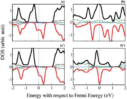
Figure 5. The black (majority spin) and red (minority spin) lines are the partial DOS of Mo1 in (a) and (a'), and that of Mo5 in (b) and (b') in H-zz-MoS2-nR and H-zz-MoS2-nR-H structures respectively. In (a) and (a'), the green, blue, orange and maroon lines are the PDOS of the four S nearest to the Mo1 atom. In (b) and (b'), the blue and green lines are the PDOS of the two S nearest to Mo5.
Download figure:
Standard image High-resolution imageTable 1. The charge and magnetic moment associated with individual elements in the zig-zag ribbon structures. Notations for different ribbon structures are; P: zz-MoS2-nR; 1H: H-zz-MoS2-nR; 2H: H-zz-MoS2-nR-H; 1C: C-zz-MoS2-nR; 2C: C-zz-MoS2-nR-C. The notation type E(x/y) represents Ex, Ey having the same magnetic moment or charge e. Here, E can be S, or H, or C and x, y are the numbers.
| Mo1 | Mo5 | S1/2 | S9/10 | H1/2 | H3/4 | C1/2 | C3/4 | |||||
|---|---|---|---|---|---|---|---|---|---|---|---|---|
| St. | μB | e | μB | e | μB | e | μB | e | e | e | e | e |
| P | −0.07 | 4.33 | 0.70 | 4.69 | −0.17 | 6.58 | −0.01 | 6.87 | — | — | — | — |
| 1H | 0.58 | 4.63 | 0.85 | 4.73 | −0.02 | 4.65 | −0.01 | 6.87 | 2.72 | — | — | — |
| 2H | 0.69 | 4.60 | 0.23 | 4.12 | −0.02 | 4.61 | 0 | 6.74 | 1.41 | 2.76 | — | — |
| 1C | 0 | 4.65 | 0.81 | 4.69 | 0 | 5.97 | −0.01 | 6.87 | — | — | 4.32 | — |
| 2C | 0.70 | 4.79 | 0 | 3.58 | −0.04 | 3.50/6.33 | 0 | 5.88/6.50 | — | — | 5.06/5.20 | 6.88/4.06 |
In the case of H-zz-MoS2-nR-H, we find the magnetic moment of Mo5 dangling with a H atom (figure 4(b)) rather shows a decreasing trend from 0.71 to 0.23 μB when compared with its pristine counterpart. The Mo1 has a net magnetic moment of 0.69 μB (table 1). The S atoms near the vicinity of both Mo1 and Mo5 remain with zero spin polarization which is also evident from the PDOS plots as shown in figures 5(a') and (b'). Comparing the spin polarized PDOS plot of Mo5 in H-zz-MoS2-nR-H (figure 5(b')) with that in H-zz-MoS2-nR (figure 5(b)) and in the pristine zz-MoS2-nR (figure 2(b)), we see a loss of d-electron density for Mo d-electrons which suggests a charge transfer from the Mo5 d-states to the neighboring elements. Furthermore, the net exchange splitting for the Mo5 atom decreases in H-zz-MoS2-nR-H when compared with the one edge passivated and pristine zig-zag ribbon structures. A similar trend of change in the magnetic moment has also been reported elsewhere [13]. In H-zz-MoS2-nR-H, the H–Mo5 hybridization leads to delocalization of the d-electrons which further supports the quenching of the Mo5 magnetic moment.
3.1.1.1. Charge transfer due to hydrogen passivation. To understand the unusual change in the magnetic properties of the ribbon in the presence of the H atoms, we have carefully analyzed the charge transfer occurring within the system with the help of Bader charge analysis, compared with our PDOS plots. Comparing the charge accumulation, we find in H-zz-MoS2-nR both the S atoms lying in the vicinity of Mo1 lose a substantial amount of charge of 1.9e unit each, whereas the Mo1 gains only 0.3e unit (table 1) and the H atoms are highly electronegative with a charge of 2.7e unit on each. The PDOS plots of Mo1 from figures 2(a) and 5(a) also suggest a significant amount of electron transfer to the Mo1 majority states near the Fermi surface, which is possibly from the neighboring S atoms as evident from the charge density plot in figure 6(a). The result is a net gain in magnetic moment for the H-zz- MoS2-nR structure. In the case of H-zz-MoS2-nR-H, the charge gain for the Mo1 remains similar to that of the H-zz-MoS2-nR, but for the Mo5 we see rather a significant 0.56e unit of loss of the charge (table 1). The charge on the S atoms lying close to Mo5 remains unaltered and the H atoms dangling to Mo5 have 1.4e unit of charge on each. Comparing the PDOS plot of Mo5 from figures 2(b), 5(b) and (b'), we see the electrons are getting transferred from Mo5 minority states to the neighboring H atoms, which results in a decrease in the net exchange splitting for Mo5. There are empty states for the minority Mo5 d-electrons near the Fermi energy, which we see from the charge density plot shown in figure 6(b).
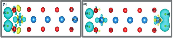
Figure 6. The net charge accumulation in H-zz-MoS2-nR compared to zz-MoS2-nR and that in H-zz-MoS2-nR-H compared to zz-MoS2-nR are presented in (a) and (b) respectively. Blue: accumulation of electron; yellow: loss of electron.
Download figure:
Standard image High-resolution imageTo understand the coverage effect with H passivation, we have removed one H atom from both H-zz-MoS2-nR and H-zz-MoS2-nR-H ribbons. Now we have passivated the ribbon edge with only one H atom (referred to as half-H-zz-MoS2-nR), and in the 2nd scenario both the ribbon edges are passivated with one H atom on each side (referred to as half-H-zz-MoS2-nR-H) as shown in figures 7(a) and (b). The cohesive energy per atom of half-H-zz-MoS2-nR and half-H-zz-MoS2-nR-H ribbons is estimated to be −6.7 eV and −6.9 eV respectively. In half-H-zz-MoS2-nR, the Mo1 dangling with a H atom has zero magnetic moment, and the Mo5 has a magnetic moment of 0.8 μB. All other Mo atoms are of negligibly small magnetic moment and the S atoms are of zero spin polarization. On the other hand, the half-H-zz-MoS2-nR-H ribbon is found to be of zero magnetic moment.

Figure 7. The side view of half-H-zz-MoS2-nR (a) and half-H-zz-MoS2-nR-H (b) nanoribbons. Blue: Mo; red: S; green: H.
Download figure:
Standard image High-resolution image3.1.2. Carbon passivated zig-zag nanoribbon
The spin polarized optimized structures of the zig-zag nanoribbons passivated with C atoms at one edge (referred to as C-zz-MoS2-nR) and at both the edges (referred to as C-zz-MoS2-nR-C) are shown in figures 8(a) and (b) respectively. The density of states plots in figure 9 reveal that in both cases the ribbons remain metallic. The cohesive energies per atom for C-zz-MoS2-nR and of C-zz-MoS2-nR-C are found to be −6.99 eV and −6.7 eV respectively. The C passivated zig-zag ribbons are found to be more stable compared to the H passivated zig-zag ribbons. Unlike H passivation, the ribbon structure does not change much with one edge C passivation. In C-zz-MoS2-nR, the Mo1–S(1/2) distances are found to be increased from 2.39 to 2.47 Å where as those of Mo1–S(3/4) and Mo5–S(9/10) remain unaltered when compared with the bare zig-zag nanoribbon.
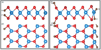
Figure 8. (a) and (a') present the side and top views of C-zz-MoS2-nR. (b) and (b') present those of C-zz-MoS2-nR-C structure. Blue: Mo; red: S; dark brown: C.
Download figure:
Standard image High-resolution image
Figure 9. The black (majority spin) and red (minority spin) lines are the partial DOS of Mo1 (figures (a) and (a')), and Mo5 (figures (b) and (b')) in C-zz-MoS2-nR and C-zz-MoS2-nR-C respectively. In (a) and (a'), the green, blue, orange and maroon lines are the PDOS of the four S atoms nearest to the Mo1 atom. In (b) and (b'), the blue and green lines are the PDOS of the two S nearest to Mo5. The dark magenta lines are the PDOS of the C atoms in the vicinity of Mo1 and Mo5.
Download figure:
Standard image High-resolution imageThe magnetic properties of the zig-zag nanoribbon with C passivation follow a reverse trend when compared with the H passivated ribbons. For C-zz-MoS2-nR, the net magnetic moment is calculated as 0.91 μB which is smaller compared to the pristine one, whereas for C-zz-MoS2-nR-C the net magnetic moment is 1.22 μB which is higher than that of the pristine zig-zag ribbon. In C-zz-MoS2-nR, the Mo1 dangling with the two C atoms (figure 9(a)) is of nearly zero spin polarization whereas the magnetic moment of Mo5 is increased by 0.1 μB when compared with the pristine ribbon (table 1). The spin polarized PDOS shows zero net exchange splitting for Mo1 (figure 9(a)), whereas Mo5 has a finite net exchange splitting (figure 9(b)). However, the zig-zag nanoribbon, passivated with C atom at both edges, undergoes a huge structural distortion compared to the one edge C passivated ribbon as shown in figure 8(b). In C-zz-MoS2-nR-C, the Mo5–S(9/10) bond distance (2.37 Å in bare zig-zag) changes asymmetrically to 2.56 Å and 2.41 Å respectively whereas the Mo1–S(3/4) bond distance reduces from 2.41 to 2.38 Å when compared with the bare zig-zag ribbon structure.
The distorted C-zz-MoS2-nR-C structure brings a dramatic change in the electronic structure as well as in the magnetic properties of the ribbon structure. Now in C-zz-MoS2-nR-C, the Mo1 has a magnetic moment of 0.706 μB and the Mo5 has zero magnetic moment (table 1). Although the Mo1 has a zero net exchange splitting in C-zz-MoS2-nR (figure 9(a)), this ensures a significant exchange splitting in C-zz-MoS2-nR-C (figure 9(a')). We see a significant increase in the Mo1 d-electron density in the majority bands and a decrease in the p-electron density of S atoms near the Fermi energy (figure 9(a')), which gives the probability of charge transfer from p-states of S to the majority d-states of Mo1. At the same time, the Mo5 having a finite net exchange splitting (figure 9(b)) in the C-zz-MoS2-nR structure lands up with zero net exchange splitting (figure 9(b')) in the C-zz-MoS2-nR-C structure. Other than that, we find both the C atoms dangling to Mo1 are strongly spin polarized with a net magnetic moment of 0.29 μB on each, whereas the C atoms dangling to Mo5 are of zero spin polarization.
3.1.2.1. Charge transfer due to carbon passivation. We looked into the charge transfer happening due to C passivation with the help of Bader charge analysis and compared it with the corresponding PDOS plots. The differences in the charge density of C passivated ribbons with respect to the pristine ribbon are shown in figures 10(a) and (b). Comparing the charge accumulation in C-zz-MoS2-nR with the pristine zz-MoS2-nR, we find both the S atoms lying in the vicinity of Mo1 lose a substantial amount of 0.6e unit charge and there is a gain in Mo1 by 0.3e unit. From the PDOS plots, figures 9(a) and (a'), one can see that the p-electrons of S1 and S2 channel to the d-states of Mo1, resulting in zero spin polarization for p-electrons of S, and the transferred electrons get equally distributed to both majority and minority states of the Mo1 d-states. The difference in the charge densities of C-zz-MoS2-nR with respect to zz-MoS2-nR in figure 10(a) shows a charge accumulation on Mo1 and charge depletion on S1 and S2. Here, the C atoms dangling to Mo1 are found to be electronegative, having 4.5e charge on each but with zero spin polarization.
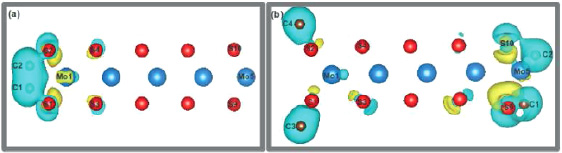
Figure 10. The net charge accumulation in C-zz-MoS2-nR compared to zz-MoS2-nR and that in C-zz-MoS2-nR-C compared to zz-MoS2-nR are presented in (a) and (b) respectively. Blue: accumulation of electron; yellow: loss of electron.
Download figure:
Standard image High-resolution image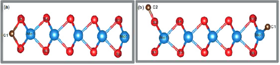
Figure 11. The side view of half-C-zz-MoS2-nR (a) and half-C-zz-MoS2-nR-C (b) nanoribbons. Blue: Mo; red: S; dark brown: C.
Download figure:
Standard image High-resolution image
In the case of the distorted C-zz-MoS2-nR-C structure, there is a charge gain of 0.4e for the Mo1 and a significant loss of 1.1e unit for Mo5 when compared with pristine ribbon. We find a substantial amount of charge is getting transferred from the p-states of S to the majority d-states of Mo1. From the PDOS plots of Mo1 in figures 2(a) and 9(a'), it is evident that there is a charge transfer from p-states of S1 and S2 to the majority d-states of Mo1. We have zero spin polarization for the p-electrons of S and a strong spin polarization for the d-electrons of Mo1. The difference in the charge densities of C-zz-MoS2-nR-C with respect to zz-MoS2-nR (figure 8(b)) shows a net charge accumulation on Mo1 and charge depletion on S1 and S2. The C atoms dangling to Mo5 are strongly electronegative having 6.1e unit of charge on each. Comparing the PDOS plots of Mo5 (figures 2(b) and 9(b')), and from Bader charge analysis, we find the Mo5 d-electrons get transferred from the minority states of Mo5 to the majority p-states of the C atoms. Thus, there is a quenching in Mo5 magnetic moment and the C atoms dangling to Mo5 also get strongly spin polarized.
To look into the coverage effect with C passivation, we have removed one C atom from C-zz-MoS2-nR and C-zz-MoS2-nR-C ribbons as shown in figures 11(a) and (b) and they are referred to as half-C-zz-MoS2-nR and half-C-zz-MoS2-nR-C respectively. The cohesive energy per atom of half-C-zz-MoS2-nR and half-C-zz-MoS2-nR-C ribbons is estimated to be −6.9 eV and −6.9 eV respectively. In half-C-zz-MoS2-nR, the Mo1 dangling with a C atom has zero magnetic moment, the edge Mo5 has a magnetic moment of 0.84 μB, and the S atoms are of zero spin polarization. On the other hand, the half-C-zz-MoS2-nR-C ribbon is found to have a magnetic moment of 0.74 μB. The Mo1 dangling with a C atom has a finite magnetic moment of 0.45 μB whereas Mo5 has zero magnetic moment. However, the C atoms dangling to Mo1 get strongly spin polarized with a net magnetic moment of 0.33 μB and the S atoms close to Mo1 also get small spin polarization, whereas both C and S atoms in the vicinity of Mo5 are of zero spin polarization.
3.2. Armchair nanoribbon
We have the spin polarized optimized structure of the armchair (arm-MoS2-nR) nanoribbon as shown in figure 1(b). The cohesive energy per atom of the arm-MoS2-nR is calculated to be −7.02 eV, which is a little higher compared to the zig-zag type ribbon. The ribbon is found to be non-magnetic and semiconducting. The estimated band gap is calculated to be 0.08 eV. At both ribbon edges, the Mo1–S(1/2) and Mo10–S(19/20) bond distances are found to be 2.39 Å and 2.4 Å respectively. The nanoribbon retains its non-magnetic properties with H passivation at one edge and at both edges. On the other hand, the band gap shows an increasing trend to 0.10 eV with one edge H passivation to 0.15 eV while passivating the ribbon with H at both the edges. A similar increasing effect in band gap with H passivation for armchair type MoS2 ribbon has also been reported elsewhere [13]. The Mo1–S(1/2) and Mo10–S(19/20) bond distances do not change much due to H or C passivation. The estimated cohesive energies for one edge and both edge H passivated ribbon are found to be 6.61 eV and 6.3 eV respectively. Passivating the ribbon with C in a similar fashion, we find the nanoribbons maintained their non-magnetic and semiconducting properties.
4. Summary
In summary, by using DFT calculations, we investigate the electronic and magnetic properties of MoS2 nano ribbons terminated with zig-zag and armchair type edges. For the zig-zag type, we have studied ribbons of width 3 Å and 6 Å respectively. Both ribbons with zig-zag type edge are found to be ferromagnetic as well as metallic. The contribution to the magnetic moment mostly comes from the edge Mo atoms. In contrast, the ribbon with armchair type edge is found to be non-magnetic and semiconducting with a band gap of 0.08 eV. Both the electronic structure and the magnetic properties of the ribbon structures are hugely modified by passivating the ribbon edges with H and C separately. The zig-zag type ribbon (width of 3 Å) passivated with two H atoms at one edge results in an increase and the passivation of four H atoms at both edges results in a decrease in magnetic moment. The one edge H passivation leads to a localization whereas the two edge passivation leads to a delocalization for the Mo d-electrons lying at the ribbon edges. However, with C passivation the magnetic moment changes in a reverse manner compared to H passivation. With C passivation, the zig-zag ribbon undergoes a huge structural distortion. With two side C passivation, there is a significant charge transfer from p-states of S to the majority d-states of the edge Mo atoms, which results in a significant increase in the ribbon net magnetic moment. For half coverage H passivation, there is a small increase in magnetic moment for one edge H passivation whereas both edge passivation results in zero magnetic moment. Similar effects are also observed for half coverage C passivation. For the armchair nanoribbons, though both the semiconducting and non-magnetic properties are maintained with H and C passivation, the band gap shows an increasing trend while going from one edge passivation to both edge passivation. For both types of edges, the nano scale ribbon structures are also found to be stable and the stability further increases with H and C passivation. These stable nano scale MoS2 ribbon structures whose functional properties can further be tuned by engineering their edge structures open up possibilities in future nano devices and spintronics applications.
Acknowledgments
Myskal Sagynbaeva is thankful to MARCO XXI-Erasmus Mundus in Central Asia for the PhD scholarship and Puspamitra Panigrahi would like to thank the Swedish Institute for the postdoctoral fellowship. We are also thankful to NSC, HPC2N and UPPMAX for providing us computing resources.