Abstract
This paper investigates the roles of semiconducting single-walled carbon nanotubes (SWNTs) and metallic SWNTs in the SWNT/poly(3-hexylthiophene) (P3HT)-based photovoltaic conversion system. SWNTs containing different fractions of semiconducting nanotubes were conjugated with P3HT by virtue of π–π interaction. The energy transfer and carrier transport mechanisms in the photovoltaic composites were experimentally investigated by optical absorption spectroscopy, photoluminescence spectroscopy and carrier mobility measurements. At low loading of SWNTs, a high percentage of semiconducting nanotubes result in diminished non-radiative decay of exciton and lower carrier mobility, causing higher open circuit voltage and lower photocurrent. At an optimized morphology, SWNT/P3HT/phenyl-C61-butyric acid methyl ester (PCBM) hybrid-based solar cells demonstrated much higher photocurrent than a reference solar cell (P3HT:PCBM) due to the improved carrier mobility. Further thermal annealing of the devices significantly increased the open circuit voltage to 610 mV, resulting in an 80% increase of power conversion efficiency in comparison to the reference solar cell. These results are expected to lay a foundation for the integration of various nanocrystals into solar cells for efficient photovoltaic conversion.
Export citation and abstract BibTeX RIS
1. Introduction
The polymer solar cell (PSC) is a potential substitute for the traditional silicon solar cell due to its advantages including low cost, eco-friendly low temperature solution fabrication, light weight and device flexibility [1]. However, low efficiency and a short lifetime still prohibit practical applications of the PSCs [2]. Currently, bulk heterojunction PSCs, consisting of an interpenetrating network of a conjugated polymer and fullerene derivative, as respective electron donor and acceptor materials, are receiving attention [3–5]. However, zero-dimensional phenyl-C61-butyric acid methyl ester (PCBM) shows low carrier mobility and optical absorption, resulting in limited photocurrent and open circuit voltage (Voc).
Generally, four successive processes govern the photocurrent generation: exciton generation, diffusion, separation and carrier collection. Thus, the photocurrent can be increased by optimizing each step, such as maximizing optical input [6–10], optical absorption [4, 5] and carrier transporting rate [13], as well as minimizing the exciton and carrier recombination rate [3]. Single-walled carbon nanotubes (SWNTs), which can be regarded as a rolled graphene sheet, have extraordinary electronic properties, such as high carrier mobility (μe = 108 cm2 V−1 s−1 for electrons and μh = 103 cm2 V−1 s−1 for holes) at 300 K [11], and huge current density capability (109 A cm−2) [12]. Integration of SWNTs into photovoltaic (PV) composites can increase photocurrent through facilitating exciton separation and carrier collection. SWNT-doped conjugated polymer may show higher hopping transport rate as a consequence of the increased density of carriers and Coulomb traps [13], resulting in higher carrier mobility in the polymer phase. In addition, π–π stacking between conjugated polymer and SWNTs induced a nanoscale alignment of conjugated polymer chains along the side-wall of the SWNTs [14, 15], resulting in a microcrystal structure of conjugated polymer along the SWNT [14]. Meanwhile, the increasing interface between conjugate polymer and SWNT can enhance the exciton separation and electron transfer. The absorption intensity of the polymer/SWNT composite can also be increased due to the electronic interaction between them [16]. Generally, the conjugated polymer chain can wrap SWNTs and thereafter uncoil the chain, resulting in longer conjugation length [17]. Therefore, the bandgap of the SWNT/polymer composite may be lower than that of the pure conjugated polymer for more efficient photovoltaic conversion.
For a mixture of metallic (m-) SWNT/semiconducting (s-) SWNT incorporated in a conjugated polymer/PCBM solar cell, however, it has been reported that the m-SWNT can be bimolecular recombination sites, thereby diminishing photocurrent and efficiency [18–22]. Density functional theory calculations show that only the s-SWNT can form an ideal type-II PV heterojunction (staggered energy gap offset junction), with poly (3-hexylthiophene) (P3HT) [19]. Their interface facilitated the exciton separation rather than providing recombination sites. Even if doping with a small amount of SWNTs can increase the photocurrent of conjugated polymer solar cells, the SWNT/conjugated polymer composite solar cells showed lower Voc [18, 23], resulting in low efficiency of solar cells. This may be caused by penetration of the SWNTs into the electrode, decreasing the shunt resistance of the device. Thus, although numerous of attempts have been made to investigate the carbon nanotube/conjugated polymer composite for photovoltaic devices, no experimental effort has been made to investigate the role of s-SWNT in the photovoltaic conversion for concurrently increasing both the photocurrent and Voc of SWNT/conjugated polymer solar cell. The mechanism of carrier generation and recombination at the s-SWNT/conjugated polymer interface remains to be understood.
In this paper, we investigate the photophysical properties of the SWNT/P3HT composite as a function of s-SWNT fractions. Atomic force microscopy (AFM), optical absorption spectroscopy, photoluminescence (PL) spectroscopy and carrier mobility measurements were employed for probing the roles of s-SWNT and m-SWNT in the solar cells. The efficiency of the resultant devices was tested and analyzed.
2. Experiment
2.1. Preparation of SWNT/P3HT hybrid composite
In order to retain pristine electronic characters, two grades of SWNT were used as received without any treatment. One grade is denoted SG-SWNT, containing >90% s-SWNT (SG 65, SouthWest NanoTechnologies, Inc.). The other grade, denoted normal (N-) SWNT, consisted of around 67% s-SWNTs [24]. In a typical process, 0.006wt% SWNT solution was first prepared by 2 h probe sonication (Misonix sonicator, model 3000) of 6 mg SWNT in 100 g 1,2-dichlorobenzene (oDCB 99% pure, Acros Organics). Regioregular poly(3-hexylthiophene) (rr-P3HT, 4002-E, Rieke Metals, Inc.) was magnetically stirred in oDCB for more than 24 h. Subsequently, to prepare different composite solutions with various SWNT concentrations, different weights of SWNT solutions, P3HT solutions and pure oDCB were mixed together under the bath sonication followed with long-time magnetic stirring. The SWNT loading percentage was defined as the weight ratio between SWNT and P3HT in the composite. The concentration of P3HT in oDCB was always set to 1 wt% in all samples.
2.2. Characterization of SWNT/P3HT composites
For atomic force microscopy (AFM, Veeco multimode) characterization, thin SWNT or SWNT/P3HT film was spin-coated on indium tin oxide (ITO) substrate. The optical absorption of solutions was characterized by UV–vis–NIR spectrometer (Model: Shimazu UV-3600). The photoluminescence (PL) measurements were carried out using laser excitation with 532 nm wavelength, dispersed using a 0.75 m spectrometer, and detected using a photomultiplier in photon counting mode. The carrier mobility measurement was based on a space-charged-limited current (SCLC) method.
2.3. Fabrication and characterization of SWNT integrated solar cells
The SWNT/P3HT composite-based photovoltaic device was fabricated according to the following architecture: ITO/ poly(3,4-ethylenedioxythiophene):poly(styrene sulfonate) (PEDOT:PSS)/SWNT:P3HT:PCBM/aluminum. Patterned ITO glass substrate (1 ± 2 Ω/sq surface resistivity, 84% optical transmittance at 550 nm, Thin Film Devices Inc.) was cleaned by detergent, distilled water, acetone and isopropyl alcohol for 10 min/step successively. The resulting structure was dried overnight in an oven maintained at 110 °C. PEDOT:PSS (CLEVIOS P VP AI 4083) was spin-coated in air at 3000 rpm for 30 s on a pre-cleaned ITO substrate, followed by thermal treatment on a hot plate at 140 °C for 30 min. To prepare the PV solution, the SWNT/P3HT composite solution was mixed with PCBM at a weight ratio of 1:1. All PV solutions have a total concentration of 2 wt% in oDCB. The PV solution was then stirred for more than 12 h and bath-sonicated ∼10 min prior to spin-coating on ITO/PEDOT:PSS substrate at 800 rpm for 1 min in a nitrogen-filled glovebox. Immediately following application of the PV layer, thermal annealing was performed at 10 min and 130 °C. Subsequently, 100 nm thick aluminum strips were thermally evaporated onto the PV layer. The resultant solar cells were created over an area of ∼0.08 cm2 according to the ITO and Al electrode confinement. The photovoltaic efficiency was tested under illumination of an AM1.5 spectrum simulator (16S 150, Solar Light Co.), and the illuminated voltage–current curves were recorded using a Keithley 2400 digital multi-source meter. Reference solar cells were prepared using the same procedures.
3. Results and discussion
3.1. Morphology of SWNT/P3HT composites
Typically, the high affinity between SWNTs readily leads to aggregation and renders them insoluble in a variety of solvents [25]. However, when sonicating SWNTs in oDCB, the sonopolymer generated from oDCB decomposition can debundle SWNTs and help to stabilize them in oDCB [26]. We find that the solution of SG-SWNT and N-SWNT in oDCB is exceptionally stable for at least three months. AFM images of materials spin-coated on ITO are shown figure 1. The SG-SWNT/oDCB solution (0.006 wt%) image in figure 1(a) illustrates the long SG-SWNTs observed. The length of SG-SWNTs is usually more than 500 nm while the average height (diameter) of SG-SWNTs is ∼3 nm, indicating most of the SWNTs are in the individual or small-bundle state.
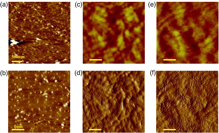
Figure 1. AFM images of (a) height of SG-SWNTs, (b) height image of P3HT/SG-SWNT 10 wt%, (c) and (d) correspond to height and amplitude image of P3HT/SG-SWNT 0.1 wt%, respectively. (e), (f) are height and amplitude image of P3HT film, respectively. Scale bars are 200 nm except as noted.
Download figure:
Standard imageWhen mixing the SWNTs and P3HT solution, the long chain of conjugated polymer P3HT can wrap on SWNTs, making the SWNT/P3HT hybrid composite soluble in organic solvents. At high SG-SWNT loading percentage (10 wt%), as shown in figure 1(b), the dominant feature is a long fiber network with the feature height ∼6 nm, suggesting a conjugate of P3HT on SG-SWNT. The complicated network may be caused by the high loading SG-SWNT percentage and crystallization of P3HT. On the other hand, at low SWNT loading concentration (0.1 wt%), it is difficult to get a clear fiber feature, as seen in figures 1(c) and (d). This may be due to the low SWNT concentration and miscibility of SWNT/P3HT [29]. In addition, the roughness of the SWNT/P3HT film was increased by 5%–8% in comparison to the pure P3HT reference film in figures 1(e) and (f).
3.2. Optical absorption of SWNT/P3HT composite
SWNTs and SWNT/P3HT were each dispersed in oDCB. Optical absorption results are shown in figure 2. Figure 2(a) shows a significant difference between SG-SWNT and N-SWNT spectra. The SG-SWNT shows a strong absorption peak at ∼1020 nm, indicating the enrichment of (7, 5) s-SWNT [27]. This signature peak also appeared when P3HT was doped with SG-SWNT at 0.1 wt% concentration, as shown in figure 2(b). The s-SWNT characteristic peak is due to van Hove singularities in its electronic structure [27] and is an indication of the good dispersion of SWNTs in P3HT.
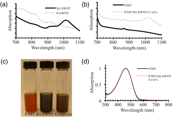
Figure 2. (a) Optical absorption of SG-SWNT and N-SWNT. (b) P3HT and SG-SWNT/P3HT composite absorption spectrum. (c) Optical photo of P3HT, SG-SWNT and P3HT/SG-SWNT composite solutions. (d) Optical absorption of P3HT and its composite with 0.1 wt% SG-SWNT loading concentration.
Download figure:
Standard imageWhen the SWNT solution was added to the P3HT solution under stirring, the solution changed color from orange to dark red, indicating stable dispersion and good miscibility of the components, as illustrated in figure 2(c). In addition, incorporation of SG-SWNT in P3HT produced the broad absorption band in figure 2(d). The absorption peak at ∼460 nm is contributed from the π–π* transition of P3HT conjugated segments [17]. The higher vibronic absorption at 580–620 nm of P3HT/SWNT composites originates from the increased interaction of electronic and nuclear motions of P3HT molecules due to the incorporation of SWNTs [28, 29]. The redshift of the composite absorption is an indication of enhanced P3HT crystallinity [22, 28], implying a lower bandgap than that of P3HT [17]. The SWNT may interact with P3HT and uncoil its chain, resulting in long conjugated length. The SWNT/P3HT composite-based photovoltaic material should subsequently have high photon absorption efficiency and commensurately high photocurrent.
3.3. Photoluminescence measurement
Weakly bound excitons, produced by optical excitation in the semiconducting polymer P3HT, can dissociate at the donor–acceptor interface or recombine either radiatively or non-radiatively [30]. Exciton decay at m-SWNT and larger diameter s-SWNT, as well as the exciton separation at small-diameter s-SWNT/P3HT and m-SWNT/P3HT interfaces, each diminish the PL intensity of the SWNT/P3HT composite [20, 22, 31]. We found the PL emission intensity decreased with the increasing percentage of SWNTs in the composites, as shown in figure 3. The more SWNTs were filled, the less radiative emission was exhibited. This systematic trend should stem from the energy transfer from P3HT to SWNT prior to exciton decay in P3HT, since the P3HT content is the same in all samples. In addition, the PL intensity of the P3HT/SG-SWNT 0.1 wt% composite was higher than that of the P3HT/N-SWNT 0.1 wt% composite. Since the 0.1 wt% SG-SWNT-doped sample contains a small amount of m-SWNT, the possibilities of non-radiative emission through exciton separation and recombination at the m-SWNTs/P3HT interface was reduced [20]. Hence, we postulate the m-SWNT/P3HT interface may boost exciton separation, resulting in reduced emission. The m-SWNT may also serve as deep trap sites in the exciton transition process, enabling non-radiative Shockley–Read–Hall recombination. In contrast, due to the formation of a type-II heterojunction [19], illustrated in figure 4, the s-SWNT/P3HT interface is not an energetically favored site for exciton recombination, making more excitons available for free charge generation. This suggests that the s-SWNT/P3HT interface is more suitable for constructing the D–A heterojunction, and their composite is more efficient for photovoltaic conversion.
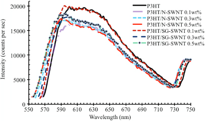
Figure 3. Photoluminescence of P3HT/N-SWNT and P3HT/SG-SWNT at 0%, 0.1, 0.3 and 0.5 wt% doping concentration.
Download figure:
Standard image
Figure 4. Illustration of energy level pinning between electron donor P3HT and (a) m-SWNT, (b) s-SWNT: a (7, 5) s-SWNT energy band structure is used.
Download figure:
Standard imageIn addition, a clear blueshift of the SWNT/P3HT composite PL peaks is observed. The shift of the PL peaks indicates the ground state energy transfer between P3HT and SWNTs [31, 32]. The ground state interaction may be due to overlapping of the P3HT and SWNT valence electrons. As indicated by That et al [33], the nanotubes may serve as deep electron traps in SWNT/P3HT composites. Electrons will fill these traps, producing a field near the nanotubes. This field will elevate the energy of the lowest exciton state, leading to the blueshift of the luminescence. A small shift indicates that fewer electrons were transferred from P3HT to SWNT. The shift direction of the peaks is also dependent on the loading concentration and dispersion quality. The blueshift of PL was only found at low loading of SWNTs in poly [2-methoxy-5-(2'-ethylhexyloxy)-1,4-phenylenevinylene] (MEH-PPV) rather than at high loading [31]. Thus, the blueshift is an indication of exciton separation at the SWNT/P3HT interface and low doping concentration. Furthermore, the significant difference in shift amplitude, as shown at the ∼560 and ∼730 nm wavelengths in figure 3, was found in the 0.3 wt% samples. The PL of N-SWNT/P3HT showed more shift than SG-SWNT/P3HT, an indication of more exciton separation or decay at the m-SWNT/P3HT interface.
3.4. Carrier mobility measurement
Hopping processes generally dominate carrier transport in disordered semiconducting polymers [34], and the effective carrier mobility is dependent on the density, depth and filling of hopping or trapping sites. The doping of disordered organic material increases the density of carriers and creates deep Coulomb traps. Thus, enhancement of carrier mobility in the SWNT-doped P3HT is expected, resulting in higher photocurrent. Here, we used a space-charge-limited current (SCLC) method to measure the carrier mobility of SWNT/P3HT composite films [35, 36]. A 100 nm thick composite film was placed between ITO and the aluminum electrode. In this configuration, the energy barrier between the work function of ITO ( − 4.7 eV) and the highest occupied molecular orbital (HOMO) of P3HT ( − 5.1 eV) is so small that the diode current is limited by space charges rather than injection. In addition, holes were the majority carriers in this measurement.
At a low driving voltage, the dark current density (J)–voltage (V) curve shows ohmic behavior [37]:

where q is the elementary charge, n0 is the free carrier density, μ is the carrier mobility and d is the thickness of the P3HT/SWNT film. At a higher applied voltage, the current becomes SCLC, which is governed by the Mott–Gurney equation [35]:

where ε = 4.1 is the relative dielectric constant of P3HT [23], ε0 is the free space permittivity and θ = 1 is the ratio of the number of free carriers to the total number of carriers. The log–log plot of J versus V, shown in the inset to figure 5, exhibits a two-slope dependence corresponding to the ohmic and SCLC regions. The turning point between these two behaviors, indicated by the arrow in the inset of figure 5, can be used to calculate the carrier mobility using equation (2); results are summarized in figure 5 for the different samples investigated here.
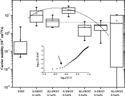
Figure 5. Carrier mobility SWNT/P3HT composite film with different loading concentration and type of SWNTs. Inset: plot of log10(J) versus log10(V), demonstrating the turn point (indicted by arrow) between ohmic contact and SCLC region.
Download figure:
Standard imageIn comparison with the pristine P3HT film, enhanced carrier mobility is observed for both N-SWNT- and SG-SWNT-doped P3HT composite films. This is attributed to the improved carrier transport of the nanotube network. The solid curve and dashed line in figure 5 illustrate the carrier mobility dependences for the N-SWNT and SG-SWNT composites, respectively. The carrier mobility of the N-SWNT-doped film has a peak value at 0.3 wt% doping level. The decrease at 0.5 wt% is attributed to the high carrier recombination rate at m-SWNT [18]. On the other hand, the carrier mobility in the SG-SWNT composite does not change much with loading concentration. At 0.5 wt% doping level, the SG-SWNT-doped sample has higher carrier mobility than N-SWNT composites. The possible reason is that blocking of the hole transfer from P3HT to s-SWNT, depicted in figure 4(b), makes the SG-SWNT function primarily based on electron transport. Slightly increasing the doping of SG-SWNT does not greatly change the hole majority-carrier mobility. In the N-SWNT composites with low doping level, both holes and electrons can efficiently transport in the m-SWNT network before recombination. In combination with the PL measurement, the carrier mobility results indicate that the m-SWNT/P3HT interface can assist exciton separation, making carriers available. In addition, m-SWNT also serves as bimolecular (non-radiative) recombination sites in carrier transportation, reducing the overall carrier mobility at the heavy doping composite.
3.5. SWNT/P3HT composite-based solar cell
Bulk heterojunction (BHJ) solar cells were fabricated by SWNT/P3HT/PCBM composites, and their J–V curves are shown in figure 6. Directly employing as-prepared SWNTs/P3HT:PCBM solutions in BHJ solar cells causes poorer efficiency because of the lower fill factor (FF), Voc and short circuit current (Jsc) in figure 6(a). With greater SWNT loading, lower device efficiency is observed. The decrease in Voc and FF was partly due to the reduction in shunt resistance as percolated conductive SWNT networks form in the PV film [28, 38, 39]. In addition, we postulate that the lower Jsc, Voc and FF were induced by poor morphology of the SWNT/P3HT/PCBM layer. The isolated SWNTs, which were not wrapped with P3HT, can easily aggregate and form bundles in the SWNT/P3HT:PCBM film. The existence of these bundles may break the continuity of the carrier transport network. The SWNT/P3HT composite film was found to show higher carrier mobility than that of the pure P3HT film (figure 5). Hence, we assume the evolution of three-phase SWNT/P3HT:PCBM morphology is different from the P3HT/SWNT bi-phase network. The PCBM may break the SWNT/P3HT interaction, resulting in poor morphology of three-phase composites.
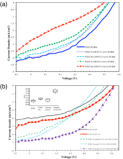
Figure 6. J–V curves of bulk heterojunction solar cells with different composites (a) without and (b) with passing the composite solution through 0.45 µm PTFE filters before coating. Inset of (b) shows the box plot of power conversion efficiency (PCE) with respect to donor material and post-annealing (PA).
Download figure:
Standard imageTo remove large SWNT bundles and SWNT/P3HT:PCBM clusters, 0.5 wt% SWNT/P3HT:PCBM solution was filtered through a polytetrafluoroethylene (PTFE) syringe filter (pore size:450 nm, Whatman Inc.). The filtered solution was nominally marked 0.5 wt% SWNT/P3HT composite solution; however, the actual concentration of SWNTs in the filtered solution should be much lower than 0.5 wt%. Because the pure SWNT has a length about 500 nm, we believe only the short P3HT/SWNT core shell hybrid structure can pass through the filters. The isolated SWNT was removed after filtering.
The solar cells with nominal 0.5 wt% SWNT/ P3HT composite as a donor material showed around a 50% increase of photocurrent, as demonstrated in figure 6(b). This result further confirms the increased carrier mobility and it was consistent with the measurement of carrier mobility. The Jph of the SG-SWNT/P3HT composite-based device was lower than that of the N-SWNT device and this is due to the lower carrier mobility of the SG-SWNT composite compared with the N-SWNT composite at low loading concentration, as demonstrated in figure 5. The Voc of both SG-SWNT and N-SWNT composite devices was reduced as a result of the decreased shunt resistance. However, the SG-SWNT device exhibited a higher Voc in comparison with the N-SWNT devices. This may be due to the type-II junction formation between P3HT/s-SWNT, as shown in figure 4. Upon 150 °C post-thermal annealing (PA) for 10 min in dry nitrogen, the Voc increased to 0.61 V for both P3HT and SWNT/P3HT composite-based devices.
The increase of the Voc should be attributed to the recovery of large shunt resistance as a result of the improved PV layer/electrode interface quality and the reduced leakage current [40]. In combination with the use of the SWNT composite and the annealing process, both Jsc and Voc were increased. The average efficiency of SWNT/P3HT/PCBM devices was ∼1.8% while the P3HT/PCBM devices showed an average efficiency of 1%, i.e. 80% increase as seen in the inset of figure 6(b). The increased rate of power conversion efficiency, resulting from the synergetic effect of incorporating SWNTs and annealing processing, is more significant than the enhancement rate in previous reports regarding carbon nanotube solar cells [41, 42].
4. Conclusion
In summary, we have found that the s-SWNT and m-SWNT played a different role in the SWNT-based organic solar cell. Compared with m-SWNT, the s-SWNT/P3HT composite not only demonstrated high carrier mobility, but also facilitated charge dissociation through the energetically favored exciton separation sites. Consequently, by removing large bundles of SWNTs in the SWNT/P3HT:PCBM solution, the SWNT/P3HT:PCBM solar cell showed higher photocurrent than the reference P3HT:PCBM device. The SG-SWNT/P3HT:PCBM solar cell showed higher open circuit voltage and lower photocurrent compared with the N-SWNT device, resulting from the low m-SWNT content in the SG-SWNT/P3HT hybrid which has lower non-radiative decay and carrier mobility. Finally, through employing thermal annealing of a completed device, the open circuit voltage of the N-SWNT device was further improved. In comparison with the reference device, an 80% increase of efficiency was achieved as a consequence of incorporating SWNTs and post-annealing. These results provide an understanding of optical and photonic interactions between SWNTs and conjugated polymers. The strategies derived from this work can be extended to other polymer solar cell system.
Acknowledgments
This work was funded by 3M Corporate (grant no. 5284547), and also partially supported by the National Science Foundation CAREER award (CMMI-0953674), the Air Force Office of Scientific Research (FA9550-10-1-0525) and the State of Texas Advanced Research Program. The authors also acknowledge Drs Brandon Weeks and Gengxin Zhang in the Department of Chemical Engineering, Texas Tech University, for helping with the thermal evaporation.