
Abstract
We show by the first-order perturbation theory and the configuration interaction method that the Coulomb interaction in quantum rings mixes electron–hole pair states with the same total angular momentum, which makes it difficult to observe a clear excitonic Aharonov–Bohm (A–B) effect. To avoid this situation, we propose the use of a combined structure of a quantum dot on the top of a quantum ring with an applied static electric field. Under moderate experimental conditions with respect to the applied electric and magnetic fields, we show that we can observe the excitonic A–B effect due to the reduction of the Coulomb interaction and an increase in the difference between the average radii of the electron and hole trajectories.
Export citation and abstract BibTeX RIS

Original content from this work may be used under the terms of the Creative Commons Attribution 3.0 licence. Any further distribution of this work must maintain attribution to the author(s) and the title of the work, journal citation and DOI.
1. Introduction
Since the first report on the self-assembly of semiconductor quantum rings in 1997 [1], ring-shaped nanostructures have been attracting extensive attention as they offer a new platform to investigate the Aharonov–Bohm (A–B) effect using spectroscopic techniques. The kinetic energy of an electron in a one-dimensional (1D) ring with an infinitesimally small width under a magnetic field (B) piercing the ring interior is expressed as [2]
where  is the effective mass, R is the ring radius,
  is the angular momentum that specifies the electron motion,
  is the magnetic flux,
  is the flux quantum, and e is the elementary charge. The spectral set
  becomes identical when
  , so it leads to a magneto oscillation in the energy spectrum with an oscillation period of
  . A signature of the A–B oscillation was observed using the far-infrared capacitance spectroscopy for self-assembled quantum rings [3].
Similar spectral oscillation is expected to appear in the recombination energy of an electron and a hole, which form an exciton. The ring size in this case must be smaller than the exciton Bohr radius. Otherwise, the bound electron and hole move together inside the ring, and the charge-neutral composite does not respond to the magnetic flux [4]. Thus, different trajectories for the electron and hole are needed for the emergence of the excitonic A–B effect [5]. For this purpose, the non-uniform confinement of the electron and hole along the growth direction was utilized by applying an electric field perpendicular to the ring to make the average radius of their trajectories different from each other [6, 7]. However, the oscillation signature in both the experimental and the theoretical results of this case was not significant, probably because the Coulomb potential mixed different electron–hole pair states so that equation (1) did not hold any more.
In this paper, we propose the use of coupled nanostructures to achieve a clear excitonic A–B effect. Among the reported ring-shaped coupled nanostructures [8–11], we focus on the self-assembled quantum-dot (QD)-ring coupled structures (denoted as QD-on-ring hereafter), whose formation has recently been observed [11]. In this system, a QD is formed exactly above the center of a quantum ring. The QD and the ring are separated by a thin barrier layer (see the atomic-force microscope image in figure 1). Their advantages for the excitonic A–B effect are as follows: (1) By applying an electric field along the alignment direction of the QD and the ring, we can decrease the influence of the Coulomb interaction on the A–B effect by the partial separation of the electron and hole wave functions. (2) When the electron and hole are mainly located in the ring and the QD, respectively, the average radius of their angular motion has a large difference in the plane perpendicular to the magnetic field, which is desirable for an obvious A–B effect. In the present study, we examined the effects of the electric and magnetic fields on the electronic and optical properties of the QD-on-ring nanostructures and found an obvious A–B effect.

Figure 1. Atomic-force microscope images of (a) a quantum ring and (b) a QD-on-ring nanostructure. The insets are the schematic illustrations of their cross sections. (c) Cross section of the QD-on-ring model used in our calculation. The following parameters were assumed: QD radius  nm, QD height
  nm,
nm,  nm,
nm,  nm,
nm,  nm,
nm,  nm. A barrier layer thickness of
  nm was assumed to ensure the interaction between the QD and the ring.
Download figure:
Standard image High-resolution imageThe rest of this paper is organized as follows. In section 2, the theoretical model is described. In section 3, we examine the robustness of the A–B spectral oscillation in the quantum ring, and clarify the impact of the Coulomb interaction on the excitonic A–B effect using a simplified two-dimensional (2D) model. We propose the QD-on-ring nanostructure for the emergence of the excitonic A–B oscillation and demonstrate that the A–B effect can be observed with moderate experimental conditions. A brief summary is given in section 4.
2. Theory
We assumed a three-dimensional (3D) model of the QD-on-ring with cylindrical symmetry as shown in figure 1(c). A uniform thickness was assumed for the barrier layer between the QD and the ring. Static electric and magnetic fields were assumed to be applied along the growth direction (z direction).
Because we were interested in the electronic states near the band edge, effective mass approximation was used in this study. Due to the cylindrical symmetry, the z-projection of the single-particle angular momentum is a good quantum number. The energies and wave functions of the electron and hole, which were characterized by the angular quantum number  and the radial quantum number
  , were numerically calculated by solving the single-band Schrödinger equation by the finite element method.
When the Coulomb interaction was taken into consideration, the exciton energy was calculated by the configuration interaction method. The exciton wave function was expressed by a linear combination of non-interacting electron–hole pair states. Because the Coulomb potential between the electron and hole is invariable by the rotation around the z axis, total angular momentum  is also a good quantum number. The details of the Coulomb interaction calculations and the configuration interaction method can be found in [12, 13]. The size of our QD-on-ring model is comparable with the GaAs exciton Bohr radius, the intermediate confinement leads to small contribution of the exchange interaction [14], thus the exchange interaction was ignored in our calculation.
In the present study, the electron and hole effective masses were  (
( : genuine electron mass) and
  for GaAs,
  and
and  for
for 
 As, respectively [15]. The band gaps of 1.5194 eV and 1.9472 eV were taken for GaAs and
 As at low temperature [16]. The ratio of the band offset of the conduction band (CB) to the valence band (VB) was assumed to be 6:4, resulting in a CB offset of 0.2567 eV and a VB offset of 0.1711 eV. The dielectric constant of 12.93 was used for GaAs at low temperature [17]. For simplicity, the difference in the dielectric constant between GaAs and
 As was ignored.
3. Results and discussion
3.1. Exciton in a 2D ring
We firstly discuss the excitonic A–B effect in a 2D GaAs ring, where the motion of the electron and hole is assumed to be confined in the xy plane. With the assumption of a parabolic confinement potential, previous theoretical studies predicted a vanishing A–B effect for the exciton ground state of 2D rings due to the Coulomb interaction [18, 19]. But the parabolic confinement is not appropriate for the study of the A–B effect of quantum rings with a large width because of the loss of ring features due to the vanishing central hole. In our calculation, we applied a square potential-well confinement along the radial direction. In the following, the radius (R) and the width (W) of the ring are defined as the average value of the inner (Ri) and outer radius (Ro) of the ring and their difference.
The influence of the magnetic field on the single particle states was calculated by the perturbation theory [20]. The Hamiltonian of the single particle was expressed in the polar coordinates as
where  is the Hamiltonian for
  and
and  is the perturbative part. Symmetric gauge was applied for the vector potential.
  is the confinement potential, which is equal to zero in the GaAs ring and equal to the band offset in the
 As barrier layer.
  and e for electron and hole, respectively.
  is the effective mass for electron and hole, which is different between the GaAs ring and the
 As barrier layer. The calculation of the single particle state in a 2D ring without the magnetic field is shown in the appendix.
The second-order energy correction was much smaller than the first-order term, which was confirmed by our numerical calculation. In figure 2, the numerical results of the single particle energy calculated by the finite element method show a good agreement with the perturbative results, which confirms the validity of our calculation. In the first-order perturbation, we evaluated  by numerical integration using unperturbed wave function
  given in the appendix. The matrix element can be approximated by
  , where
  is
is  , since the difference in
  between GaAs and
 As is small (less than
  ). Then, the single particle energy with the first-order correction is
where  is the energy of the single particle state for
  ,
,  , and
, and  . The last term on the right-hand side of equation (3) is B-dependent and has a similar form as equation (1) of the 1D ring [3] except for three main differences: first, when
  , the energy of the lowest state is dependent on both the angular momentum and the confinement along the radial direction. Second, the fixed 1D ring radius is replaced with the average radius of the single particle that depends on the ring width and varies for different states. Third, because of the finite potential barrier height, the average value of the effective mass was used to take their r dependence into consideration. When the width of the 2D ring is infinitesimally small, the B dependence of equation (3) approaches equation (1).
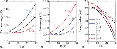
Figure 2. The perturbative calculation results (solid lines) and the numerical results (circles) of the energy of (a) electron and (b) hole states with the lowest radial quantum number as a function of the magnetic field for a 2D ring with  nm and
  nm. (c) The average radii of the electron (solid lines) and hole (dashed lines) states with the angular quantum number of 0 (squares), 1 (triangles), and
  (circles) as a function of the magnetic field.
Download figure:
Standard image High-resolution imageThe average radius of the electron and hole in the 2D ring varies for different angular quantum numbers and different magnetic fields as shown in figure 2(c). Because the magnetic-field-induced potential pushes both the electron and hole towards the center of the structure, the average radius decreases with increasing magnetic field. The average radius reduction of the electron is faster than the hole due to the larger kinetic energy of the former. According to equation (3), the energy oscillation period of the lowest single particle state is determined by its average radius. Figure 2(c) shows that the low-energy electron and hole states have a very similar average radius when  T. Therefore, the energy oscillation periods of the lowest electron and hole states are close to each other, which is seen in figures 2(a) and (b).
The energy of the non-interacting pair state  (
( , Eg: band gap of GaAs) is shown in figure 3(a). For the lowest pair state, the oscillating energy is observed with increasing B. By magnifying the region surrounded by the green square in figure 3(a), the total angular momentum transition from
  to 1 for the lowest-energy pair state is found in a narrow magnetic field range as shown in figure 3(b), which is attributed to the similar energy oscillation periods for the electron and hole states.
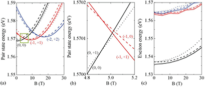
Figure 3. (a) Energy of the non-interacting pair states with total angular momentum  and
and  as a function of the magnetic field for a 2D ring with
  nm and
  nm. The combination of the electron and hole angular quantum number (
 ) is denoted for the low-energy pair states with
  . (b) The magnified figure of the region in the green square in (a). (c) Exciton energy as a function of the magnetic field for L = 0, −1 and
  in the same 2D ring. For both the pair states and the excitons, the states with L = 0, −1 and
  are plotted with the solid lines, dashed lines and dotted lines respectively. For each L, the first, second and third lowest states are plotted in black, red and blue colors, respectively.
Download figure:
Standard image High-resolution imageThe exciton energy of the 2D ring was calculated by the configuration interaction method as shown in figure 3(c). The A–B oscillation was not observed for the exciton ground state, but was found in the excited states, which agrees with [18]. By the configuration interaction method, we can also analyze the contribution of each pair state to the exciton ground state. We found that the wave functions of the pair states with the same L were mixed by the Coulomb interaction, and the crossing behavior between their energies was replaced by an anti-crossing behavior. So, the oscillation feature of the magnetic field dependence of the lowest pair state energy was smoothed, and the narrow B range for the non-zero L vanished. These resulted in the disappearance of the excitonic A–B effect, and the lowest exciton was always a bright one with  . Note that the electric-dipole transition between the exciton state and the ground state is allowed only for excitons with
  due to the conservation of angular momentum [21]. As an evidence of the Coulomb mixing, we found that as the magnetic field increased, the angular momentum of the largest contributing pair state for the exciton ground state changed from (
 ) to (
 ) and (
 ) for
) for  and 20 T, respectively. Our analysis showed that the Coulomb interaction was the reason for the vanishing A–B effect in the 2D ring.
3.2. QD-on-ring nanostructure
To avoid the Coulomb mixing among pair states, we may increase their kinetic energy interval by decreasing the width of the ring. But this method will simultaneously decrease the difference between the electron and hole average radii, which is undesirable for the A–B effect. If a ring with a small radius is used alternatively, the energy oscillation and the L transition of the exciton ground state may occur for a large magnetic field, which causes difficulty for experimental studies. Thus, in previous theoretical and experimental investigations, the visibility of the excitonic A–B effect was not clear for 3D rings [6, 22].
For a clear excitonic A–B effect in 3D nanostructures, we propose the use of the QD-on-ring nanostructure with an applied electric field (E) along the growth direction. The advantages of the coupled nanostructure stated in section 1 are also the conditions for the realization of a clear A–B effect. The recently reported QD-on-rings fulfill these conditions [11], thus the effect of the magnetic field on the exciton states of the QD-on-ring was numerically investigated to verify the appearance of the A–B effect.
Figure 4(a) shows the exciton energy of the QD-on-ring as a function of the magnetic field for  . Neither the energy oscillation nor the L transition was observed for the exciton ground state because the electron and hole were strongly bound (binding energy of 27 meV) in the QD part as can be seen from their average radii in figure 5(a).
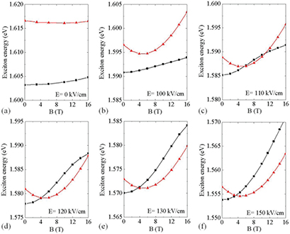
Figure 4. Energy of the lowest exciton states with the total angular momentum L = 0 and  in the QD-on-ring nanostructure as a function of the magnetic field for different applied electric fields (E). The exciton states with the total angular momentum L = 0 and
  are plotted with the solid squares and triangles, respectively.
Download figure:
Standard image High-resolution image
Figure 5. (a) The electron (solid lines) and hole (dashed lines) average radii of the lowest exciton state with L = 0 as a function of the magnetic field for  0 (in black color) and E = 120 kV
  (in red color). (b) The squared overlap integral of the lowest exciton state with L = 0 as a function of the magnetic field for
  0, 100, 110, 120, 130 and 150 kV
  .
.
Download figure:
Standard image High-resolution imageWhen an electric field is applied, the excitons have lower energy than those for  due to the Stark shift [21] as shown in figure 4. When
  , the largest contributing pair state for the lowest exciton state with
  is (
is ( ,
,  ), in which the electron is redistributed from the QD to the ring with the increasing electric field and the hole remains in the QD.
Figure 6(a) shows the pair state energy of the QD-on-ring for  kV
kV  as an example. When
  , the lowest electron and hole states are separated in the ring and QD, respectively. According to equation (1), the kinetic energy of single particles is inversely proportional to the square of its trajectory radius, thus the energy difference between the electron states (in the ring) with
  and
and  is smaller than that between the hole states (in the QD) with
  and
and  for
for  kV
kV  . This leads to a large energy difference between the lowest pair states (with
  ) and the corresponding higher energy pair states with nonzero-
 hole involved as shown in figure 6(a). By the charge separation, the Coulomb binding energy (7 meV) of the lowest exciton is smaller than this energy difference, which avoids the Coulomb mixing. At the same time, the magnetic field response of the lowest pair states with
  is dominated by that of the electron which is localized in the ring and has a larger trajectory radius, so a clear L transition is observed in figure 6(a). When Coulomb interaction is taken into consideration, the electron and hole remain spatially separated with a big difference in their average radii as shown in figure 5(a), which results in a large magnetic flux between their trajectories. So a clear A–B effect is observed for
  kV
kV  as shown in figure 6(b).

Figure 6. Energy of the (a) non-interacting pair states and (b) exciton states in the QD-on-ring nanostructure as a function of the magnetic field for the electric field  kV
kV  . The states with the total angular momentum L = 0 and
  are plotted with the black squares and red triangles, respectively. For each L, the lowest state and the excited state are plotted with the solid lines and the dashed lines, respectively. The combination of the electron and hole angular quantum numbers (
 ) is denoted for the pair states.
Download figure:
Standard image High-resolution image
The magnetic-field-induced potential leads to the decreasing average radii of both the electron and hole as shown in figure 5(a). Furthermore, the squared overlap integral of the lowest exciton ( ) increases with the magnetic field as shown in figure 5(b). This leads to an increasing binding energy and the effect of the Coulomb mixing becomes obvious, shown as the anti-crossing behavior between the first and second lowest excitons (L = 0) for
  T in figure 6(b). The influence of the magnetic field on the distribution of the low-energy single particles partly cancels for the electric-field-induced charge separation.
The lowest exciton for  is always a bright exciton. When the L transition occurs for the exciton ground state at
  T for
T for  kV
kV  , this bright exciton with a non-negligible squared overlap integral turns dark. Therefore, we propose an excitonic A–B effect with the moderate external fields, which may be verified by the experimental observation of the emission spectra by tuning the applied electric field.
4. Conclusion
By the first-order perturbation theory and the configuration interaction method, we derived the magnetic-field dependence of both the non-interacting electron–hole pair-state energy and the exciton energy in a two-dimensional quantum ring. We showed that the Coulomb interaction between the electron and hole mixes the wave functions of pair states with the same total angular momentum, which modifies the magnetic-field dependence of the exciton energy and results in the disappearance of the excitonic Aharonov–Bohm (A–B) effect.
To avoid this situation and observe a clear excitonic A–B effect, we proposed the use of a coupled nanostructure of a quantum dot located on the top of a quantum ring, which was recently reported by an experimental study. We showed that by applying a static electric voltage perpendicular to the ring we can simultaneously achieve the partial separation of the electron and hole wave functions to reduce the Coulomb mixing and the control of the average radius of their trajectories to enhance the A–B effect. We showed that we can observe the excitonic A–B effect with moderate experimental conditions of an electric field of 120 kV  and a magnetic field of 4 T.
Acknowledgments
This study was supported by JSPS KAKENHI Grant Number 16H02203, JSPS Japan-Russia Research Cooperative Program, and JST SICORP.
Appendix. Single particle states in a 2D ring
In the cylindrical coordinates ( ), the single particle wave function has a form of
  for
for  , where l is the angular momentum and n is the radial quantum number. The radial wave function
  satisfies
The solution of equation (A.1) is given by [23]
where  ,
,  ,
,  and
and  are the Bessel function of the first and second kind,
  and
and  are the modified Bessel function of the first and second kind.
By using the boundary condition of the continuity of the wave function and its first-order derivative at Ri and Ro, the eigen energy and the wave function can be obtained by solving a secular equation  . G is given by
where  and
and  are the effective mass for the ring and the barrier layer, respectively.