
Abstract
The spin textures of ultra-thin magnetic layers exhibit surprising variety. The loss of inversion symmetry at the interface of the magnetic layer and substrate gives rise to the so-called Dzyaloshinskii–Moriya interaction which favors non-collinear spin arrangements with unique rotational sense. Here we review the application of spin-polarized scanning tunneling microscopy to such systems, which has led to the discovery of interface-induced chiral domain walls and spin spirals. Recently, different interface-driven skyrmion lattices have been found, and the writing as well as the deleting of individual skyrmions based on local spin-polarized current injection has been demonstrated. These interface-induced non-collinear magnetic states offer new exciting possibilities to study fundamental magnetic interactions and to tailor material properties for spintronic applications.
Export citation and abstract BibTeX RIS
1. Introduction
Magnetism in low-dimensions is a fascinating topic: Even in apparently simple systems such as atomic layers the nearest neighbor distance, the symmetry, and the hybridization with the substrate can play a crucial role for the magnetic properties. This may lead to a variety of magnetic structures, from the ferromagnetic and antiferromagnetic state to complex, non-collinear spin textures. While the formation of a ferromagnetic or antiferromagnetic state can be the result of a dominating nearest neighbor exchange interaction, complex magnetic structures often reflect a situation of competing magnetic interactions. Recently an increasing number of reports on novel approaches in spintronics and information technology are based on concepts of employing chirality or topological protection, e.g. [1–6]. Two main characteristics of systems exhibiting these properties should be mentioned: first, they are extremely well defined, as the respective domain walls, spin spirals or skyrmions always occur with a specific material-intrinsic rotational sense and second, an additional stability can arise in such systems due to topological protection.
The notion of spintronics is to exploit the spin rather than the charge for future technology. Non-collinear magnetic states are known to interact very efficiently with spin-polarized currents, and domain walls with unique rotational sense can be moved with lateral currents at much larger speed compared to conventional ones as the Walker breakdown is suppressed [5–8]. For skyrmions it has been shown that much smaller current densities are needed for a lateral movement [9–12] compared to domain walls which makes them interesting candidates for, e.g., race track memory concepts [1, 13, 14]. As a prerequisite for the use in applications, recently the writing and deleting of single magnetic skyrmions has been demonstrated [4].
In this review we will discuss how the competition of various magnetic interactions can lead to interface-induced non-collinear magnetic order (section 2) and how the chirality or topological protection is derived from a phenomenological viewpoint (section 3). Section 4 briefly describes the experimental methods able to investigate complex magnetic order with unit cells on the atomic scale, namely spin-polarized scanning tunneling microscopy (SP-STM) and STM exploiting the tunneling anisotropic magnetoresistance (TAMR). The first combines magnetic sensitivity with the high lateral resolution of STM while the latter reveals variations of the magnetization axes. Sections 5, 6 and 7 review our contributions to the field of chiral domain walls, spin spirals, and magnetic skyrmions, respectively, and section 8 provides a short summary.
2. Magnetic interactions
Magnetic interactions are the origin of any magnetic state. For ultra-thin magnetic films they can be obtained quantitatively for a given system by mapping the results of ab initio electronic structure calculations on a two-dimensional classical Heisenberg model (see e.g. [3, 15]). This makes it possible to search for the origin of a specific magnetic ground state, i.e. to find out which interactions dominate or compete. This, of course, facilitates a general understanding of magnetism and aims at a tailoring of magnetic properties in the future.
A fundamental magnetic interaction between atomic spins  is the pair-wise Heisenberg exchange
Depending on the sign of the nearest neighbor interaction  the ground state is ferromagnetic or antiferromagnetic, see figure 1. However, on a triangular lattice a negative
  leads to geometrical frustration and the non-collinear 120°-Néel state is favored. When the second-nearest neighbor interaction
  is on the same order as
  this may lead to frustration and a homogeneous spin spiral can be the magnetic ground state, figure 2. Since J is isotropic the spin spiral can rotate either in one direction or the other, and it may be helical or cycloidal, i.e. the spins may rotate in a plane perpendicular or parallel to the spin spiral propagation vector
  .
.

Figure 1. Nearest neighbor Heisenberg exchange J1. (a) When J1 is positive a ferromagnetic ground state is realized while (b) negative J1 leads to antiferromagnetic order. (c) For hexagonal atomic arrangement antiferromagnetic nearest neighbor coupling leads to geometrical frustration and the Néel state with 120° between adjacent spins is the magnetic ground state.
Download figure:
Standard image High-resolution image
Figure 2. Competition between nearest and next-nearest neighbor exchange J1 and J2, respectively, leads to frustration and a spin spiral state can become the magnetic ground state, see bottom panel. The rotation of magnetic moments can be realized in several ways, and all states are degenerate in energy.
Download figure:
Standard image High-resolution imageThe Dzyaloshinskii–Moriya (DM) interaction arises due to spin-orbit interaction and is described by
It links the spins via a vector product and may play a role when the inversion symmetry is broken, which is always the case at surfaces and interfaces. It favors a 90°-spin spiral and the rotational sense is determined by the sign of D, see figure 3.
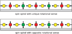
Figure 3. The DM interaction favors a 90° rotation between adjacent spins and the rotational sense is determined by the sign of the DM vector.
Download figure:
Standard image High-resolution imageOf course, the competition between Heisenberg exchange and DM-interaction may lead to spin spirals with any angle between adjacent spins. The magnetic ground state is often derived from the energy dispersion of spin spirals along high symmetry directions, see e.g. [16–18]. When the energy minimum is found at high symmetry points of the two-dimensional Brillouin-zone, characteristic magnetic states are obtained, as exemplified in figure 4 for hexagonal symmetry: at the  point adjacent spins enclose an angle φ of 0°, corresponding to the ferromagnetic state (FM), at
  the Néel state is located with 120° between spins, and at
  the 180° result in a row-wise antiferromagnetic (RWA) configuration.
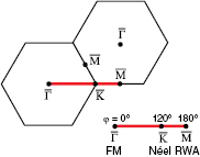
Figure 4. The two-dimensional Brillouin-zone of a hexagonal lattice. The red line indicates a typical cut for the calculation of the spin spiral dispersion, where the angle φ between adjacent spins ranges from 0° at the  -point (ferromagnetic FM) via 120° at the
  -point (Néel state) to 180° for the
  -point (row-wise antiferromagnetic order RWA).
Download figure:
Standard image High-resolution imageWhen the DM interaction is comparably small or the anisotropy energy
plays a significant role a system can also form an inhomogeneous spin spiral, where the variation of the angle between adjacent spins depends on the quantization axis. In an extreme case this may lead to collinear magnetic domains which are separated by walls with unique rotational sense due to the DM interaction, i.e. chiral domain walls. This means that a pair of domain walls will always fulfill a 360° rotation of the magnetization as the walls must have the same rotational sense. If in such a case the domains are ferromagnetic also contributions from the dipolar energy
need to be considered for the magnetic properties of the system.
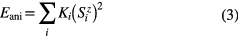
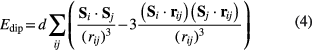
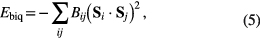
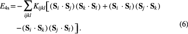
Higher-order Heisenberg interactions are typically neglected but recently it has been shown that they can become important and contribute to the energy landscape and ground state formation [15, 19]. In the extended Heisenberg model the next higher-order interactions are the biquadratic and four-spin interactions, which involve two and four nearest neighbors, respectively, as is obvious from their Hamiltonians:
In the Heisenberg model spin spirals (single-  states) are degenerate with superpositions of symmetry-equivalent spin spirals (multi-
  states); however, the higher order interactions can lift this degeneracy and depending on the sign of the interaction favor one over the other state [16].
3. Chirality and topological protection
A phenomenological view of the symmetry of spin spirals helps to understand the DM related selection rules from Moriya [20, 21]. Figure 5 sketches helical (left) and cycloidal (right) spin spirals. Whereas helical spirals can exist with two opposite rotational senses, there is only one type of cycloidal spiral possible (the ones shown in figure 5 can be transformed into each other by rotation and translation). However, such a cycloidal spiral can be placed onto a surface (dark blue plane in figure 5) in two different ways, i.e. due to the breaking of the inversion symmetry of the environment two distinct rotational senses of cycloidal spin spirals are generated. Looking at the yellow ribbons symbolizing the different spirals it becomes evident that the two helical spirals (with or without surface) are mirror images of each other, meaning that they are degenerate in energy. Contrary to that, the two cycloidal spirals on the surface cannot be linked by any symmetry operation, proving the possibility to have different energy, i.e. one rotational sense is favored due to the DM-interaction and the other one does not occur as it possesses higher energy. The same arguments also hold for domain walls induced by the DM interaction, which are found with only one rotational sense. They are typically referred to as chiral domain walls, even though they are not chiral in a strict sense, as they possess a mirror plane.

Figure 5. Sketch of helical (left) and cycloidal (right) spin spirals, where the propagation direction is perpendicular to or within the plane of the spin rotation, respectively. While the helical spin spirals are degenerate in energy even when they are on a surface (dark blue plane), the cycloidal spin spirals can have a different energy due to the DM interaction, i.e. one cycloidal spin spiral can be favored while the other one has a higher energy on the surface.
Download figure:
Standard image High-resolution imageSequences of domain walls and spin spirals with unique rotational sense (see sections 5 and 6, respectively) are somewhat robust in external magnetic fields compared to systems where the rotational sense alternates, see figure 6. In both cases the area with spins parallel to the external magnetic field grows at the expense of the oppositely magnetized area. However, while in the case of alternating domain walls they can easily annihilate, see figure 6(b), for systems with unique rotational sense a 360°-domain wall is generated between domains along the external field (c). This knot in the magnetization can be directly expressed by the topological index
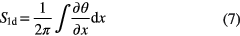
where θ is the angle between adjacent moments and x is the spatial coordinate. In the first case, figure 6(b), S is equal to 0 and in the latter, figure 6(c), it is 1. In other words, a system with domain walls of unique rotational sense is topologically protected when the spin orientation is confined to a plane, while two domain walls with opposite rotational sense are topologically trivial as they can be continuously transformed into the ferromagnetic state (also S = 0).
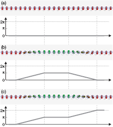
Figure 6. Winding number in one dimension (adopted from [22]). (a) A ferromagnetic configuration has a constant angle of 0 between adjacent spins, thus S = 0 and the state is topologically trivial. (b) In a ferromagnetic system with two oppositely rotating domain walls the angle of magnetic moments changes from 0 to π and back to 0, thus S = 0. This state can be transformed into the FM state by a continuous rotation of the central domain. (c) When the spins in the two domain walls rotate with the same rotational sense the angle changes from 0 to 2π, S = 1 and the state is topologically protected if the spin orientation is confined to a plane (all taken from [23]).
Download figure:
Standard image High-resolution imageExtending this idea to two-dimensional magnetic structures results in the description of skyrmions and antiskyrmions [14] (see section 7), see figure 7. Here the topological index or winding number is defined as
where  is the normalized magnetic vector field and x, y are the spatial coordinates. Note that in two dimensions the spin spiral state (b) has S = 0, i.e. it is not topologically protected from transforming into the ferromagnetic state. The skyrmion and antiskyrmion, figures 7(c) and (d), both have a winding number of |1|, but with opposite sign. Analyzing the angle between nearest neighbors shows that both have the same energy in terms of isotropic Heisenberg exchange interaction, but differ in energy when the DM interaction is considered and the skyrmion with the preferred rotational sense gains more energy than an antiskyrmion.
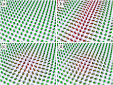
Figure 7. Topological index in two dimensions. (a) The ferromagnetic state and (b) the spin spiral state are topologically trivial with S = 0. (c) The skyrmion and (d) the antiskyrmion state have |S| = 1 and are topologically protected, i.e. they cannot be transformed continuously into an S = 0 state (all taken from [23]).
Download figure:
Standard image High-resolution image4. Experimental method
We use scanning tunneling microscopy (STM) to study magnetism down to the atomic scale. For the investigation of non-collinear spin textures one can either use a magnetic tip and perform SP-STM and directly image the magnetic state [24, 25], or one can employ a non-magnetic tip and exploit the tunneling anisotropic magnetoresistance (TAMR) effect to distinguish atoms with different magnetization axes [26, 27].
4.1. Spin-polarized scanning tunneling microscopy
Essentially SP-STM is STM performed with a magnetic tip [24, 25]. When both surface and tip are magnetic, the imbalance of spin-up and spin-down electrons around the Fermi level leads to an additional contribution to the tunnel current, which depends on the angle of tip and local surface magnetization. This is known as the tunnel magnetoresistance (TMR) effect. In an STM experiment this combines ultimate resolution with spin-sensitivity, which allows to investigate magnetic phenomena of conducting samples down to the atomic length scale. Magnetic tips can be made from bulk material, or prepared by coating non-magnetic tips with a thin film of magnetic material. Ferromagnetic materials like Fe as well as antiferromagnets such as Cr are used for tips. Spin-polarized tips can also be obtained by picking up magnetic material from the surface. The choice of magnetic tip depends on the designated experiment. As a rule of thumb, samples which do not respond to external magnetic fields are investigated with ferromagnetic tips, while antiferromagnetic tips are employed on magnetically soft materials. With this approach the magnetostatic interaction between tip and sample system is minimized and in addition the magnetization of one electrode can be controlled by an external field, while the other stays unchanged.
The most common measurement modes of SP-STM are constant current images, maps of the differential conductance (dI/dU maps) and dI/dU(U) spectroscopy. Constant current imaging is ideally suited for atomic scale spin textures like antiferromagnets or non-collinear magnetic states. Typically low bias voltages are used to limit the number of contributing electronic states. dI/dU maps are a good choice for larger magnetic structures (e.g. magnetic domains) or when working on stepped surfaces. The dI/dU signal is measured by lock-in technique, adding a small modulation to the tunnel bias voltage. Here the magnetic contrast can be optimized by selecting highly spin-polarized electronic states at specific energies, but the scan speed is now limited by the lock-in time constant. Spin-polarized spectroscopy gives access to the energy dependence of the spin-polarization.
4.2. Tunneling anisotropic magnetoresistance
Using a standard non-magnetic STM tip, e.g. polycrystalline tungsten, one can also obtain information about non-collinear magnetic states [26, 27]. Due to spin-orbit coupling the local mixing of electronic bands is different for atoms with, for instance, a magnetization direction out-of the surface plane, compared to an atom with a magnetization in the surface plane. This is known as the TAMR effect and gives rise to locally different density of states which is detected via the tunnel current. For spin spirals the TAMR signal varies laterally with twice the periodicity of the magnetic SP-STM signal.
There are some advantages of using the TAMR to study non-collinear magnetic order: first, the preparation of a magnetic tip can be omitted, second, there is no stray field from the tip that may influence the magnetic state of the sample, and third, one can exclude spin-transfer torque effects. Of course the major disadvantage is that the full three-dimensional spin state cannot be derived from such a measurement. However, TAMR can be used as a crosscheck, since typically there is some voltage where it can be observed for a given non-collinear structure. For data analysis one has to be careful not to mix up the origin of a measured contrast, as of course also a magnetic tip (or assumed magnetic tip) can show TAMR contrast.
5. Chiral domain walls
Recently there has been quite some interest in chiral magnetic domain walls [5–7, 28]. Here we recall the early SP-STM work that experimentally determined the unique rotational sense of the walls in the system of an Fe double layer (DL) on W(1 1 0) [29]. The magnetic pattern of this system consists of a regular sequence of out-of-plane magnetized domains separated by domain walls running along ![$\left[1\bar{1}0\right]$](https://content.cld.iop.org/journals/0953-8984/26/39/394002/revision1/cm497111ieqn016.gif) [30–32]. The average distance between two walls amounts to about 20 nm. While it was shown in earlier studies that the in-plane component of the walls alternates and the rotational sense is the same for a given sample, the absolute magnetization direction within the walls could not be measured because in the respective SP-STM experiments the azimuthal component of the tip magnetization was unknown. For this reason it remained an open question whether the domain walls are of Bloch- or Néel-type, i.e. if the magnetization behaves like a helix or a cycloid, see figure 5.
[30–32]. The average distance between two walls amounts to about 20 nm. While it was shown in earlier studies that the in-plane component of the walls alternates and the rotational sense is the same for a given sample, the absolute magnetization direction within the walls could not be measured because in the respective SP-STM experiments the azimuthal component of the tip magnetization was unknown. For this reason it remained an open question whether the domain walls are of Bloch- or Néel-type, i.e. if the magnetization behaves like a helix or a cycloid, see figure 5.
To experimentally determine the nature of the domain walls in the Fe DL on W(1 1 0) SP-STM experiments were performed under ultra-high vacuum conditions at T = 4.7 K in the magnetic field of a superconducting triple axes magnet [29, 33, 34]. This setup allows full control of the tip magnetization vector in SP-STM experiments. Figure 8 presents a field-dependent series of spin-polarized dI/dU maps of the Fe DL. An external magnetic field was applied along different in-plane directions as indicated, to align the tip magnetization  accordingly. This is a well established procedure for SP-STM experiments in fields oriented along the surface normal [35] which is generalized here to arbitrary field directions. The magnetic field B = 150 mT was chosen such that it is weak enough not to affect the magnetic structure of the sample but strong enough for the alignment of
  . For
. For  pointing along the [0 0 1] axis, (a) and (b), we observe a strong domain wall contrast (black and white lines along the
 ![$\left[1\bar{1}0\right]$](https://content.cld.iop.org/journals/0953-8984/26/39/394002/revision1/cm497111ieqn020.gif) axis). By comparison of (a) and (b) one observes a contrast reversal due to the reversal of
axis). By comparison of (a) and (b) one observes a contrast reversal due to the reversal of  . The domain wall contrast vanishes with
  being rotated by 90°along the
 ![$\left[1\bar{1}0\right]$](https://content.cld.iop.org/journals/0953-8984/26/39/394002/revision1/cm497111ieqn023.gif) axis, (c) and (d ). Instead, one observes a weak stripe-like pattern in the areas of the out-of-plane magnetized domains due to a residual perpendicular component of
axis, (c) and (d ). Instead, one observes a weak stripe-like pattern in the areas of the out-of-plane magnetized domains due to a residual perpendicular component of  . In conclusion, the magnetization in the domain walls rotates through the [0 0 1] rather than the
 ![$\left[1\bar{1}0\right]$](https://content.cld.iop.org/journals/0953-8984/26/39/394002/revision1/cm497111ieqn025.gif) direction, proving that the domain walls are of Néel-type, i.e. the magnetization rotates like a cycloid.
direction, proving that the domain walls are of Néel-type, i.e. the magnetization rotates like a cycloid.

Figure 8. Spin-polarized dI/dU maps of the Fe DL on W(1 1 0) (red areas correspond to DL and black to other Fe thickness); B indicates the in-plane orientations of the external magnetic field B = 150 mT which aligns the tip magnetization. (a), (b) Domain walls show up in the DL as black and white lines along the ![$\left[1\bar{1}0\right]$](https://content.cld.iop.org/journals/0953-8984/26/39/394002/revision1/cm497111ieqn026.gif) direction; they invert the contrast from (a) to (b). (c), (d) Vanishing domain wall contrast. Tunnel parameters: U = + 0.55 V, I = 0.5 nA (all images taken from [29]).
direction; they invert the contrast from (a) to (b). (c), (d) Vanishing domain wall contrast. Tunnel parameters: U = + 0.55 V, I = 0.5 nA (all images taken from [29]).
Download figure:
Standard image High-resolution imageFigure 9 displays a second series of field dependent measurements to investigate the sense of rotation of the domain walls. The measurements were done on the same sample and using the same tip, bias voltage and tunnel current as for the series shown in figure 8. Now, the field was applied normal to the sample surface and swept in the range Bz = 0 − 350 mT. In contrast to the measurement series shown in figure 8 now both  and the sample magnetization
  are affected by the external field. Domains with
  being parallel (antiparallel) to the field grow (shrink). Thus, the direction of
  can be identified for all domains. On the tip side, sweeping the field causes
  to increasingly rotate into the perpendicular direction. Consequently, the in-plane domain wall contrast gradually disappears and is eventually replaced by an out-of-plane contrast, allowing to image the domains rather than the domain walls, figures 9(c) and (d). The large domains with
  being parallel to the field appear bright whereas residual domains, being shrunken to mere lines and with
  being antiparallel to the field, appear dark. This observation can be generalized such that for the tip-sample combination in our experiment, at the given bias voltage, bright colors (high dI/dU signal) indicate a parallel alignment of
  and
and  while dark (low dI/dU signal) corresponds to an antiparallel alignment. Applying this result to the measurement shown in figure 8(a) one can identify the direction of
  also for the domain walls. Combining the knowledge from these two experiments (figures 8 and 9) we can conclude that the Fe DL exhibits only right-rotating Néel-type walls
  and
and  [29, 34].
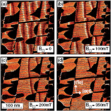
Figure 9. Spin-polarized dI/dU maps of the Fe DL on W(1 1 0) measured for variable field values B applied normal to the surface, as indicated in (a)–(d). The domains parallel to B grow while antiparallel domains shrink. The tip magnetization (and hence the magnetic sensitivity) is gradually rotated from in-plane to out-of-plane due to the applied magnetic field. Tunnel parameters: U = + 0.55 V, I = 0.5 nA (all images taken from [29]).
Download figure:
Standard image High-resolution imageThis experimental finding of cycloidal walls with unique rotational sense immediately suggests that the DM interaction is the relevant factor determining the rotational sense of the walls, see section 3. Indeed, starting from phenomenological DM vectors [20] Monte-Carlo simulations showed that the unique rotational sense can be explained as a consequence of the DM interaction [36]. By density functional theory (DFT) combined with micromagnetic calculations the DM vector was determined from first principles [37]. The magnetic ground state was predicted to be ferromagnetic although within numerical accuracy a non-collinear spin spiral ground state could not be ruled out. However, two domains of opposite magnetization induced in this system by appropriate boundary conditions were found to be separated by right-rotating Néel-type domain walls extending along the ![$\left[1\bar{1}0\right]$](https://content.cld.iop.org/journals/0953-8984/26/39/394002/revision1/cm497111ieqn039.gif) axis, in agreement with the experiment [29].
axis, in agreement with the experiment [29].
It appears to be an academic question whether this spin configuration of the extended Fe DL should be classified as an inhomogeneous spin spiral or a periodic arrangement of chiral domain walls. In any case, isolated chiral domain walls can be prepared by lateral structuring. Figure 10(a) shows an array of narrower Fe DL wires prepared by step flow growth on a W(1 1 0) surface. Due to a lower shape anisotropy, the domain wall density decreases with decreasing wire width while the chirality of the walls is preserved. Chiral domain walls have attracted renewed interest recently due to their unique current-induced dynamic properties [5, 6].
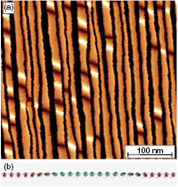
Figure 10. Chiral domain walls in Fe DL wires on W(1 1 0). (a) Spin-polarized dI/dU map. The density of domain walls decreases with decreasing DL wire width while the chirality is preserved. Tunnel parameters: U = + 0.7 V, I = 0.3 nA, T = 14 K. (b) Schematic side view of two right rotating domain walls.
Download figure:
Standard image High-resolution image6. Spin spirals
Spin spirals can arise due to the competition between isotropic Heisenberg exchange and DM interaction [38]. In first approximation the ratio of these two interactions sets the period of the magnetic state [36]. Such interface-induced spirals with unique rotational sense have been found in monolayer [38–40] or double-layer [4, 19] high atomic films and chains [3] on heavy element substrates, as will be presented in this Section. In principle, spin spirals that originate from a competition between nearest and next-nearest neighbor Heisenberg exchange are also possible, but to our knowledge there has been no experimental validation of such a magnetic state in ultra-thin films.
6.1. Spin spirals in monolayers on tungsten
The first interface-induced homogeneous spin spiral ground state was observed in the system of one monolayer of Mn on a W(1 1 0) surface [38], i.e. the same heavy element substrate that supported the Fe DL exhibiting the chiral domain walls, see section 5. An atom in the (1 1 0) surface layer of a bcc crystal has four nearest neighbors within the layer, see black lines in figure 11(a). Following the phenomenological symmetry selection rules [20] the DM vector between these nearest neighbors is restricted to lie in the surface plane. However, typically an effective DM interaction along the high symmetry directions can be used to describe such a system [36–38], see red arrows in figure 11(a).

Figure 11. Spin spirals on W(1 1 0). (a) Sketch of a bcc(1 1 0) surface with effective DM vectors in red. (b), (c) Mn-ML/W(1 1 0): derivatives of constant-current images with magnetic tip (Fe/W) sensitive to (b) the in-plane and (c) the out-of-plane component of the sample magnetization (U = − 2 mV, I = 20 nA, T = 13 K, the blue circle acts as position marker). (d) Sketch of the spin spiral of the Mn-ML/W(1 1 0). (e) Cr-ML/W(1 1 0): derivative of constant-current image with magnetic tip (Fe/W) (U = + 3 mV, I = 10 nA, T = 12 K, B = 0 T). (f) Sketch of the spin spiral of the Cr-ML/W(1 1 0).
Download figure:
Standard image High-resolution imageIn an SP-STM measurement of the Mn ML on W(1 1 0) the magnetic signal consists of fine lines with twice the atomic lattice periodicity running along [0 0 1], see figure 11(b). This pattern vanishes periodically and as an in-plane magnetized Fe tip was used for this measurement we can conclude that the fine lines stem from in-plane spins with nearly antiferromagnetic order. Sample areas where no magnetic contribution to the tunnel current is measured have spins with a significant out-of plane component. Experimentally this hypothesis can be proven by a measurement using an out-of-plane magnetized tip at the same sample position. While in an SP-STM experiment a ferromagnetic tip can be aligned in an external magnetic field [29, 35] this sample is close to an antiferromagnet and thus does not respond easily to an external magnetic field. In this way different magnetic components of the sample can be probed at different magnetic fields. The image acquired with an out-of-plane magnetized tip, figure 11(c), qualitatively resembles the first measurement (b) with fine lines that vanish periodically, but now the magnetic signal is phase-shifted to a position where no contrast was observed with the in-plane magnetized tip. The combined information of these experiments proves the spin spiral order with a propagation vector along ![$\left[1\bar{1}0\right]$](https://content.cld.iop.org/journals/0953-8984/26/39/394002/revision1/cm497111ieqn040.gif) . Experiments on several islands with the identical magnetic tip show that the spin spiral rotates with only one rotational sense, in accordance with DFT calculations that find a left-rotating cycloidal spiral with the DM vector along [0 0 1] [38]. The underlying mechanism for the formation of the cycloidal spin spiral with unique rotational sense in the Mn monolayer on W(1 1 0), where adjacent spins enclose an angle of ≈ 170° (see sketch in figure 11(d)), is the competition of antiferromagnetic nearest neighbor Heisenberg exchange and DM interaction.
. Experiments on several islands with the identical magnetic tip show that the spin spiral rotates with only one rotational sense, in accordance with DFT calculations that find a left-rotating cycloidal spiral with the DM vector along [0 0 1] [38]. The underlying mechanism for the formation of the cycloidal spin spiral with unique rotational sense in the Mn monolayer on W(1 1 0), where adjacent spins enclose an angle of ≈ 170° (see sketch in figure 11(d)), is the competition of antiferromagnetic nearest neighbor Heisenberg exchange and DM interaction.
To investigate whether the DM interaction is generally to be considered when studying the magnetism of monolayers, the Cr monolayer was also investigated which again grows pseudomorphically on W(1 1 0) [40]. The spin-resolved image in figure 11(e) shows stripes very similar to the ones observed for Mn on W(1 1 0), (b) and (c), indicating local antiferromagetic order. However, here the stripes show a modulation along the [0 0 1] direction. Following the arguments of [38] we interpret this as a DM-driven spin spiral propagating along the [0 0 1] direction, i.e. we have a cycloidal spin spiral with unique rotational sense. The propagation direction is perpendicular to that observed for the Mn monolayer, thus also the direction of the DM vector is perpendicular, i.e. for Cr it is along ![$\left[1\bar{1}0\right]$](https://content.cld.iop.org/journals/0953-8984/26/39/394002/revision1/cm497111ieqn041.gif) . The reason for this rotation could be a different easy axis: while for Mn the spins favor an alignment along
. The reason for this rotation could be a different easy axis: while for Mn the spins favor an alignment along ![$\left[1\bar{1}0\right]$](https://content.cld.iop.org/journals/0953-8984/26/39/394002/revision1/cm497111ieqn042.gif) [38, 41], the Cr spins seem to avoid this direction.
[38, 41], the Cr spins seem to avoid this direction.
To study the influence of the symmetry of the atomic lattice on spin spiral states the pseudomorphic Mn monolayer on W(0 0 1) was investigated, which has a four-fold symmetry [39]. Again we observe a uniaxial spin spiral in SP-STM measurements made up of atoms with magnetization components in the surface plane and normal to the surface. The underlying cycloidal spin spiral is sketched in figure 12(a), and ab-initio calculations have confirmed that it has a unique rotational sense due to the DM interaction [39]. On a larger sized image, figure 12(b), one can see a labyrinth pattern due to spin spirals propagating along the two equivalent 〈1 1 0〉 directions of the surface. Note that in addition to the magnetic signal we obtain atomic resolution for this sample system, see inset, which has proven to be rather difficult for other systems. This system is distinct from the Mn and Cr monolayers on W(1 1 0) in two ways: First, the deviation of the angles between nearest neighbors is large with roughly 36°, compared with about 7° and 4° off the antiferromagnetic collinear state (i.e. about 173° and 176° between adjacent spins) for the Mn and Cr monolayer on W(1 1 0). Second, due to the four-fold symmetry we observe two rotational domains of the spin spiral; this is not an obvious behavior, as within the Heisenberg model a single Q-state, i.e. a spin spiral, is degenerate with multi-Q states, i.e. superpositions of spin spirals (see section 2). However, in a real system the higher-order interactions can lead to an energy difference between a single- and a multi-Q state [16], and in the case of the Mn ML on W(0 0 1) these parameters favor the formation of a uniaxial spin spiral instead of the formation of a three-dimensional spin structure. Note that often it is not trivial to form such a multi-Q state, as intra-atomic exchange interaction can become very large when the magnetic moments of the atoms are varied [15].

Figure 12. Mn monolayer on W(0 0 1). (a) Sketch of the spin spiral ground state. (b) Spin-resolved STM measurement of 1 ML Mn/W(0 0 1). Constant-current image with magnetic tip sensitive to the out-of-plane component of the sample magnetization (U = + 0.1 V, I = 0.1 nA, T = 13 K, B = − 2 T); the inset is a magnified view of the indicated region to demonstrate the atomic corrugation.
Download figure:
Standard image High-resolution image6.2. Spin spiral in bi-atomic Fe chains on Ir(0 0 1)
In reduced dimensions finite size effects of spin spirals are expected to arise. It is straightforward to study this in a one-dimensional object with a spin spiral ground state which thus has two defined ends, in contrast to e.g. round shaped two-dimensional islands containing a uniaxial spin spiral. The formation of one-dimensional chains can be induced using highly anisotropic substrates such as the reconstructed Ir(0 0 1) surface [43]. The magnetic ground state of bi-atomic Fe chains on the reconstructed Ir(0 0 1) surface is a cycloidal spin spiral with three atom periodicity, see figure 13(a) [3]. Again DFT revealed as origin for the angle of about 120° between adjacent magnetic moments the competition of magnetic exchange and DM interactions. For this system it is not sufficient to use an effective DM vector arising from nearest neighbors interaction. Instead, the DM interaction between atoms further apart need to be considered to accurately describe the system. The magnetic superstructure of the Fe chains cannot be observed in an SP-STM experiment at 8 K without external magnetic field. Due to the reduced dimension the system behaves superparamagnetically and thermally switches between equivalent states, as revealed by Monte-Carlo simulations. Only in an external magnetic field the net magnetic moment of a finite chain has a preferential direction which induces an asymmetry in the switching lifetimes, allowing one to observe a magnetic signal in the time-averaged STM measurement, see figure 13(b).

Figure 13. Bi-atomic Fe chains on Ir(0 0 1). (a) Sketch of the 120° spin spiral ground state. (b) SP-STM measurement at T = 8 K (topography color-coded with dI/dU signal) of Fe chains with external magnetic field of B = + 2 T (U = + 0.5 V, I = 5 nA, T = 8 K); in magnetic field the three-atom magnetic periodicity of the spin spiral is visible (taken from [23]). (c) Effective chain anisotropy for three exemplary chain lengths (taken from [42]). (d) SP-STM measurements of an ensemble of Fe chains at B = 0 T and B = 4 T (U = + 0.5 V, I = 0.5 nA, T = 4.2 K); the bottom graph shows the measured magnetic corrugation amplitude of three exemplary chains as a function of external magnetic field.
Download figure:
Standard image High-resolution imageUsing micromagnetic simulations [44] an interesting finite size effect of these chains was discovered [23]: The three atom periodicity of the magnetic structure leads to quite remarkable properties of the chains as a function of the exact number of atoms in the chain: while the on-site anisotropy of the Fe atoms in the chain is out-of-plane, the spin spiral leads to an effective chain anisotropy that alternates with chain length between out-of-plane, in-plane, and nearly quenched, see polar plot of the effective anisotropy in figure 13(c). This manifests in a quite different response to an external out-of-plane magnetic field: while the two-fold degenerate chains with effective out-of-plane net magnetic moment can be aligned in the direction of an external magnetic field, this is naturally much more difficult for the chains with effective in-plane anisotropy. The chains with quenched effective anisotropy also have a vanishing net magnetic moment and are four-fold degenerate due to symmetry reasons, which makes them somewhat inert with respect to external magnetic fields. This effect is observed qualitatively for isolated Fe chains [42]. However, in an ensemble of Fe chains also the coupling to adjacent chains via the substrate may play a role for the magnetic field dependence of the magnetic corrugation, see figure 13(d), and it is not straightforward to disentangle the different contributions.
6.3. Néel order in the Fe ML on Re(0 0 0 1)
The ground state for pair-wise antiferromagnetic interaction on a triangular lattice is the Néel state, see figures 1 and 14(a). This state can also be described as a 120° spin spiral propagating along a closed packed row of the hexagonal lattice, see figure 4, i.e. in the spin spiral dispersion this state is located at the  -point. This magnetic ground state can be identified in an SP-STM experiment [46] and has not only been found for prototype antiferromagnets like Mn [47] and Cr [48], but also for Fe in a hexagonal monolayer on Re(0 0 0 1), see figure 14(b) [18, 45].

Figure 14. The Néel state is the ground state of antiferromagnetic coupling on a hexagonal lattice. (a) Sketch of a Néel state. (b) SP-STM constant-current image of the Néel state in one monolayer on Fe on Re(0 0 0 1) measured with a Cr-bulk tip (U = 4 mV, I = 42 nA, T = 4.2 K, taken from [45]).
Download figure:
Standard image High-resolution imageFor a fcc(1 1 1) or hcp(0 0 0 1) surface the DM vector is confined to a plane perpendicular to nearest neighbor bonds. According to the three-sites mechanism it is likely to be normal to a plane spanned by two surface and the closest subsurface atoms [49], i.e. on a hexagonal surface the DM vector is perpendicular to the nearest neighbor bond and alternates slightly between the two out-of-plane directions with a dominant in-plane component. An experimental observation of unique rotational sense in such a system has not been reported up to now.
6.4. Conical spin spiral in the Mn DL on W(1 1 0)
The formation of atomic-scale non-collinear magnetic ground states is not limited to single atomic layers, as shown by the example of the Mn double-layer on W(1 1 0). While in the Mn monolayer on W(1 1 0) the angle between adjacent moments is ≈ 170°, SP-STM measurements on the Mn double-layer (DL) show a commensurate two-atom periodicity along the ![$\left[1\bar{1}0\right]$](https://content.cld.iop.org/journals/0953-8984/26/39/394002/revision1/cm497111ieqn044.gif) direction. However, there is a rotation of magnetic moments on a cone, leading to an additional periodicity in the [0 0 1] direction in SP-STM measurements, see figure 15(a). The driving force for this truly three-dimensional magnetic state of a conical spin spiral, see figure 15(b), was identified using DFT calculations as an interplay of magnetic exchange, DM, and the typically neglected four-spin interaction [19]. The comparison of a simulated [50] and a measured SP-STM image, figure 15(c), substantiates this conclusion.
direction. However, there is a rotation of magnetic moments on a cone, leading to an additional periodicity in the [0 0 1] direction in SP-STM measurements, see figure 15(a). The driving force for this truly three-dimensional magnetic state of a conical spin spiral, see figure 15(b), was identified using DFT calculations as an interplay of magnetic exchange, DM, and the typically neglected four-spin interaction [19]. The comparison of a simulated [50] and a measured SP-STM image, figure 15(c), substantiates this conclusion.

Figure 15. Conical spin spiral of the Mn-DL on W(1 1 0). (a) SP-STM constant-current image of ML and DL connected at a buried W step edge. The DL shows a two-atom magnetic periodicity along ![$\left[1\bar{1}0\right]$](https://content.cld.iop.org/journals/0953-8984/26/39/394002/revision1/cm497111ieqn045.gif) and a larger modulation along [0 0 1] (U = − 10 mV, I = 2 nA, T = 8 K). (b) Model of the conical magnetic state. (c) Comparison of simulated and measured SP-STM image (all taken from [19]).
and a larger modulation along [0 0 1] (U = − 10 mV, I = 2 nA, T = 8 K). (b) Model of the conical magnetic state. (c) Comparison of simulated and measured SP-STM image (all taken from [19]).
Download figure:
Standard image High-resolution image7. Magnetic skyrmions
Magnetic skyrmions are localized spin configurations which are characterized by an integer topological winding number [14], see figure 7. They are stabilized by DM interaction and thus occur with unique rotational sense. The symmetry breaking of the lattice can be due to either a chiral crystal structure or to the presence of an interface. Naturally the particle-like skyrmions form a lattice, which results in two-dimensional periodic magnetic states. Two different mechanisms for skyrmion lattice formation have been found: either the skyrmion lattice is the magnetic ground state (without external magnetic field) due to higher order interactions [15], or a skyrmion lattice is induced out of a spin spiral phase by the application of an external magnetic field [4, 51, 52].
7. 1. Nanoskyrmion lattice in the Fe ML on Ir(1 1 1)
In contrast to the one-dimensional spin spirals described in the previous Section, the pseudomorphic Fe monolayer on Ir(1 1 1) features a two-dimensional magnetic state. Using SP-STM one can directly image this non-collinear spin texture in real space. Using an out-of-plane magnetized tip we find a nearly square magnetic superstructure with lattice vectors of about 1 nm [17, 53]. One diagonal of the square magnetic unit cell is along a closed packed atomic row and due to symmetry reasons we observe three different rotational magnetic domains in this hexagonal atomic layer. When an in-plane magnetized tip with known magnetization direction is used, the measurement of all three rotational domains can be used to unambiguously determine the in-plane vector spin density within the unit cell. Figure 16(a) sketches such an experimental setup and in (b) the three rotational domains are displayed in the reference frame of the magnetic unit cell with one closed packed row horizontally. From these three images a color-plot as shown in (c) can be derived, where each color indicates the magnetization according to the circle in the inset. Combining this information with the out-of-plane magnetization components of the sample (gray-scale) we arrive at the non-collinear magnetic ground state shown in the central part of figure 16(c), cones represent the magnetization direction of the atoms. In the center of the magnetic unit cell the spin is pointing upward, and then the magnetization density rotates radially outward until at the corners of the magnetic unit cell it points downward (magnetization density is extrapolated from the spins of adjacent atoms). This is reminiscent of the sketch of the skyrmion in figure 7(c) and considering the dimensions we call it nanoskyrmion lattice.

Figure 16. The system of one monolayer Fe on Ir(1 1 1). (a) and (b) SP-STM constant-current measurements of all possible rotational magnetic domains imaged with an in-plane sensitive tip (U = + 5 mV, I = 0.2 nA, T = 8 K). (c) Sketch of the derived commensurate magnetic structure: the nanoskyrmion lattice is nearly square with a periodicity of about 1 nm. The complete vector spin density of the magnetic state can be constructed from measurements with an in-plane (color-wheel) and an out-of-plane (gray-scale) magnetic tip (all taken from [15]).
Download figure:
Standard image High-resolution imageDFT calculations in combination with simulations within an extended Heisenberg model were able to unravel the origin of this skyrmion lattice: the competition between magnetic exchange interaction and DM interaction sets the period, the DM interaction imposes the unique rotational sense, while the higher order term of the four-spin interaction couples the magnetic moments to form the two-dimensional spin texture [15]. The role of each of the interactions can be understood from the decomposed total energy dispersion, see figure 17. While the exchange energy and the DM interaction show a similar dispersion for the spin spiral (single- state) figure 17(a) and the nanoskyrmion lattice (b) (which is similar to a multi-
 state, see section 2), the four-spin interaction leads to the formation of the nanoskyrmion ground state.
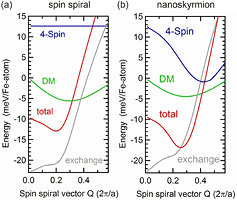
Figure 17. The system of one monolayer Fe on Ir(1 1 1). Comparison of the density functional theory derived energetics of a (a) single Q-state, i.e. a spin spiral, and (b) the nanoskyrmion lattice (all taken from [15]).
Download figure:
Standard image High-resolution imageThe nanoskyrmion lattice is very stable and we observe no change upon application of an external field of up to B = 9 T, see figures 18(a) and (b), as expected from the energy dispersion of the total energy with a rather deep minimum, figure 17(b). However, when applying voltage pulses between tip and sample the rotation of magnetic domains can be observed. While this can be measured, of course, with a magnetic tip, here we chose to display STM measurements with a non-magnetic tip to demonstrate how the tunneling anisotropic magnetoresistance (TAMR) effect can be exploited to obtain information about the magnetic state of the sample (see section 4). Figure 18(c) shows a simulated STM image where atoms with magnetization components along ![$\left[11\bar{2}\right]$](https://content.cld.iop.org/journals/0953-8984/26/39/394002/revision1/cm497111ieqn048.gif) have a larger apparent height compared to atoms with a magnetization perpendicular to that axis due to TAMR [15, 27]. The lines running along directions enclosing 120° in the STM image of figure 18(d) thus show that in this image area all three rotational domains are present. A voltage pulse between tip and sample now leads to a change of the domain structure, in this case only one of the three rotational domains remains when the area is imaged again, see figure 18(e). This shows that even a significant perturbation of the system does not alter this robust two-dimensional magnetic ground state, but only leads to a change of the rotational domain structure.
have a larger apparent height compared to atoms with a magnetization perpendicular to that axis due to TAMR [15, 27]. The lines running along directions enclosing 120° in the STM image of figure 18(d) thus show that in this image area all three rotational domains are present. A voltage pulse between tip and sample now leads to a change of the domain structure, in this case only one of the three rotational domains remains when the area is imaged again, see figure 18(e). This shows that even a significant perturbation of the system does not alter this robust two-dimensional magnetic ground state, but only leads to a change of the rotational domain structure.

Figure 18. Stability of the nanoskyrmion lattice. (a), (b) SP-STM constant-current images showing that the magnetic state is unchanged in external magnetic fields up to 9 T. (c) Simulation of an STM image with TAMR, atoms with magnetization components along ![$\left[11\bar{2}\right]$](https://content.cld.iop.org/journals/0953-8984/26/39/394002/revision1/cm497111ieqn049.gif) appear brighter. (d) TAMR-STM constant-current measurement of all possible rotational magnetic domains imaged with a non-magnetic tip (U = + 5 mV, I = 1 nA, T = 13 K). (e) Same as (d) after a voltage pulse; only one of the rotational domains is present.
appear brighter. (d) TAMR-STM constant-current measurement of all possible rotational magnetic domains imaged with a non-magnetic tip (U = + 5 mV, I = 1 nA, T = 13 K). (e) Same as (d) after a voltage pulse; only one of the rotational domains is present.
Download figure:
Standard image High-resolution image7. 2. Skyrmions in the PdFe bilayer on Ir(1 1 1)
The skyrmion lattice found in a PdFe bilayer on Ir(1 1 1) only exists in an external magnetic field and is the first interface-driven skyrmion lattice in the class of magnetic field induced skyrmion lattices [4]. Previous studies reported skyrmion lattices in B20 materials such as MnSi [51], FeCoSi [52], FeGe [54], or Cu2OSeO3 [55], which have a chiral crystal structure. The physics of all these systems is similar, but they are distinct from the four-spin interaction induced nanoskyrmion lattice in the Fe monolayer on Ir(1 1 1). The PdFe bilayer exhibits a spin spiral ground state, see figure 19(a). In an external magnetic field transitions to other magnetic phases can be observed: at intermediate fields a hexagonal skyrmion lattice is induced (b) which saturates to a ferromagnetic state at even higher magnetic fields (c). This field-dependent behavior, see sketches in (d), is typical for these field-induced skyrmion lattices.
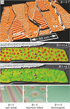
Figure 19. SP-STM measurements of the PdFe bilayer on Ir(1 1 1) in dependence on an external magnetic field at T = 8 K. (a) B = 0 T: spin spiral state, (b) B = 1.4 T: hexagonal skyrmion lattice, (c) B = 2 T: ferromagnetic phase. (d) Sketch of the different magnetic phases (all taken from [4]).
Download figure:
Standard image High-resolution imageObviously, the deposition of Pd onto the nanoskyrmion lattice of the Fe-ML on Ir(1 1 1) leads to a significant change of the magnetic ground state: The PdFe bilayer exhibits a spin spiral ground state with an approximately seven times larger period than the two-dimensional ground state of the uncovered Fe/Ir(1 1 1), see figure 20(a) for comparison, where the gray-scale has been adjusted separately to simultaneously see the spin spiral of PdFe and the nanoskyrmion lattice of the Fe ML in one image. Figure 20(b) shows a sample at intermediate magnetic field, where areas of spin spiral and skyrmion lattice coexist. This measurement has been performed with a tip which is magnetized mostly in-plane; the arrow indicates the tip magnetization, which was derived from the analysis of the magnetic contrast. As in SP-STM the magnetic contrast reflects the projection of tip and sample magnetization this leads to a bright-to-dark gradient of a skyrmion along the tip magnetization axis. From this image it is apparent, that all skyrmions have the same rotational sense not only within one island, but also in independent islands, as is expected from the directionality imposed by the DM interaction. The spin spiral is now inhomogeneous due to the applied magnetic field, but also here one can see the unique rotational sense which is identical to that of the skyrmions. When the lines of the spin spiral run parallel to the tip magnetization axis the magnetic contrast vanishes (see left end of top island).
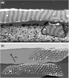
Figure 20. SP-STM measurements of the PdFe bilayer on Ir(1 1 1) at T = 8 K. (a) B = 0 T: the spin spiral state in the PdFe wire and island is visible together with the nanoskyrmion lattice in the Fe ML on Ir(1 1 1) [15], (b) B = − 1 T: coexistence of spin spiral and skyrmions with unique rotational sense, the tip magnetization direction is indicated by the arrow (for both: gray-scale of the layers adjusted separately for better visibility of the magnetic state).
Download figure:
Standard image High-resolution image7. 3. Writing and deleting single magnetic skyrmions
While in previous studies the samples were in the thermodynamic ground state, for PdFe the ratio between the energy barrier separating two topologically distinct states and the measurement temperature is much larger. This can be exploited to study ground state properties at slightly higher temperature, i.e. about T > 8 K, or to trap the magnetic configuration in a metastable state for lower temperatures. This can be understood e.g. for the transition between skyrmions (S = 1) and the ferromagnetic state (S = 0) within a simple two state model, see sketch in figure 21(a): when the magnetic field is increased, the energy of the skyrmion state rises and the ferromagnetic state becomes the lower energy state. When the system is in the ferromagnetic state and the magnetic field is lowered at reduced temperature, then the energy barrier cannot be overcome and the ferromagnetic state is preserved to smaller magnetic field values, even though the topologically protected skyrmion has a lower energy, see top sketch in figure 21(a). It has been found, that the energy barrier between the two states can be overcome not only by thermal excitation, but also the tunnel electrons can induce a transition between the topologically distinct states. Note that the potential landscape is asymmetric, as the two states are not linked by a symmetry operation, and different attempt frequencies and lifetimes of the two states are likely.
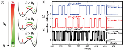
Figure 21. Switching between different magnetic states. (a) Sketch of the energy barrier between a skyrmion (S = 1) and the ferromagnetic state (S = 0) as the magnetic field B is varied; B0 is the field at which both states are degenerate in energy. (b)–(d) Time-traces of the spin-polarized normalized dI/dU signal as the system switches between the presence (1) and the absence (0) of a skyrmion in the PdFe bilayer on Ir(1 1 1) at T = 4 K. Note that the power of the tunnel current is 35 nW for all three measurements. Parameters as indicated.
Download figure:
Standard image High-resolution imageThe telegraph noise in figures 21(b)–(d) demonstrates the switching between the presence of a skyrmion (S = 1) and its absence (S = 0) for different parameters at the same sample position. While the power of the injected tunnel current is identical for all three traces, the response of the system is very different: for (b) the switching takes place at a time scale of several seconds and the histogram to the right shows that the skyrmion state is slightly favored. In (c) the magnetic field is increased, which leads to a shift of the population of the states towards the ferromagnetic state, as expected. However, a measurement at the same magnetic field as in (c) but at larger bias voltage leads to a significant increase of the switching frequency between the two states (d). This cannot be explained by local Joule heating of the sample, as the power of the tunnel current is identical, but is solely due to the higher energy of the injected electrons. In addition, the probability to observe a skyrmion has significantly increased, which must be due to spin-transfer torque resulting from the spin-polarized tunnel current between tip and sample.
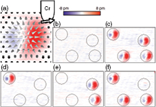
The control over the state in the parameter space of temperature, magnetic field, and tunnel current values allows a proof of principle that data storage using topological charges is feasible, as demonstrated in figure 22. The color scale shows the difference between topography images and the red-blue contrast indicates the presence of a skyrmion, see figure 22(a). A sample area with four skyrmions is chosen and it is demonstrated that various topological configurations can be realized by writing and deleting skyrmions at the four characteristic spots.
Figure 22. SP-STM measurements of a group of isolated skyrmions in the PdFe bilayer on Ir(1 1 1) at T = 4 K, B = 3.25 T. (a) The difference images show a blue-red contrast at the position of a skyrmion, the cones represent the magnetization direction of the sample, the tip magnetization is sketched. (b)–(f) Show how the skyrmions can be deleted and written independently and arbitrary configurations of topological charges can be imprinted (all panels taken from [4]).
Download figure:
Standard image High-resolution image
8. Summary
Spin-polarized scanning tunneling microscopy in combination with an external magnetic field has proven to be a powerful technique to reveal complex spin textures down to the atomic scale. The discovery of interface-induced chiral domain walls and spin spirals with unique rotational sense in ultra-thin transition metal films was the first step in this novel research direction, that now deals with the interaction of such systems with lateral spin-polarized currents for spintronics applications. The discovery of interface-driven skyrmion states in atomically thin films and bilayers has demonstrated that in principle state-of-the-art multilayer fabrication techniques could be used for the realization of skyrmion-based devices. Moreover a big step towards applications has been the realization of the writing and deletion of single magnetic skyrmions with vertical spin-polarized tunnel currents. In such a geometry the spin-transfer torque of the impinging electrons can be exploited to give the switching a directionality, demonstrating the great potential for future spintronics devices.
Acknowledgments
We would like to thank J E Bickel, G Bihlmayer, S Blügel, M Bode, J Brede, P Ferriani, C Hanneken, M Heide, S Heinze, S Meckler, M Menzel, N Mikuszeit, Y Mokrousov, S Ouazi, N Romming, S Schröder, D Serrate, E Y Vedmedenko, R Wieser, B Wolter and Y Yoshida for their contributions. Financial support from the ERC Advanced Grant FURORE and by the Deutsche Forschungsgemeinschaft via the SFB 668 is gratefully acknowledged.