
Abstract
Recently developed manufacturing technologies use high pressure and various doping additions to prepare bulk MgB2-based materials with a high critical current density measured by the magnetization method. We use a contactless transformer method, which is based on studying the superconductor response to an induced transport current, to measure AC losses in bulk MgB2 rings synthesized under high pressure. The obtained dependence of the losses on the primary current (applied magnetic field) is fitted by a power law with an exponent of ∼2.1 instead of the cubic dependence predicted by Bean's model and power law electric field–current density (E–J) characteristics with a large exponent. An unusually strong dependence of the AC losses on the frequency is also observed. It is shown that the E–J characteristic of bulk MgB2 is well fitted by the dependence used in the extended critical state model based on account of the viscous vortex motion in the flux flow regime. Numerical simulation using this E–J characteristic gives current and frequency AC loss dependences that agree well with the experimental results.
Export citation and abstract BibTeX RIS
1. Introduction
It is expected that bulk MgB2-based materials will be able to successfully compete with high-temperature bulk superconductors in fault current limiters, electrical motors, generators, superconducting magnets, passive levitated bearings and shields for AC and DC magnetic fields [1–8]. Recently developed manufacturing technologies use high pressure and various doping additions to prepare bulk MgB2 materials with a high critical current density Jc. Evaluations of Jc using the results of magnetization measurements and the critical state model give values of 106 A cm−2 at 20 K in a magnetic field of up to 1 T [3, 9–11].
The problem of AC loss evaluation is an important issue for the development of superconducting devices for applications under AC conditions. The AC losses determine the ranges of the rated currents and magnetic fields for the devices, the required power of the cryogenic equipment and the economic efficiency. Other aspects of AC losses are connected with studying the physical properties of superconductors, such as the microscopic motion of the Abrikosov vortices and the phase state of the vortex lattice. A number of papers have been devoted to the study of AC losses in MgB2 tapes and wires [12, 13]. The electric (four-point), magnetic and calorimetric methods are widely used for the measurement of AC losses. The advantages and drawbacks of these methods are discussed, for example, in [13] respect to superconducting tapes.
In this paper we report the results of measuring AC losses in MgB2 bulk rings synthesized under high pressure. In contrast to the four-point, magnetization and calorimetric methods, we apply a contactless transformer method which allows us to study the characteristics of a superconductor with an induced transport current.
Our experimental method is described in detail in section 2. Description of the experimental setup and tested samples is given in section 3. In section 4 we report the experimental results. The obtained dependence of the losses on the primary current is fitted by a power law with an exponent of ∼2.1 instead of the cubic dependence predicted by Bean's model. An unusually strong dependence of the AC losses on the frequency is also presented. In section 5 we discuss the obtained results and show that the observed AC loss behavior is expected for samples with the E–J characteristics (E—electric field, J—current density) described by the extended critical state model based on taking the viscous vortex motion in the flux flow regime into account.
2. Experimental method
Measurements of AC losses in bulk superconducting samples with a transport current are usually based on the four-point method which requires a high current supply of up to tens or even hundreds of thousands of amperes and high quality contacts. One contactless method suitable for samples in the form of a closed loop (hollow cylinder, ring or short-circuited coil) is based on using the transformer configuration (figure 1(a)) [14, 15]. A superconducting closed loop forms the secondary coil of a transformer in which the primary coil is connected with an AC source. To increase the coupling between the coils, they are centered on a ferromagnetic core in the form of a laminated rod (open core design). The procedure for AC loss determination in samples with induced current relies on measuring, with the help of the Hall-probe technique (figure 1(a)), the magnetic flux density as a function of the instantaneous current in the primary coil. This method has been previously used by the authors of the present work to measure AC losses in BSCCO cylinders [14, 15]. The main advantages of this method are that (i) high currents of up to several tens of thousands of amperes can be achieved in a superconductor using conventional laboratory equipment, (ii) no current terminals or measuring contacts to a superconductor are required and (iii) the measurement results are not influenced by heating due to losses in the contacts.

Figure 1. The setup for measurement of AC losses by a contactless transformer method (a) and the tested MgB2 ring (b).
Download figure:
Standard imageTo clarify the basics of the method, let us use the well-known equations of an ideal two-coil transformer,


where u1 is the voltage drop across the primary coil, usc is the voltage appearing across the superconductor's secondary short closed coil, i1 and isc are the currents in the primary and secondary coils, and L1 and L2 are their inductances, M is the mutual inductance of the coils and R is the resistance of the primary coil.
The Hall probe located on the top of the rod gives the total magnetic field BΣ = B1 + B2, where B1 and B2 are the magnetic fields produced by the primary and secondary currents, respectively. These fields have opposite directions and are proportional to the currents in the coils, B1 = kb1i1N and B2 = kb2isc (N is the number of turns in the primary coil, kb1 and kb2 are the proportionality coefficients). Therefore, BΣ = kb1i1N + kb2isc and the current in the superconductor is

The voltage drop in the ring is determined from (2) with substitution of (3),

The expression for AC loss power can be obtained by multiplying (3) by (4) and integrating over the current period T. If kb1 and kb2 are independent of the currents, we have

This expression shows that the AC loss values are proportional to the area of the hysteresis loop on the BΣ–i1 plane.
The right-hand side of (5) contains only the directly measured quantities BΣ and i1. In contrast to difference methods, the measurement accuracy does not depend on the value of the losses in the primary coil. Errors in the determination of M and kb2 affect only the magnitude of the losses but not the dependence of the losses on the current and frequency.
3. Experimental samples and setup
3.1. Experimental samples
The samples were synthesized under quasihydrostatic high pressure conditions, 2 GPa, 1050 °C for 1 h, from a mixture of Mg and B powders with 4.0 μm average grain size taken in MgB2 stoichiometry with the addition of 10% SiC. The initial amorphous boron contained 0.94% C, 0.35% N and 0.72% H (ring 1) or 0.34% N, 0.47% C, 0.37% H and 1.5% O (ring 2). The boron was mixed and milled with Mg chips in a high speed planetary activator and then 200–800 nm SiC granules were added. The technology was described in detail in [16]. Rings with an outer diameter of 24.3 mm, heights of 7 mm (ring 1, figure 1(b)) and 7.7 mm (ring 2) and a wall thickness of 3.2 mm were cut out of high pressure synthesized blocks. From the magnetization experiments, the critical temperature of the MgB2 samples was estimated to be 39 K.
3.2. Experimental setup
The experimental setup included a two-coil transformer where a MgB2 ring forming a single-turn secondary coil was placed inside a copper 700-turn primary coil, as shown in figure 1(a). The primary normal metal coil with an internal diameter of 25 mm and a height of 32 mm was wound from 0.18 mm diameter copper wire. The ferromagnetic laminated open core assembled from 0.3 mm transformer steel sheets had an effective diameter of 15 mm and a height of 48 mm and was inserted into the ring.
The whole device was placed in a cryostat with liquid helium at 4.2 K. The primary coil was connected in series to a circuit including a generator of AC voltage, two variable resistors and a resistive shunt of 0.335 Ω for the current measurement. A Hall probe with a sensitivity of 100 mV T−1 at 4.2 K was placed at the center of the top of the ferromagnetic rod, as shown in figure 1(a). The voltage generated by the Hall probe was amplified by a factor of 100 and acquired along with the trace of the primary current and voltage drop across the primary coil by a multichannel data acquisition device. The recording rate was 500 000 samples s−1 per channel. To prevent heating of the ring due to AC losses, a special electronic switch short-circuited one of the resistors for several AC periods, thus providing high currents only for ∼0.1 s. The pause between measurements was about 15 min to provide cooling of the ring to the bath temperature.
3.3. Determination of the transformer device parameters
In order to determine the parameters given in equations (1)–(5), preliminary measurements were performed. From a DC experiment, the resistance of the primary coil at 300 K (room temperature) was found to be 66 Ω and it dropped to 0.35 Ω at 4.2 K.
The main parameters of a transformer are experimentally determined from open and short circuit tests. The inductance, L1 = 0.025 H, was obtained from an AC measurement without a ring (the open circuit test). The same inductance was obtained with a ring at 77 K, which indicated that the superconductor resistance in the normal state was much larger than the transformer impedance.
The proportionality coefficient kb1 was also obtained in the open circuit test, without a secondary coil, when the primary coil was connected with a DC source. Our experiments demonstrated that the inductance and kb1 do not depend on the magnitude of the primary current, in complete agreement with the well-known linearity of open core magnetic systems [17, 18].
To determine kb2, we calculated the magnetic field distribution in the device with the help of COMSOL (COMSOL Multiphysics is a commercial FEM software package) using a 2D axially symmetric model in which the rod was replaced by a ferromagnetic lossless cylinder with relative magnetic permeability ranging from 100 to 10 000. The superconducting ring was simulated by a single-turn coil of the same height and external diameter. To simulate various penetration depths of the magnetic field into the superconductor the coil thickness was varied from 0.5 to 3.2 mm. The simulation with the use of the COMSOL program showed that kb1 = kb2 within an accuracy of 1%. This is explained by the choice of the point for the field measurement at the center of the rod top where the field depends only on the ampere-turns and not on the dimensions of the coil producing the field. Therefore, BΣ = kb (i1N + isc), where kb is the general notation for kb1 and kb2.
The mutual inductance M can be found from the short circuit test at low primary currents when the AC losses can be neglected. Actually, the voltage drop across a type-II superconductor under AC conditions is determined by the electric field E induced by the magnetic field H penetrating into the superconductor. From the Faraday equation  in the 1D case, the maximum electric field is estimated as

where H0 is the magnetic field intensity amplitude, μ0 is the vacuum magnetic permeability and ω = 2πf, where f is the magnetic field frequency. The magnetic field penetration depth δ can be estimated using the Bean model δ = H0/Jc (Jc is the critical current density). Therefore, the maximum of the electric field and the voltage drop usc decrease proportional to the square of the amplitude of the applied magnetic field or current, and at a low primary current, usc in equation (2) can be neglected. Under short circuit tests the voltage drop across the primary coil is determined, on the one hand, by equation (1) and, on the other hand, can be expressed as

From equations (1), (2) and (7) at us = 0,

where Ls = 0.0067 H is the inductance of the primary coil measured at low current (less than 0.2 A) and at a temperature of 4.2 K when the losses in the superconducting ring are negligible (the short circuit test).
At a low primary current the superconducting current is proportional to the primary current. The Hall probe registers a finite magnetic field proportional to the primary current. This effect is explained by the finite sizes of the primary coil, ring and magnetic core, and, hence, imperfect magnetic coupling between the coil and the ring. From equations (2) and (3) we obtain

where  is the proportionality coefficient between BΣ and Ni1 measured at a low primary current. Equations (8) and (9) determine the mutual inductance M.
3.4. The influence of a ferromagnetic core
All the expressions above were obtained assuming that the transformer is ideal. In reality, a transformer with a ferromagnetic core has hysteresis and eddy-current losses. The losses determined by equation (5) also include the losses in the core. We used a laminated core in the form of a rod made of thin, insulated soft iron sheets (open core design) providing high linearity of the B–H characteristics of the magnetic system and low hysteresis losses.
Let us consider the contribution of eddy-current losses. As shown in [18], the losses in a thin sheet are mostly due to the normal component of the magnetic field (i.e. the radial component of the magnetic field in our device). The radial component at the lateral surface of the ferromagnetic rod was calculated using COMSOL. A ring in the superconducting state was simulated by a single-turn coil with a resistivity of 10−12 Ω m. Figure 2 shows the distribution of the magnetic flux density Br at the lateral surface of the core versus the z-coordinate directed along the device axis, calculated for a current of 1 A in a 700-turn primary coil. The maximum of the radial field Br in the device without a ring is about 0.035 T while, in the device with a ring, it does not exceed 0.003 T. The obtained field distribution is practically independent of the primary current frequency.

Figure 2. The calculated radial component of the magnetic field density at the lateral surface of the ferromagnetic rod without (red dotted line) a ring and with a normal conducting ring with a resistivity of 10−12 Ω m as a secondary (black solid line) at a primary current of 1 A. The inset shows the directions of the axes. Due to symmetry we only show the field distribution in half of the rod (z > 0).
Download figure:
Standard imageOur estimation of the loss power in a single sheet of 0.3 mm in thickness was performed on the basis of the expressions given in [19] and gave a value of about 10−3 W for the maximum Br = 0.035 T (corresponding to a 1 A current in the primary coil) at a frequency of 120 Hz. The rod consists of 50 isolated sheets but the centrally located sheets have smaller losses—the radial component decreases towards the center. Averaging and summing over all the sheets, we estimate the maximum total loss power in the rod as 0.05 W at a current of 1 A (rms value). Taking into account that the losses are proportional to  , we evaluate the loss power in the core of the device with the ring in the superconducting state (Br = 0.003 T and a frequency of 120 Hz) as 5 × 10⁻⁴ W. The losses change as the square of the frequency. As we shall see below, this value is negligible in comparison to the AC losses in the superconductor. For example, at a primary current of 4 Arms and frequency of 120 Hz, the losses in the superconductor are 0.17 J per cycle (see figure 4), or 20.4 W, while the core losses in the same conditions are 8 × 10⁻³ W.
4. Measurement results
Typical oscilloscope traces of the primary current and magnetic field density are presented in figure 3(a). The AC loss measurements were performed until quenching (transition of the ring into the non-superconducting state), characterized by the appearance of distortions in the voltage waveform. A typical BΣ–i1 loop is shown in figure 3(b). At a low current (<0.2 A, rms value) the loop degenerates into a straight line, thus showing that the AC losses in the superconductor and magnetic core are less than the precision of the measurements.
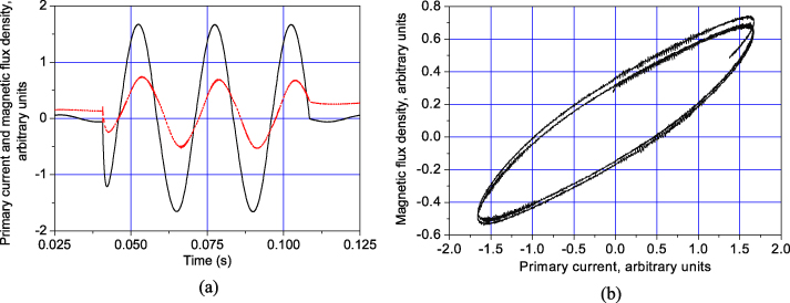
Figure 3. (a) Typical waveforms of the current (black solid curve) and magnetic flux density (red dotted curve); (b) the loop BΣ–i1. The frequency of the current is 40 Hz.
Download figure:
Standard imageThe current and frequency dependences of the AC losses per cycle determined using the obtained waveforms of i1 and BΣ and equation (5) are shown in figures 4–6 for ring 2. The losses in ring 1 are about 10% lower and have the same dependences on the current and frequency.

Figure 4. The dependence of the AC losses in the MgB2 ring on the primary current at different frequencies and a temperature of 4.2 K for ring 2.
Download figure:
Standard image
Figure 5. Losses per cycle as a function of frequency at different rms currents in the primary coil and at a temperature of 4.2 K for ring 2.
Download figure:
Standard image
Figure 6. The logarithm of the AC losses in the MgB2 ring and the BSCCO cylinder as a function of the logarithm of the primary current. Here Pnorm = 1 J and Inorm = 1 A (rms value).
Download figure:
Standard image5. Discussion
The measurement results show that the AC losses in the MgB2 rings have the following features: (i) the loss value per cycle depends strongly on the frequency (∼1/f0.4 at an rms current of 5 A), (ii) the dependences of the losses on the primary current are well fitted by a power law P ∼ im with an exponent m of about 2.1 (figure 6).
The Bean model predicts AC losses independent of frequency and fitted by a power law with an exponent of about 3 [14, 20]. The widely used model based on the power law E–J characteristics, E ∼ Jn, gives deviations from the Bean model results, but, even at a relatively low index of n ≈ 7, these deviations are not very pronounced. For comparison, we measured AC losses in a BSCCO cylinder using the same experimental technique and Hall sensor (the experimental details are given in the appendix).
The dependence of the AC losses in BSCCO on the primary current is fitted by a power law with an exponent m of about 2.8 (figure 6, curves for BSCCO). These results are in full accordance with the theoretical and experimental investigations presented in [14, 15, 21–23].
In order to obtain an adequate description of the E–J characteristics of the investigated samples, we compared AC losses based on different models with Bean's model, which gives an exact analytical solution [14], calculating AC losses using COMSOL within the axial-symmetric 1D approximation where the primary coil, superconductor and core are infinitely long. Using the power law E–J characteristics with large indices n (n > 15), we obtain good accordance of the results with Bean's model. The simulation of the BSCCO cylinder with n = 7 gives an m of about 2.8. An attempt to use the power law E–J characteristics with lower indices n (n < 5) to simulate the AC loss behavior in the MgB2 ring leads to m ≈ 2.5, which is sufficiently higher than the value of 2.1 found experimentally for the MgB2 rings. This discrepancy needs an explanation.
To clarify the reasons for this behavior of the AC losses in MgB2, we measured the E–J characteristics of the samples applying pulses of direct current to the primary coil. In our experimental setup (figure 1(b)), the AC source was replaced by a DC one. At low primary currents, when the currents induced in the ring are less than the critical value, the measured magnetic field BΣ is proportional to the primary current. The waveforms of the primary current and magnetic field are given in figure 7(a) for a case where the maximum current in the ring exceeds the critical current value slightly. The magnetic field increases linearly with the primary current until the ring current achieves the critical value (figure 7(b)). After this point the dependence becomes strongly non-linear—the magnetic field penetrates into the ring.
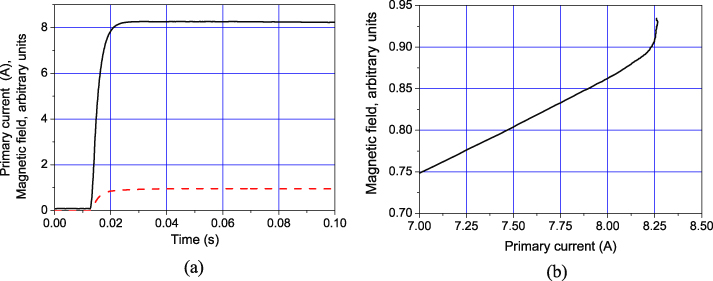
Figure 7. The current in the primary coil (black solid line) and the magnetic field (red dashed line) in the DC pulse experiment (a); magnetic field versus primary current (b).
Download figure:
Standard imageThe current in the ring and the voltage drop across it were determined using equations (3) and (4). The voltage–current characteristics of ring 2 obtained in this experiment are shown in figure 8 and demonstrate almost linear increase after the critical value. For comparison, the calculated power law E–J dependence with the index n = 100 and the same critical current determined by the criterion 1 μV cm−1 is also presented on the plot (blue dotted line). Assuming that the superconductor is homogeneous and the current density is uniform over the superconductor cross-section, we obtain that the E–J characteristics are well described in the framework of the extended critical state model [24],

where ρf estimated from the curve of figure 8 equals about 1.8 × 10⁻⁹ Ω m, the critical current density Jc ≅ 22 000 A cm−2 and the critical current Ic ≅ 5500 A for ring 2. For ring 1 these values are ρf = 10−9 Ω m; Jc ≅ 21 000 A cm−2 and Ic ≅ 4500 A.
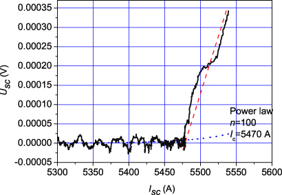
Figure 8. The voltage–current characteristics of a MgB2 ring.
Download figure:
Standard imageExpression (10) fits well the E–J characteristics of low-temperature and some high-temperature superconductors [24–27] in which the creep flux can be neglected. The E–J characteristics are determined by the flux flow regime and, in the general case, the flux flow resistivity ρf is a function of the local magnetic field and temperature [25, 26]. Note that in the Bean model ρf is assumed to be infinitely large.
The calculation results for MgB2 with E–J characteristics in the form of (10) are shown in figure 9. For the considered approximation of an infinitely long primary coil, superconducting cylinder and core, the magnetic field at the superconductor surface equals the primary current multiplied by the number of turns per length unit.

Figure 9. Calculation using the extended critical state model in the axial-symmetric 1D approximation at ρf = 10−9 Ω m: (a) logarithm–logarithm loss dependence at f = 100 Hz, the losses are normalized by their value Pnorm at Hnorm = 1.2 × 10⁵ A m−1; (b) the frequency dependence at H0 = 1.2 × 10⁵ A m−1, the losses are normalized by their value at f = 80 Hz.
Download figure:
Standard imageIn contrast to Bean's model, the extended model based on (10) is characterized by an increase of the current density above the critical value. The relative increase of the current density ΔJ/Jc due to a finite flux flow resistivity can be evaluated using (6) as

where dsc is the characteristic size of a superconductor—its radius or thickness.
For the evaluation of AC losses in low-temperature superconductors, one can neglect ΔJ in a wide range of frequencies and applied magnetic fields (the diameter of a superconducting filament is less than 10 μm or even 1 μm; the critical current density is of the order of 1010 A m−2). Therefore, low-temperature superconductors are well described by Bean's model.
The thickness of the investigated MgB2 samples is three orders of magnitude higher. Therefore, when ωH0 is relatively low, the penetration depth δ ≈ H0/Jc and the current density is close to the critical value. In this case the losses can be evaluated using Bean's model: the losses per period are proportional to  . With increase of the applied magnetic field or/and frequency, the current density increases and can exceed the critical value by several times. In this case the loss density is p = EJ = ρf(J − Jc)J ≈ ρfJ2 and the properties of a superconductor are close to the properties of a normal metal where the losses per period are proportional to
  . In a normal metal with the thickness larger than the skin depth, the losses per period are proportional to
  .
.
The AC loss calculation was performed numerically using the AC/DC magnetic field module of the COMSOL Multiphysics program and the relation (10) between the electric field and the current density (extended critical state model). The calculation results given in figure 9 agree well with the analysis above: the fitting exponent for AC losses decreases from about 2.9 at low field to 2.2 at high field and the frequency dependence is proportional to 1/f0.38. These results are also in full accordance with our experiment. Note that our results agree qualitatively with the field dependence of AC losses in a bulk MgB2 sample reported in [27]. The authors of the cited paper observed a gradual decrease of the exponent m from 3 to 1 with increase of the magnetic field. The dependence of the AC losses on the field contains a long segment with m = 2.
6. Conclusion
The application of the transformer technique allowed us to measure the AC losses and E–J characteristics of bulk MgB2 samples with an induced transport current. The dependence of the AC losses on the current is well fitted by a power law with an exponent of about 2.1. The transport losses per cycle scale with the frequency as 1/f0.4. The measured E–J characteristics are well described by the extended critical state model, which gives the loss dependences on the magnetic field and frequency close to the experimental results.
Appendix:
The BSCCO cylinders were fabricated using the melt cast technology developed by Hoechst [28, 29]. The melt cast process relies on casting a homogeneous melt of the starting materials in molds of the required shape and size. The hot melt is cast into rotating molds, where it is evenly distributed on the inner sides of the walls. After solidification of the melt, the elements undergo a suitable heat treatment in order to obtain proper superconducting properties. The obtained casts were machined into 30 mm height, 35 mm inner diameter and 5.1 mm wall thickness cylinders. Characterization of the specimens by the DC four-point method gave a value of 570 A cm−2 for the critical current density from the 1 μV cm−1 criterion and a critical temperature of 94 K. The DC current–voltage characteristics and critical current versus magnetic field have been studied in detail and described elsewhere [29]. Using the transformer experimental configuration we studied the response of the cylinders to a step of the current in the primary coil [15]. For current densities above about 600 A cm−2 the E–J characteristics are well fitted by a power law with the power index equal to 7.
The BSCCO cylinder forms a single-turn secondary coil. It was placed inside the copper 400-turn primary coil of a two-coil transformer. A primary coil with an internal diameter of 38 mm and a height of 38 mm was wound from 0.3 mm diameter copper wire. A ferromagnetic laminated rod assembled from transformer steel of 0.3 mm thickness with an effective diameter of 20 mm and height of 48 mm was inserted into the cylinder.